LG W246BH Le manuel du propriétaire
- Catégorie
- Climatiseurs split-system
- Taper
- Le manuel du propriétaire

ROOM AIR CONDITIONER
OWNER'S MANUAL
Please read the operating instructions and safety precautions carefully
and thoroughly before installing and operating your room air conditioner.
MODELS(MODÉLES) : WG/C/N CHASSIS
CLIMATISEUR DE PIÈCE
MANUEL DU PROPRIÉTAIRE
Veuillez lire soigneusement et au complet les instructions de
fonctionnement et les mesures de sécurité avant d’installer et d’utiliser
votre climatiseur de pièce.
ENGLISH FRANÇAIS

2 Room Air Conditioner
Window-Type Air Conditioner Owner’s Manual
TABLE OF CONTENTS
FOR YOUR RECORDS
Write the model and serial numbers here:
Model #
Serial #
You can find them on a label on the side of each unit.
Dealer's Name
Date Purchased
■ Staple your receipt to this page in the event you need it
to prove date of purchase or for warranty issues.
READ THIS MANUAL
Inside you will find many helpful hints on how to use and
maintain your air conditioner properly. Just a little preventive
care on your part can save you a great deal of time and
money over the life of your air conditioner.
You'll find many answers to common problems in the chart
of troubleshooting tips. If you review our chart of
Troubleshooting Tips first, you may not need to call for
service at all.
PRECAUTION
• Contact the authorized service technician for repair
or maintenance of this unit.
• Contact the installer for installation of this unit.
• The air conditioner is not intended for use by young
children or invalids without supervision.
• Young children should be supervised to ensure that
they do not play with the air conditioner.
• When the power cord is to be replaced, replacement
work shall be performed by authorized personnel only
using only genuine replacement parts.
• Installation work must be performed in accordance
with the National Electric Code by qualified and
authorized personnel only.
Safety Precautions..........................3
Before Opeation ..............................7
Introduction ....................................8
Installation ......................................9
Operating Instructions .................14
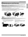
Maintenance and Service ............21

Owner’s Manual 3
ENGLISH
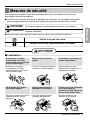
Safety Precautions
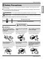
Safety Precautions
To prevent injury to the user or other people and property damage, the following instructions
must be followed.
■ Incorrect operation due to ignoring instruction will cause harm or damage. The seriousness
is classified by the following indications.
■ Meanings of symbols used in this manual are as shown below.
WARNING
CAUTION
This symbol indicates the possibility of death or serious injury.
This symbol indicates the possibility of injury or damage to properties only.
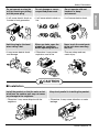
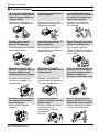
WARNING
■ Installation
Be sure not to do.
Be sure to follow the instruction.
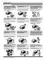
Don’t use a power cord, a
plug or a loose socket which
is damaged.
• Otherwise, it may cause a
fire or electrical shock.
Always plug into a grounded
outlet.
• Otherwise, it may cause a
fire or electrical shock.
Do not modify or extend the
power cord length.
• It will cause electric shock or
fire due to heat generation.
Do not disassemble or
modify products.
• It may cause failure and
electric shock.
Be caution when unpacking
and installing.
• Sharp edges may cause
injury.
Do not use the power cord near
flammable gas or combustibles
such as gasoline, benzene,
thinner, etc.
• It may cause explosion or
fire.
Gasolin

4 Room Air Conditioner
Safety Precautions
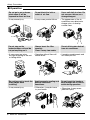
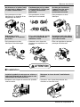
■ Operation
Do not place the power cord
near a heater.
• It may cause fire and electric
shock.
Do not allow water to run
into electric parts.
• It will cause failure of machine
or electric shock.
Use a soft cloth to clean. Do
not use wax, thinner, or a
strong detergent.
• The appearance of the air
conditioner may deteriorate,
change color, or develop
surface flaws.
Wax
Thinner
Ventilate the room well when
using this appliance
together with a stove, etc.
• An oxygen shortage may
occur.
Turn off the power and
breaker firstly when
cleansing the unit.
• Since the fan rotates at high
speed during operation, it may
cause injury.
Turn off the main power
switch when not using it for
a long time.
• Prevent accidental startup and
the possibility of injury.
Unplug the unit if strange
sounds, odors, or smoke
come from it.
• Otherwise it may cause fire
and electric shock accident.
Do not open the suction
inlet grill of the product
during operation.
• Otherwise, it may electrical
shock and failure.
If water enters the product, turn
off the the power switch of the
main body of appliance. Contact
service center after taking the
power-plug out from the socket.
Do not place heavy object
on the power cord and take
care so that the cord should
not be pressed.
• There is danger of fire or
electric shock.
Do not share the outlet with
other appliances.
• It will cause electric shock or
fire due to heat generation.
Take the power plug out if
necessary, holding the head
of the plug and do not touch
it with wet hands.
• Otherwise, it may cause a
fire or electrical shock.

Owner’s Manual 5
ENGLISH
Safety Precautions
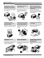
CAUTION
■ Installation
Do not operate or stop the
unit by inserting or pulling
out the power plug.
• It will cause electric shock or
fire due to heat generation.
Do not damage or use an
unspecified power cord.
• It will cause electric shock or
fire.
Do not operate with wet
hands or in damp
environment.
• It will cause electric shock.
Hold the plug by the head
when taking it out.
• It may cause electric shock
and damage.
When gas leaks, open the
window for ventilation
before operating the unit.
• Otherwise, it may cause
explosion, and a fire.
Never touch the metal parts
of the unit when removing
the filter.
• They are sharp and may
cause injury.
Install the product so that the noise or hot
wind from the outdoor unit may not cause
any damage to the neighbors.
• Otherwise, it may cause dispute with the
neighbors.
Keep level parallel in installing the product.
• Otherwise, it may cause vibration or water
leakage.

6 Room Air Conditioner
Safety Precautions
■ Operation
Be cautious not to touch the
sharp edges when
installing.
• It may cause injury.
Avoid excessive cooling and
perform ventilation
sometimes.
• Otherwise, it may do harm
to your health.
Do not insert the hands or
bars through the air inlet or
outlet during operation.
• Otherwise, it may cause
personal injury.
Do not put a pet or house
plant where it will be
exposed to direct air flow.
• It may cause injury.
Do not block the inlet or
outlet of air flow.
• It may cause product failure.
Use a soft cloth to clean. Do
not use wax, thinner, or a
strong detergent.
• The appearance of the air
conditioner may deteriorate,
change color, or develop
surface flaws.
Do not step on the
indoor/outdoor unit and do
not put anything on it.
• It may cause an injury
through dropping of the unit
or falling down.
Always insert the filter
securely.
Clean it every two weeks.
• Operation without filters will
cause failure.
Do not drink water drained
from air conditioner.
• It contains containments and
will make you sick.

Owner’s Manual 7
ENGLISH
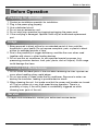
Before to Operation
Before Operation
1. Contact an installation specialist for installation.
2. Plug in the power plug properly.
3. Use a dedicated circuit.
4. Do not use an extension cord.
5. Do not start/stop operation by plugging/unplugging the power cord.
6. If the cord/plug is damaged, replace it with only an authorized replacement
part.
1. Being exposed to direct airflow for an extended period of time could be
hazardous to your health. Do not expose occupants, pets, or plants to direct
airflow for extended periods of time.
2. Due to the possibility of oxygen deficiency, ventilate the room when used
together with stoves or other heating devices.
3. Do not use this air conditioner for non-specified special purposes (e.g.
preserving precision devices, food, pets, plants, and art objects). Such usage
could damage the items.
1. Do not touch the metal parts of the unit when removing the filter. Injuries can
occur when handling sharp metal edges.
2. Do not use water to clean inside the air conditioner. Exposure to water can
destroy the insulation, leading to possible electric shock.
3. When cleaning the unit, first make sure that the power and breaker are turned
off. The fan rotates at a very high speed during operation. There is a
possibility of injury if the unit’s power is accidentally triggered on while
cleaning inner parts of the unit.
For repair and maintenance, contact your authorized service dealer.
Preparing for Operation
Usage
Cleaning and Maintenance
Service

8 Room Air Conditioner
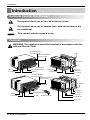
Introduction
This symbol alerts you to the risk of electric shock.
This symbol alerts you to hazards that could cause harm to the
air conditioner.
This symbol indicates special notes.
NOTICE
WARNING: This appliance should be installed in accordance with the
National Electric Code.
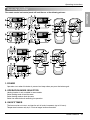
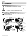
Vertical Air Deflector
(Horizontal Louver)
Horizontal Air Deflector
(Vertical Louver)
Air Discharge
Evaporator
Control Board
Evaporator
Control Board
Condenser
Base Pan
Brace
Brace
Cabinet
Front Grille Air Filter
Air Intake(Inlet Grille)
Vertical Air Deflector
(Horizontal Louver)
Horizontal Air Deflector
(Vertical Louver)
Air Discharge
Cabinet
Front Grille Air Filter
Remote Controller
Air Intake(Inlet Grille)
Compressor
Power Cord
Condenser
Base Pan
Compressor
Power Cord
Introduction
Symbols Used in this Manual
Features

Owner’s Manual 9
ENGLISH
Installation
Installation
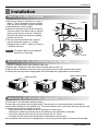
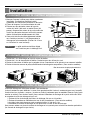
Select the Best Location
1. Measure the space for installation to assure a
good fit. The air conditioner must be installed
firmly into place to prevent vibration and noise.
2. Avoid exposure to direct sunlight.
3. Remove all obstacles from the rear of the unit.
There must be at least 50cm (20in.) of cleared
space around the rear of the unit. Obstacles
restricting the airflow may reduce the cooling
efficiency of the unit.
4. The unit should be installed with a slight tilt
towards the outside (approx. 3°) to allow
condensed water to drain. (About 10~15mm or
1/4 bubble with level)
The external grille must be exposed
outside for air discharge.
NOTICE
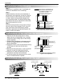
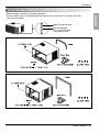
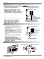
Remove the Air Conditioner From the Case
1. Remove 2 shipping screws from the back of the case.
2. Remove the 2 screws on each side of the case. Keep these for later use.
3. Slide out the air conditioner from the case by pulling the base-pan handle while bracing the case.
4. Remove the white Styrofoam shipping block from the compressor. (Applicable for some models)
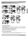
Attaching the Drain Pan (Optional)
The drain pan is used to collect condensed water.
The base-pan may overflow due to high humidity. The base-pan may also collect excess water when in
reverse mode (in Reverse Cycle models only). To drain the excess water, remove the drain cap from the back
of the unit and secure the drainpipe as follows:
1. Remove the drain pan located in the air discharge or on the barrier.
2. Remove the rubber cap from the hole on the base-pan. (Not applicable to all models)
3. Install the drain pan to the left corner of the cabinet with 2-4 screws.
4. Connect the drain hose to the hole located on the bottom of the drain pan.
You can purchase the drain hose or tubing locally to satisfy your particular needs. (Drain hose not included)
10
~15mm
Over 50cm
HEAT
RADIATION
FENCE
AWNING
FOAM
COOLED
AIR
70-150cm
Level
1/4 Bubble
Shipping screws
White styrofoam block

10 Room Air Conditioner
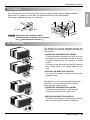
Step 1
Remove the air conditioner from it’s packaging and
slide the air conditioner out of it’s housing.
Step 2
Prepare the hole in the wall so that the bottom of
the housing is well supported, the top has minimum
clearace and the air inlet louveres have clearance
as shown. Holes from the outside through to the
cavity should be sealed. The housing should slope
down towards the rear by about 5mm to allow water
formed during operation to drain.
Step 3
Install the housing into the wall and secure. Ensure
the foam seals are not damaged. Flash, seal or fill
gaps around the inside and outside to provide
satisfactory appearance and protection against the
weather, insects and rodents.
Installation
Installation of the Housing
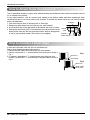
Installations of the unit into the Housing
Installations of the unit into the wall
1. Slide the unit into the housing until it is firmly
against the rear of the housing. Care is required
to ensure the foam sealing strips on the housing
remain in position.
2. Connect the air conditioner to the power and coil
excess cord length beneath the air conditioner
base or control box.
3. Engage the Chassis Lock into the bottom housing
rail and secure to the base with the screw
provided.
4. Remove the front panel from i’s carton and plastic
bag and fit as per the Operating Instruction.
5. Switch unit on. Check for operation of the unit
and check for vibration in the installation.
6. Fit the drain chute to the housing and run a drain
line to a suitable location if required.
NOTE: UNIT MAY BE SUPPORTED BY A
SOLID FRAME FROM BELOW OR
BY A HANGER FROM A SOLID
OVERHEAD SUPPORT.
FLASH OR SEAL AROUND EXTERNAL
WALL FRAME OR ARCHITRAVE
STURDY TIMBER
FRAME ALL ROUND
UNIT
DRAIN CHUTE
EXTERNAL SUPPORT
FRAME AT BALANCE
POINT OF RAC
Preferred method of installation into
a timber framed wall, partition or window.
ALTERNATIVELY, BRACKETS
AS ILLUSTRATED BELOW
MAY BE USED.
TIMBER FRAMED
WALL OR PARTITION
NOTICE
Alternative method of installation if external
support cannot be provided.
FLASH OR SEAL AROUND EXTERNAL
WALL FRAME OR ARCHITRAVE
ENSURE LOUVRES
ARE ENTIRELY
OUTSIDE THE WALL.
DRAIN CHUTE
STURDY TIMBER
FRAME
STEADYING BRACKET
(ONE PER SIDE)
SOLID TIMBER SUPPORT
TIMBER FRAMED
WALL OR PARTITION
100mm minimum
AIR IN
AIR IN
AIR IN
AIR OUT
OPTION A
100mm
100mm
LOUVRE
FRONT
45° BRICK CUT AWAY
TO CLEAR LOUVRES
45° BRICK CUT AWAY
TO CLEAR LOUVRES
BRICK
WALL
BRICK
WALL
AIR IN AIR IN
AIR OUT
TOP
VIEW
OPTION B

Owner’s Manual 11
ENGLISH
Installation
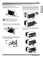
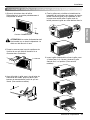
Install the Air Conditioner in the Case
1. Slide the air conditioner into the case.
Reinstall the 2 screws removed earlier on each
side of the case.
CAUTION:
The power cord must be
connected to an independent circuit.
The green wire must be grounded.
2. Stuff the foam between the top of the unit and the
wall to prevent air and insects from getting into the
room.
3. Before installing the front grille, pull out the vent
control lever located above the unit control knobs,
as shown. (for some models)
4. Attach the front grille to the case by inserting the
tabs on the grille into the slots on the front of the
case. Push the grille in until it snaps into place.
When you detach the front grille from the case,
push the grille to your right side and pull it toward
you.
5. Lift the inlet grill and secure the front grille with a
screw(L:10mm). Lower the inlet grille into place.
(for some models)
Power Cord
Screw
Screw
The Foam

12 Room Air Conditioner
Installation
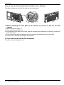
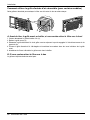
The grille is designed to clean the filter both upward and downward.
A. Before attaching the front grille to the cabinet, if you want to pull out the filter
upward;
1. Open the inlet grille slightly (a).
2. Turn inside out the front grille (a).
3. Disassemble the inlet grille from the front grille with separating the hinged part by inserting a straight type
screw-driver tip (b).
4. Then, rotate the inlet grille 180 degrees and insert the hooks into bottom holes of the front grille.
5. Insert the filter and attach the front grille to the cabinet.
B. If you want to pull out the filter downward;
The grille is already designed that way.
How to Use the Reversible Inlet Grille(For Some Models)
(b)
b
(a) (c)

Owner’s Manual 13
ENGLISH
Installation
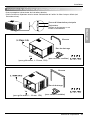
Circuit Breaker Installation and Parts for Installation
• Read thoroughly and follow all directions provided.
• A circuit breaker must be installed between the power source and the unit if the plug is not used
(see illustration below).
Main Power source
Circuit Breaker
Use a circuit breaker
or time delay fuse.

14 Room Air Conditioner
Operating Instructions
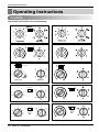
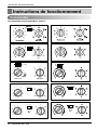
Operating Instructions
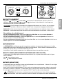
Controls
The controls will look like one of the following.
OFF
MED
FAN
HIGH
COOL
LOW
FAN
LOW COOL
MED
COOL
5
4
3
2
1
9
8
7
6
Auto Swing
OperationThermostat
On Off
OFF
MED
FAN
HIGH
COOL
LOW
FAN
LOW COOL
MED
COOL
5
4
3
2
1
9
8
7
6
OnOff
Auto Swing
OperationThermostat
OperationThermostat
Med
Fan
Off
Low
Fan
High
Cool
Med
Cool
Low Cool
6
7
8
9
5
1
2
3
4
Off On
Auto Swing

Owner’s Manual 15
ENGLISH
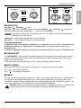
Operating Instructions
■ OPERATION
High Cool ( ), Med Cool ( ) and
Low Cool ( ) provide cooling with different fan speeds. Med Fan ( ) or Low Fan ( ) provides air
circulation and filtering without cooling. Off ( ) turns the air conditioner off.
If you move the switch from a cool setting to off or to a fan setting, wait at least 3 minutes before
switching back to a cool setting.
HIGH COOL : Permits cooling with the high fan speed operation.
LOW COOL : Permits cooling with the low fan speed operation.
Cooling Descriptions
For Normal Cooling- Select High Cool or Med Cool with the Operation knob at the midpoint of Thermostat knob.
For Maximum Cooling- Select High Cool with the Operation knob at the highest number available on your
Thermostat knob.
For Quieter & Nighttime Cooling- Select Low Cool with the Operation knob at the midpoint of Thermostat knob.
■ THERMOSTAT
The THERMOSTAT is used to maintain the room temperature. The compressor will cycle on and off to keep
the room at the same level of comfort. When you turn the knob to a higher number(the right side) and the
indoor air will become cooler.
The 5 or 6 position (the middle position of arc) is a normal setting for average conditions.
■ AUTO SWING
Auto swing switch controls the horizontal air direction by air swing system (not on all models).
ON ( ) : Auto swing is operated.
OFF ( ) : Auto swing is not operated.
■ TIMER
The timer can control the operation times within 12 hours. If you set the timer switch at the "1" position, after 1
hour the unit will be stopped automatically. If you want to operate continuously, set the timer switch at the
"CONSTANT" position. The timer switch cannot rotate further colckwise from the "CONSTANT" position. If you
set the timer switch at the "STOP" postion, the unit will be stopped all operations.
CAUTION:
When the air conditioner has been performed its cooling operation and is turned off or set
to the fan position, wait at least 3 minutes before resetting to the cooling operation again.
NOTICE
o
C
O
O
L
E
R
9
8
7
6
5
4
3
2
1
1
2
3
4
5
6
7
8
9
10
11
12
STOP
C
O
N
S
T
A
N
OPERATION
THERMOSTAT
AUTO SWING
TIMER
LOW
HIGH
OFF
ON

16 Room Air Conditioner
Operating Instructions
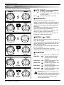
Controls
■ AUTO SWING (for some models)
ON ( ) : Air swing is operated while
OPERATION knob is set to the COOL
or HEAT position.
OFF ( ) : Stops the operation of air swing.
■THERMOSTAT
Turn the thermostat control to the desired
setting.The control position is a normal setting for
average conditions.You can change this setting, if
necessary, in accordance with your temperature
preference.
The thermostat automatically controls cooling or
heating, but the fan runs continuously
whenever the air conditioner is in operation. If the
room is too warm, turn the thermostat
control clockwise. If the room is too cool, turn the
thermostat control counterclockwise.
■ HEATER ( ) LAMP
When the unit sets heating operation condition, the
green lamp is lighted.
When the frost settles on the heat exchanger of the
outside, defrosting is made automatically and the
green lamp is turned off.
The unit may give a "hiss" and the fan motor stops
for 1 to 10 minutes.
This should not be regarded as a problem.
After defrosting, the heating operation begins again.
■ OPERATION
OFF ( ) : Turns the air conditioner off.
LOW FAN ( ) : Permits the low fan speed
operation without cooling
(heating).
LOW COOL ( ) : Permits cooling with the low
fan speed operation.
HIGH COOL ( ) : Permits cooling with the high
fan speed operation.
LOW HEAT ( ) : Permits heating with the low
fan speed operation.
HIGH HEAT ( ) : Permits heating with the high
fan speed operation.
CAUTION:
When the air conditioner has
been performed its cooling operation and is
turned off or set to the fan position, wait at
least 3 minutes before resetting to the
cooling operation again.
o
The controls will look like one of the following.
Thermostat
Warmer Cooler
Heater
Operation

Owner’s Manual 17
ENGLISH
Operating Instructions
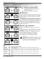
Remote Control
The remote control and control panel will look like one of the following pictures.
1. POWER
Operation starts when this button is pressed and stops when you press the button again.
2. OPERATION MODE SELECTOR
Heating function is only available in some models.
Select cooling mode to cool the room.
Select heating mode to heat the room.
Select fan mode for basic ventilating fan operation.
3. ON/OFF TIMER
The timer can be set to start and stop the unit in hourly increments (up to 12 hours).
Temperature increases only by 2°C and no longer increase thereafter.
3
4
1
3
55
4
1
22
3
4
1
3
55
4
1
22
1
52
4
3
7
1
52
4
3
7
1
7
5 64
2 3
1
7
5 64
2 3
1
7
54
2 3
1
7
54
2 3
66

18 Room Air Conditioner
Operating Instructions
4. FAN SPEED SELECTOR
For increased power while cooling or heating, select a higher fan speed.
Cooling Model: 3 steps{High[F3] ➔ Low[F1] ➔ Med[F2]
Heating Model: 2 steps{High[F2] ➔ Low[F1]
5. TEMPERATURE CONTROL
The thermostat monitors room temperature to maintain the desired temperature.
The thermostat can be set between 16°C~30°C (61°F~81°F).
The unit takes an average of 30 minutes to adjust the room temperature by 1°C (1.8°F).
6. AUTO SWING BUTTON (available in some models)
Allows the unit to automatically swing its louvers left and right during operation. If the option is de-
selected, the louvers will stop in their last position and orient the airflow in the corresponding direction.
7. REMOTE SENSOR
1. Push out the cover on the back of the remote control with your thumb
2. Pay attention to polarity and insert two new AAA 1.5V batteries.
3. Reattach the cover.
In case the power comes on again after a power failure, Auto Restarting Operation is the function to operate
procedures automatically to the previous operating conditions.
Do not use rechargeable batteries. Make sure that both batteries are
new.
• In order to prevent discharge, remove the batteries from the remote control if the
air conditioner is not going to be used for an extended period of time
Keep the remote control away from extremely hot or humid places.
To maintain optimal operation of the remote control, the remote sensor should not
be exposed to direct sunlight.
• The remote control can be mounted on a wall using the mountable holder.
NOTICE
Inserting the Remote Control Batteries
Auto Restart

Owner’s Manual 19
ENGLISH
Operating Instructions
Ventilation
Air Direction
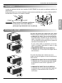
The ventilation lever must be in the CLOSE position in order to maintain the best cooling conditions.
When fresh air is necessary in the room, set the ventilation lever to the OPEN position.
The damper is opened and room air is drawn out.
Before using the ventilation feature,
position the lever, as shown. First, pull down
part to horizontal line with part .
NOTICE
The direction of air can be controlled wherever you
want to cool by adjusting the horizontal louver and the
vertical louver.
• HORIZONTAL AIR-DIRECTION CONTROL
To control horizontal direction of air flow, set to the
ON position the air-swing switch and the air flow will
be swept horizontally by the automatic air-swing
system.
If you want to stop the air flow from moving, switch off
the air swing switch at the desired position of the
vane.
• VERTICAL AIR-DIRECTION CONTROL
The vertical air direction is adjusted by moving the
horizontal louver.
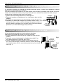
The direction of air can be controlled wherever
you want to cool by adjusting the horizontal
louver and the vertical louver.
• HORIZONTAL AIR-DIRECTION CONTROL
The horizontal air direction is adjusted by
rotating the vertical louver right or left.
• VERTICAL AIR-DIRECTION CONTROL
The vertical air direction is adjusted by rotating
the horizontal louver forward or backward.
Part A
Part B
VENTCLOSE OPEN

20 Room Air Conditioner
Operating Instructions
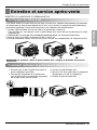
CABINET
DRAIN
PAN
DRAIN HOSE
SCREW
DRAIN PIPE
DRAIN HOSE
DRAIN PIPE
DRAIN ELBOW
DRAIN HOSE
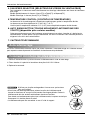
How to Attach Drain Pan(Optional)
How to Connect a Drain Hose
The air conditioner employs a proper drain method whereby the condensed water (moisture removed from the
air) is drained to the outside.
In very humid weather, (and for reverse cycle models in the reverse mode) excessive condensate water
removed from the air may cause some water to collect. To remove this excess water you can install the drain
pan as detailed below.
1. Take the drain pan which is located in the air discharge.
2. Remove the hole rubber from the base-pan (for some models).
3. Install the drain pan to the right corner of the cabinet with 4 (or 2) screws.
4. Connect the drain hose of 3/5" inside diameter to the outlet located at the
bottom of the drain pan.You can purchase the drain hose or tubing locally
to satisfy your particular needs. (Drain hose is not supplied).
A drain hole is provided at the rear of the air conditioner unit.
Select a drain method according to the following.
1. Remove the hole rubber from the base-pan. (for some models)
2. Connect a drain hose of
9
/
16
" inside diameter to the drain pipe as shown in
Fig. 1.
3. Or connect a pipe elbow of
9
/
16
" inside diameter to the drain pipe, then
connect a drain hose of
9
/
16
" inside diameter to the pipe elbow as shown in
Fig. 2.
Fig. 1
Fig. 2
La page est en cours de chargement...
La page est en cours de chargement...
La page est en cours de chargement...
La page est en cours de chargement...
La page est en cours de chargement...
La page est en cours de chargement...
La page est en cours de chargement...
La page est en cours de chargement...
La page est en cours de chargement...
La page est en cours de chargement...
La page est en cours de chargement...
La page est en cours de chargement...
La page est en cours de chargement...
La page est en cours de chargement...
La page est en cours de chargement...
La page est en cours de chargement...
La page est en cours de chargement...
La page est en cours de chargement...
La page est en cours de chargement...
La page est en cours de chargement...
La page est en cours de chargement...
La page est en cours de chargement...
La page est en cours de chargement...
La page est en cours de chargement...
La page est en cours de chargement...
La page est en cours de chargement...
La page est en cours de chargement...
-
 1
1
-
 2
2
-
 3
3
-
 4
4
-
 5
5
-
 6
6
-
 7
7
-
 8
8
-
 9
9
-
 10
10
-
 11
11
-
 12
12
-
 13
13
-
 14
14
-
 15
15
-
 16
16
-
 17
17
-
 18
18
-
 19
19
-
 20
20
-
 21
21
-
 22
22
-
 23
23
-
 24
24
-
 25
25
-
 26
26
-
 27
27
-
 28
28
-
 29
29
-
 30
30
-
 31
31
-
 32
32
-
 33
33
-
 34
34
-
 35
35
-
 36
36
-
 37
37
-
 38
38
-
 39
39
-
 40
40
-
 41
41
-
 42
42
-
 43
43
-
 44
44
-
 45
45
-
 46
46
-
 47
47


LG W246BH Le manuel du propriétaire
- Catégorie
- Climatiseurs split-system
- Taper
- Le manuel du propriétaire
dans d''autres langues
- English: LG W246BH Owner's manual
Documents connexes
-
LG LWC1264ABG Le manuel du propriétaire
-
-
-
LG LW-G0760BC Manuel utilisateur
-
-
-
-
-