
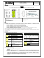
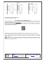
DIP Posizione Funzione
Switch1 ON Modalità Test
OFF Modalità normale (default)
Switch2 ON Supervisione disabilitata
OFF Supervisione abilitata (default)
Switch3
ON
Rivelatore rivolto verso uno spazio chiuso
(ad es. un muro più alto di una persona
entro 10 m dal rivelatore)
OFF
Rivelatore rivolto verso uno spazio aperto
(nessun muro entro 10 m di distanza)
(default)
Switch4
ON
Rivelatore rivolto verso una superficie che
non rilascia facilmente calore (ad es. un
prato) (default)
OFF
Rivelatore rivolto verso una superficie che
rilascia facilmente calore (ad es. in
cemento, o pietra o piastrellata)
DIP Livello di sensibilità
Switch5 Switch6
ON ON Basso; per animali di 75 cm / 60 kg
ON OFF Medio; per animali di 60 cm / 40 kg
OFF ON Alto; per animali di 45 cm / 30 kg
OFF OFF Superiore; per animali di 30 cm /
20 kg (default)
DIP
Posizion
e
Funzione
Switch7 ON Doppio rilevamento abilitato
(default)
OFF Doppio rilevamento disabilitato
Switch8 ON Riservato
OFF
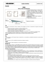
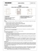
ITALIANO
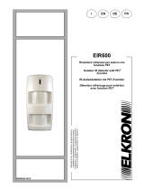
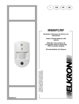
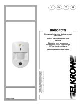
EIR600
RIVELATORE INFRAROSSI PER ESTERNO CON FUNZIONE PET
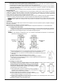
1. Pulsante Test e LED
2. Doppia lente
3. Alloggiamento delle batterie per due batterie al litio AA da 3,6 V.
4. Tamper antimanomissione
5. Blocco DIP Switch
6. Braccio della staffa
7. Staffa rotante
LED
In modalità di funzionamento normale, l'indicatore LED lampeggia per indicare la trasmissione del segnale nelle seguenti
situazioni.
Quando viene rilevato il movimento in condizioni di batteria scarica.
Quando viene aperto il coperchio e viene azionato l'interruttore tamper.
Quando viene rilevato movimento se persiste la condizione di manomissione.
Quando viene rilevato il movimento in modalità Test.
Quando viene premuto il pulsante Test in condizioni di manomissione o se la batteria del dispositivo è scarica.
Il LED non lampeggia se il tamper è chiuso e la batteria è carica e il rivelatore non è in modalità Test.
Il LED lampeggia per indicare trasmissione di segnale, lampeggiando rapidamente due volte alla ricezione della conferma
dall’unità di controllo.
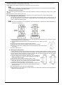
DIP Switch
La tabella seguente elenca la funzione di ogni DIP Switch. Il DIP Switch è in posizione ON oppure OFF. La posizione in alto indica
ON, mentre la posizione in basso indica OFF.
Apprendimento del rivelatore
Allentare le viti di fissaggio e rimuovere il coperchio.
A seconda delle proprie necessità, impostare l'interruttore di sensibilità come illustrato nella Tabella delle posizioni dei
DIP Switch.
Inserire due batterie al litio AA da 3,6 V nell'alloggiamento delle batterie, accertandosi di connettere la polarità
correttamente.
L'indicatore LED lampeggerà per 30 secondi. Il rivelatore è in fase di inizializzazione. Durante l’inizializzazione, il
rivelatore non è attivato. Si consiglia di non generare allarmi durante questo periodo. Una volta finito il periodo di
inizializzazione, il LED si spegne e il rivelatore è pronto per funzionare.
Mettere l’unità di controllo in modalità di apprendimento; per i dettagli, fare riferimento al manuale di istruzioni della unità
di controllo.
GUIDA RAPIDA
DS80IR2F-002A
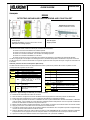
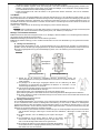
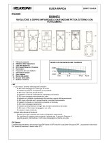
Diagramma di copertura
Altezza installazione / portata
H
Portata

Premere per circa 3 secondi il pulsante Test sul coperchio anteriore.
Se l’unità di controllo riceve il segnale, vengono visualizzate le informazioni corrispondenti. Per completare il processo
di apprendimento, fare riferimento al manuale di istruzioni della unità di controllo.
Una volta appreso il rivelatore, mettere l’unità di controllo in modalità Walk Test (Test movimento). Tenere il rivelatore
nella posizione desiderata, premere il pulsante Test per verificare che la posizione in questione si trovi nella portata di
copertura di comunicazione.
Una volta accertato che il rivelatore funzioni nella posizione desiderata, è possibile procedere all'installazione.
Modalità Walk Test
È possibile mettere il rivelatore in modalità Test per tre minuti premendo il pulsante Test una volta. Quando viene attivata la
modalità Test, il tempo di riposo del rivelatore, cioè il tempo che intercorre tra il rilevamento di un movimento e il movimento
successivo, è disabilitato e il led si accende per due secondi, confermando l’ingresso in modalità test. Per ulteriori dettagli sulla
funzione “Sleep Time” (tempo di riposo) si rimanda al manuale completo.
Il rivelatore esce automaticamente dalla modalità Test dopo tre minuti e ritorna in modalità normale. Per mettere il rivelatore in
modalità Test costante, posizionare il DIP Switch 1 facendo riferimento alla Tabella delle posizioni dei DIP Switch.
<
<N
NO
OT
TA
A>
>
In presenza di forte luce solare, è possibile che l’accensione del LED di test sia poco visibile. In tali casi si consiglia
di utilizzare la funzione di Walk Test e verificarne l’esito su App e portale ove disponibili e/o sugli apparati locali del sistema (ad
es. tastiere).
Installazione
Fase 1: Una volta eseguito il Walk Test per confermare che il rivelatore si trovi entro la portata di copertura, scegliere il montaggio
ad angolo o su superficie.
Fase 2: Allentare le viti di fissaggio e rimuovere il coperchio.
Fase 3: A seconda della preferenza dell'utente, montare il rivelatore nella posizione desiderata, con o senza staffa rotante.
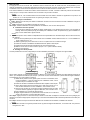
Montaggio senza staffa rotante:
La base posteriore del rivelatore è provvista di predisposizioni per i fori, dove la plastica è più sottile, per consentire il
montaggio. Due predisposizioni per i fori (A) servono per il fissaggio su superficie, mentre quattro predisposizioni per i
fori (C) servono per il fissaggio ad angolo, come illustrato nella figura seguente.
<
<N
NO
OT
TA
A>
>
Una volta perforate le predisposizioni per i fori, riverificare l'impermeabilità del dispositivo ed eventualmente
ripristinarla, per esempio con del silicone.
1) Perforare le predisposizioni per i fori sulla copertura della base. Per il montaggio su superficie,
usare le predisposizioni "A". Per il montaggio ad angolo, usare le predisposizioni "C".
2) Usando la dima per i fori, praticare due fori sulla superficie piana o quattro fori sulla superficie
dell'angolo.
3) Inserire i tasselli se si esegue il fissaggio su intonaco o mattoni.
4) Installare la copertura della base nei tasselli con la vite di montaggio in dotazione.
5) Riposizionare il coperchio superiore sulla base e premere saldamente la parte superiore fino
allo scatto (come illustrato a destra).
6) Stringere la vite di blocco.
Montaggio con staffa rotante:
Per consentire un'opzione di montaggio flessibile, viene fornita in dotazione una staffa rotante. Consiste in una staffa
rotante da fissare ad una superficie/ad un angolo e in un braccio della staffa
da fissare al rilevatore. Una volta installato, il rivelatore può essere separato
facilmente dalla staffa per sostituire le batterie, per esempio, e poi fissato
nuovamente con altrettanta facilità. Consente anche di regolare il rivelatore
orizzontalmente, per una migliore copertura.
1) Usare la staffa rotante come dima, praticare fori nel sito di montaggio a
seconda che sia una superficie o un angolo: 2 fori in posizione B per una
superficie, 4 fori in posizione D per un angolo.
2) Inserire i tasselli se si esegue il fissaggio su intonaco o mattoni.
3) Avvitare la staffa rotante nei tasselli con il lato piatto in direzione del muro. Il braccio della staffa deve essere rivolto
verso chi esegue il montaggio, con lo snodo in cima.
4) Stringere il braccio della staffa al coperchio della base del rivelatore con le estremità appuntite rivolte in direzione
opposta rispetto al rivelatore, con lo snodo in cima.
5) Sistemare il rivelatore sui ganci della staffa rotante.
Montaggio su
superficie
Montaggio ad
angolo
Vite di bloccaggio
Vite di bloccaggio

6) Regolare l'angolo di rilevamento sistemando il braccio della staffa su uno dei fori alla sommità della staffa rotante,
quindi stringere la vite superiore come illustrato.
Fase 4: Premere il pulsante Test una volta per entrare in modalità Test. Camminare all’interno dell'area protetta per accertarsi
che la copertura di rilevamento sia adeguata. Ogni volta che verrà rilevato un movimento, il LED si accenderà per due secondi a
conferma.
Fase 5: Quando si ritiene che la copertura di rilevamento sia soddisfacente, l'installazione è completata.
<
<N
NO
OT
TA
A>
>
Il rivelatore dispone di un alloggiamento rotante esterno che può essere regolato orizzontalmente, pertanto la sua
copertura di 110° può variare da 0° a 180°.
Frequenza radio di utilizzo: 868,6 - 868,7 MHz
Potenza radio trasmessa: 8,55 dBm
DICHIARAZIONE DI CONFORMITÀ UE SEMPLIFICATA
Il fabbricante, URMET S.p.A., dichiara che il tipo di apparecchiatura radio: RIVELATORE INFRAROSSI PER ESTERNI CON
FUNZIONE PET EIR600 è conforme alla direttiva 2014/53/UE. Il testo completo della dichiarazione di conformità UE è disponibile
al seguente indirizzo Internet: www.elkron.com.
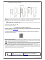
CLICCARE SUL SEGUENTE LINK DEL SITO ELKRON PER ACCEDERE ALLA SCHEDA TECNICA DEL PRODOTTO E
SCARICARE IL MANUALE COMPLETO
DIRETTIVA 2012/19/UE DEL PARLAMENTO EUROPEO E DEL CONSIGLIO del 4 luglio 2012 sui rifiuti di apparecchiature
elettriche ed elettroniche (RAEE).
Il simbolo del cassonetto barrato riportato sull’apparecchiatura o sulla sua confezione indica che il prodotto alla fine
della propria vita utile deve essere raccolto separatamente dagli altri rifiuti.
L’utente dovrà, pertanto, conferire l’apparecchiatura giunta a fine vita agli idonei centri comunali di raccolta differenziata
dei rifiuti elettrotecnici ed elettronici. In alternativa alla gestione autonoma è possibile consegnare l’apparecchiatura che
si desidera smaltire al rivenditore, al momento dell’acquisto di una nuova apparecchiatura di tipo equivalente.
Presso i rivenditori di prodotti elettronici con superficie di vendita di almeno 400 m2 è inoltre possibile consegnare gratuitamente,
senza obbligo di acquisto, i prodotti elettronici da smaltire con dimensione massima inferiore a 25 cm.
L’adeguata raccolta differenziata per l’avvio successivo dell’apparecchiatura dismessa al riciclaggio, al trattamento e allo
smaltimento ambientalmente compatibile contribuisce ad evitare possibili effetti negativi sull’ambiente e sulla salute e favorisce il
reimpiego e/o riciclo dei materiali di cui è composta l’apparecchiatura.
ELKRON
Tel. +39 011.3986711 - Fax +39 011.3986703
www.elkron.com – mail to: info@elkron.it
ELKRON è un marchio commerciale di URMET S.p.A.
Via Bologna 188/C – 10154 Torino (TO) Italia
HUwww.urmet.comUH
MADE IN TAIWAN
Vite superiore
Braccio
staffa
S
taffa
rotante

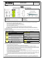
DIP Sensitivity level
Switch5 Switch6
ON ON Low; for 75 cm / 60 kg animals
ON OFF
position Medium; for 60 cm / 40 kg animals
OFF
position ON High; for 45 cm / 30 kg animals
OFF
position
OFF
position
Higher; for 30 cm / 20 kg animals
(default)
DIP Position Function
Switch7 ON Double detection on (default)
OFF
position
Double detection off
Switch8 ON Reserved
OFF
DIP Position Function
Switch1 ON Test mode
OFF
position
Normal mode (default)
Switch2 ON Supervision off
OFF
position
Supervision on (default)
Switch3
ON Detector facing a closed space (eg a wall higher
than a person within 10 m of the detector)
OFF Detector facing an open space (no wall within
10 m of the detector) (default)
Switch4
ON Detector facing a surface that does not easily
release heat (eg a lawn) (default)
OFF
position
Detector facing a surface that easily releases
heat (eg in cement, or stone or tiled)
ENGLISH
EIR600
OUTDOOR IR DETECTOR WITH PET FUNCTION
1. Test button and LED
2. Double sensor
3. Battery housing for two AA 3.6 V lithium batteries.
4. Tamper switch
5. DIP Switch block
6. Bracket arm
7. Rotating bracket
LED
In normal operating mode, the LED indicator blinks to indicate that signals are being transmitted in the following situations.
When movement is detected in flat battery conditions.
When the cover is opened and the tamper switch is actuated.
When movement detected if the tamper alarm condition persists.
When motion is detected in Test mode.
When the Test button is pressed in tampering conditions or if the battery of the device is flat.
The LED does not blink if the tamper switch is closed, the battery is charged and the detector is not in Test mode.
The LED blinks to indicate signal transmission, blinking rapidly twice upon receiving confirmation from the control unit.
DIP Switch position table
The function of each DIP Switch is listed in the following table. The DIP Switch is in position ON or OFF. Position up indicates
ON, position down indicates OFF.
Preparation – Learning of the detector by the control unit
Loosen the screws and remove the cover.
Set the sensitive switch as needed as shown in the DIP Switch position table.
Insert two AA 3.6 V lithium batteries in the battery housing ensuring that the polarity is correctly connected.
The LED indicator will blink for 30 seconds. The detector is being initialised. During initialisation, the detector will not be
active. It is advisable not to generate any alarms during this time. Once the initialisation time has finished, the LED will
switch off and the detector is ready to start working.
Set the control unit to learning mode; see the instruction manual of the control unit for details.
Hold the Test button on the front cover pressed for about 3 seconds.
The corresponding information is displayed if the control unit receives the signal. Refer to the instruction manual of the
control unit to complete the learning process.
Put the control unit in Walk Test mode (motion Test) after the detector learning procedure. Hold the detector in the
required position, press the Test button to check that the concerned position is within the communication coverage range.
Proceed with the installation after having ascertained that the detector is working in the desired position.
Test mode
The detector can be set to Test mode for three minutes by pressing the Test button once. In Test mode, the sleep time is off
and the LED indicator lights up for two seconds, independently from motion detection. The detector automatically exits Test
QUICK GUIDE
DS80IR2F-002A
Coverage diagram
Installation height / Range

mode after three minutes and goes back to normal mode. In order to set the detector to constant Test mode, positioning the
DIP Switch 1 the reference to the DIP Switch position table.
SLEEP TIME
time between the detection of a movement and the next movement
<
<N
NO
OT
TE
E>
>
In such cases it is advisable to use the Walk Test function and check the outcome on the App and portal where available
and / or on the system's local devices (eg keyboards).
Mounting and installation method
Step 1: After having performed the Walk Test to confirm that the detector is within the coverage range, select corner or surface
mounting.
Step 2: Loosen the screws and remove the cover.
Step 3: According to the user's preferences, mount the detector in the required position with or without rotating bracket.
Mounting without rotating bracket:
The rear base of the detector is provided with a hole arrangement when the plastic is thinner to allow mounting. The
two hole arrangements (A) are used to fix on a surface while the four hole arrangements (C) are used for fixing in a
corner, as shown in the following figure.
<
<N
NO
OT
TE
E>
>
After having perforated the hole arrangements, check that the device is waterproof and restore waterproofing, if
necessary, e.g. with silicone.
1) Perforate the appropriate hole arrangements on the cover of the base. Use arrangements "A" for mounting on surface.
Use arrangements "C" for mounting in corner.
2) Using the template for the hole,make two holes in the flat surface or four holes in the corner
surface.
3) Insert the anchor bolts if the device is fixed to plaster or bricks.
4) Install the base cover in the anchor bolt with the mounting screws provided.
5) Reposition the upper cover on the base and firmly press the upper part until it clicks (as shown
on the right).
6) Tighten the locking screw.
Mounting with rotating bracket:
A rotating bracket is provided to allow a flexible mounting option. This allows a rotating bracket to be fixed to a surface/in
a corner and to an arm of the bracket to be fixed to the detector. Once installed, the detector may be separated easily
from the bracket to replace the batteries, for example, and then fixed back again with equal ease. This also makes it
possible to adjust the horizontal detector for better coverage.
1) Using the rotating shaft as template, make holes in the mounting site,
either on a surface or in a corner: 2 holes in position B for a surface, 4
holes in position D for an angle.
2) Insert the anchor bolts if the device is fixed to plaster or bricks.
3) Fasten the rotating bracket in the anchor bolts with the flat side in direction
of the wall. The arm of the bracket must face towards the person
performing the mounting operation, with the joint on top.
4) Fasten the arm of the bracket to the cover of the base of the detector with
the pointy ends facing the opposite directions with respect to the detector,
with the joint on top.
5) Arrange the detector on the hooks of the rotating bracket.
6) Adjust the detection angle arranging the arm of the bracket on one of the holes of the top of the rotating bracket then
tighten the top screw as shown.
Surface
mounting Corner
mounting
Fastening screw
Fastening screw

Step 4: Press the Test button once to enter Test mode. Walk inside the protected area to make sure that the detection coverage
is suitable. The LED will light up for two seconds to confirm whenever a movement is detected.
Step 5: Installation is complete when the detection coverage is appropriate.
<
<N
NO
OT
TE
E>
>
The detector has an external rotating housing which may be adjusted horizontally and consequently its 110°
coverage can vary from 0° to 180°.
Radio frequency of use: 868,6 - 868,7 MHz
Radio power transmitted: 8,55 dBm
SIMPLIFIED EU DECLARATION OF CONFORMITY
Hereby, URMET S.p.A. declares that the radio equipment type: OUTDOOR IR DETECTOR WITH PET FUNCTION EIR600 is in
compliance with Directive 2014/53/EU. The full text of the EU declaration of conformity is available at the following internet
address: www.elkron.com.
CLICK ON THE FOLLOWING LINK OF THE ELKRON SITE TO ACCESS THE PRODUCT TECHNICAL SHEET AND
DOWNLOAD THE COMPLETE MANUAL:
DIRECTIVE 2012/19/EU OF THE EUROPEAN PARLIAMENT AND OF THE COUNCIL of 4 July 2012 on waste electrical and
electronic equipment (WEEE).
The symbol of the crossed-out wheeled bin on the product or on its packaging indicates that this product must not be
disposed of with your other household waste.
Instead, it is your responsibility to dispose of your waste equipment by handing it over to a designated collection point
for the recycling of waste electrical and electronic equipment. The separate collection and recycling of your waste equipment at
the time of disposal will help to conserve natural resources and ensure that it is recycled in a manner that protects human health
and the environment.
For more information about where you can drop off your waste equipment for recycling, please contact your local city office,
your household waste disposal service or the shop where you purchased the product.
ELKRON
Tel. +39 011.3986711 - Fax +39
011.3986703
www.elkron.com – mail to: info@elkron.it
ELKRON is a trademark of URMET S.p.A.
Via Bologna 188/C – 10154 Turin (TO) Italy
HUwww.urmet.comUH
MADE IN TAIWAN

FRANÇAIS
EIR600
DÉTECTEUR INFRAROUGE POUR EXTÉRIEUR AVEC FONCTION PET
1. Touch Test et voyant LED
2. Double optique
3. Logement des batteries. Pour deux piles au lithium AA 3,6V
4. Interrupteur anti-sabotage (tamper)
5. Bloc de micro-interrupteurs (DIP-switch)
6. Bras de support
7. Support pivotant
Voyant LED
En fonctionnement normal, la LED ne s'allume pas, sauf dans les cas suivants :
Quand le mouvement est détecté avec batterie épuisée.
Quand le couvercle est ouvert et le interrupteur anti-sabotage est activé.
Quand un mouvement est détecté, si la condition de sabotage persiste.
Quand un mouvement est détecté en mode Test.
Quand on appuie sur la touche Test dans des conditions de sabotage ou si la batterie du dispositif est épuisée.
La LED ne clignote pas si l’interrupteur anti-sabotage est fermé, la batterie est épuisée et le détecteur n’est pas en mode Test.
La LED clignote pour montrer la transmission d’un signal et clignote vite deux fois quand elle reçoit un signal de confirmation de
la centrale.
Table des positions des micro-interrupteurs (DIP-switch)
La table suivante montre la fonction de chaque DIP switch. Celui-ci peut être en position ON ou OFF. La position en haut
correspond à ON, la position en bas à OFF.
Préparation – Apprentissage du détecteur par l’unité de contrôle
Desserrer les vis de fixation et enlever le couvercle.
Selon les besoins, configurer le niveau de sensibilité comme expliqué dans la Table des positions des DIP Switch.
Insérer deux piles au lithium AA 3,6 V dans le logement des batteries, en respectant la polarité.
La LED clignotera pendant 30 secondes. Le détecteur est alors en phase d’initialisation. Pendant l’initialisation, le détecteur
n’est pas activé. Il est conseillé de ne pas déclencher d’alarmes pendant cette période. Une fois la période d’initialisation
terminée, la LED s’éteint et le détecteur est prêt à fonctionner.
Mettre l’unité de contrôle en mode d’apprentissage ; pour les détails, consulter le manuel d’instructions de l’unité de contrôle.
Appuyer pour environ 3 secondes sur la touche Test sur le couvercle frontal.
Si l’unité de contrôle reçoit le signal, les informations relatives sont affichées. Pour compléter la procédure d’apprentissage,
consulter le manuel d’instructions de l’unité de contrôle.
Quand le détecteur a été acquis, mettre l’unité de contrôle en mode Test radio (test de mouvement). Maintenir le détecteur
à l’emplacement voulu, appuyer sur la touche Test pour vérifier si cet emplacement est couvert par l’unité de contrôle
Après avoir vérifié que le détecteur fonctionne à l’emplacement voulu, poursuivre l’installation.
GUIDE RAPIDE
DS80IR2F-002A
DIP
Position
Fonction
Switch1
ON
Mode Test Radio
OFF
Mode normal (par défaut)
Switch2
ON
Supervision désactivée
OFF
Supervision activée (par défaut)
Switch3
ON
Détecteur tourné vers le mur
OFF Détecteur tourné vers un espace
ouvert (aucun mur à 10 m de
distance) (par défaut)
Switch4
ON Détecteur tourné vers une pelouse
(par défaut)
OFF Détecteur tourné vers un sol en
béton/pierre
DIP
Niveau de sensibilité
Switch5
Switch6
ON ON Bas ; pour animaux de 75 cm / 60 kg
ON OFF Moyen ; pour animaux de 60 cm / 40 kg
OFF ON Haut ; pour animaux de 45 cm / 30 kg
OFF OFF Max ; pour animaux de 30 cm / 20 kg
(par défaut)
DIP
Position
e
Fonction
Switch7 ON Double détection activée (par défaut)
OFF
Double détection désactivée
Switch8 ON
Réservé
OFF
Diagramme de couverture
Hauteur d'installation / Portée

Mode Test radio
En appuyant une fois sur la touche Test, le détecteur entre en mode Test radio. En mode Test radio, le temporisateur (voir ci-
dessous) est désactivé et l’indicateur LED s’allume pendant deux secondes, sans tenir compte de la détection d’un mouvement.
Le détecteur sort du mode Test automatiquement au bout de trois minutes et revient en mode normal.
Pour mettre le détecteur en mode Test constant, mettre le DIP switch 1 sur ON ; consulter la Table des positions des DIP switch.
Temps de repos
temps entre la détection d'un mouvement et le prochain mouvement.
<
<N
NO
OT
TE
E>
>
Dans de tels cas, il est conseillé d'utiliser la fonction Walk Test et de vérifier le résultat sur l'application et le portail, le cas
échéant, et / ou sur les dispositifs locaux du système (par exemple, des claviers).
Méthode de montage et d’installation
Ière étape : Effectuer le Test radio pour vérifier si le détecteur est dans la zone de couverture et choisir l’installation en angle ou
sur une surface plane.
IIème étape : Desserrer les vis de fixation et enlever le couvercle.
IIIème étape : Installer le détecteur suivant la préférence de l’utilisateur, avec ou sans l’étrier pivotant.
Installation sans étrier pivotant
La face arrière du détecteur est dotée de parties prédécoupées, où le plastique est plus mince, pour permettre le
montage. Deux trous prédécoupés (A) sont utilisés pour l’installation murale, les quatre trous (C) pour l’installation en
angle, comme illustré dans la figure suivante.
<
<N
NO
OT
TE
E>
>
Après avoir percé le trous, vérifier si le dispositif est encore imperméable et si nécessaire remplir les trous avec du silicone,
par exemple.
1) Percer les trous prédécoupés sur la face arrière. Pour l’installation murale, utiliser les trous « A ». Pour l’installation en
angle, utiliser les trous « C ».
2) Utiliser le gabarit pour percer deux trous sur le mur ou quatre trous sur la surface de l’angle.
3) Insérer les chevilles si l’installation est effectuée dans du plâtre ou des briques.
4) Installer la face arrière dans les chevilles avec la vis de montage fournie.
5) Mettre le couvercle sur la face et enfoncer jusqu’au « clic » (comme illustré à droite).
6) Serrer la vis de blocage.
Montage avec étrier pivotant
Un étrier pivotant est fourni avec le dispositif pour rendre l’installation plus flexible. Il comprend un support rotatif à
fixer à plat/en angle et un bras de support à fixer au détecteur. Une fois installé, le détecteur peut être détaché facilement de
l’étrier - pour remplacer les batteries, par exemple - puis fixé de nouveau aussi facilement. Il permet aussi de régler le détecteur
horizontalement, pour une meilleure couverture.
1) Utiliser l’étrier pivotant comme gabarit, percer les trous où nécessaire, selon
le type d’installation : 2 trous en position B pour l’installation murale, 4 trous
en position D pour l’installation en angle.
2) Insérer les chevilles si l’installation est effectuée dans du plâtre ou des briques.
3) Visser l’étrier pivotant dans les chevilles avec le côté plat contre le mur. Le
bras de l’étrier doit être tourné vers l’installateur, avec la rotule en haut.
4) Serrer le bras de l’étrier au couvercle de la base du détecteur avec les côtés
pointus en direction opposée par rapport au détecteur, avec la rotule en haut.
5) Fixer le détecteur aux crochets de l’étrier pivotant.
6) Régler l’angle de détection en positionnant le bras de l’étrier sur l’un des deux trous au sommet de l’étrier pivotant et
serrer la vis supérieure, comme illustré dans la figure.
IVème étape : Appuyer une fois sur la touche Test pour entrer en mode Test. Se déplacer à l’intérieur de la zone à protéger pour
vérifier si la couverture est appropriée. Chaque fois qu’un mouvement est détecté la LED s’allumera pendant deux secondes pour
confirmer.
Vème étape : Quand le champ de couverture de détection est considéré comme suffisant, l’installation est terminée.
<
<N
NO
OT
TE
E>
>
Le détecteur est doté d’un logement pivotant interne qui peut être réglé horizontalement ; sa couverture de 110° peut donc
changer de 0° à 180°.
Installation
murale
Installation en
angle
Vis de blocage Vis de blocage

Fréquence radio d'utilisation : 868,6 - 868,7 MHz
Puissance radio transmise : 8,55 dBm
DECLARATION UE DE CONFORMITÉ SIMPLIFIÉE
Le fabricant, URMET S.p.A., déclare que l’équipement radio : DÉTECTEUR INFRAROUGE POUR EXTÉRIEUR AVEC
FONCTION PET EIR600 est conforme à la directive 2014/53/UE. Le texte complet de la déclaration UE de conformité est
disponible à l’adresse internet suivant : www.elkron.com.
CLIQUEZ SUR LE LIEN SUIVANT DU SITE ELKRON POUR ACCÉDER À LA FICHE TECHNIQUE DU PRODUIT ET
TÉLÉCHARGER LE MANUEL COMPLET :
LES BONS GESTES DE MISE AU REBUT DE CE PRODUIT (Déchets d’équipements électriques et électroniques)
Ce symbole apposé sur le produit, ses accessoires ou sa documentation indique que ni le produit, ni ses accessoires
électroniques usagés (chargeur, casque audio, câble USB, etc.), ne peuvent être jetés avec les autres déchets
ménagers.
La mise au rebut incontrôlée des déchets présentant des risques environnementaux et de santé publique, veuillez
séparer vos produits et accessoires usagés des autres déchets. Vous favoriserez ainsi le recyclage de la matière qui les compose
dans le cadre d’un développement durable.
ELKRON
Tel. +39 011.3986711 - Fax +39 011.3986703
www.elkron.com – mail to: info@elkron.it
ELKRON est une marque commerciale de URMET S.p.A.
Via Bologna 188/C – 10154 Turin (TO) Italie
www.urmet.com
Vis supérieure
Etrier
pivotant
Bras
étrier
MADE IN TAIWAN

DIP
Position
Funktion
Switch1 ON Test-Modus
OFF Normale Betriebsart (Standard)
Switch2 ON Überwachung deaktiviert
OFF
Überwachung aktiviert (Standard)
Switch3
ON
Detektor, der auf einen geschlossenen Raum
gerichtet ist (z. B. eine Wand höher als eine
Person innerhalb von 10 m vom Detektor)
OFF
Detektor, der auf einen offenen Raum
gerichtet ist (keine Wand innerhalb von 10 m
vom Detektor) (Standard)
Switch4
ON
Detektor, der auf eine Oberfläche gerichtet ist,
die nicht leicht Wärme abgibt (z. B. Rasen)
(Standard)
OFF
Detektor, der auf eine Oberfläche gerichtet
ist, die leicht Wärme abgibt (z. B. in Zement,
Stein oder Fliesen)
DEUTSCH
EIR600
IR-AUßENDETEKTOR MIT PET-FUNKTION
1. Test-Taste und LED-Anzeige
2. Doppelter Sensor
3. Batteriefach für zwei 3,6 V-Lithium-Batterien Typ AA.
4. Tamper-Schalter als Sabotageschutz
5. Dip-Switch-Block
6. Ausleger der Halterung
7. Drehhalterung
LED
In der normalen Betriebsart blinkt die LED-Anzeige, um die Signalübertragung in den folgenden Situationen anzuzeigen.
Wenn die Bewegung bei entladener Batterie erfasst wird.
Wenn die Abdeckung geöffnet und der Tamper-Schalter betätigt wird.
Wenn die Bewegung bei anhaltender Sabotagebedingung erfasst wird.
Wenn die Bewegung im Test-Modus erfasst wird.
Wenn die Test-Taste bei Sabotagebedingung betätigt wird oder die Batterie der Vorrichtung entladen ist.
Die LED blinkt nicht, wenn der Tamper geschlossen und die Batterie geladen ist und der Detektor sich nicht im Test-Modus
befindet.
Die LED blinkt, um die Signalübertragung anzuzeigen, indem beim Empfang der Bestätigung über die Schalttafel ein schnelles
zweimaliges Blinken erfolgt.
Tabelle der Positionen der DIP-Switches
Die folgende Tabelle gibt die Funktion jedes DIP-Switches an. Der DIP-Switch befindet sich entweder in Position ON oder OFF.
Die Position oben gibt ON an, während die Position unten OFF angibt.
Vorbereitung - Einlernen des Detektors von Seiten des Steuergeräts
Die Befestigungsschrauben lösen und die Abdeckung entfernen.
Entsprechend den jeweiligen Bedürfnissen den Empfindlichkeitsschalter einstellen wie in der Tabelle der Positionen der
DIP-Switches angegeben.
Zwei 3,6 V-Lithium-Batterien Typ AA in das Batteriefach einsetzen und sich vergewissern, dass die Polarität korrekt
angeschlossen wird.
Die LED-Anzeige blinkt 30 Sekunden lang auf. Der Detektor befindet sich in der Initialisierungsphase. Während der
Initialisierung wird der Detektor nicht aktiviert. Es wird empfohlen, während dieses Zeitraums keine Alarme zu
generieren. Sobald die Initialisierungszeit beendet ist, schaltet sich die LED aus und der Detektor ist betriebsbereit.
Das Steuergerät in den Einlernmodus bringen. Wegen Einzelheiten hierzu beziehen Sie sich bitte auf die
Bedienungsanleitung des Steuergeräts.
Drücken Sie die Test-taste an der vorderen Abdeckung etwa 3 Sekunden lang
Wenn das Steuergerät das Signal empfängt, werden die entsprechenden Informationen eingeblendet. Zum Abschließen
SCHNELLANLEITUNG
DS80IR2F-002A
DIP Empfindlichkeitsstufe
Switch5 Switch6
ON ON Niedrig; für Tiere mit 75 cm / 60 kg
ON OFF Mittel; für Tiere mit 60 cm / 40 kg
OFF ON Hoch; für Tiere mit 45 cm / 30 kg
OFF OFF Höher; für Tiere mit 30 cm / 20 kg
( Standard )
DIP Position Funktion
Switch7 ON Doppelte Erfassung aktiviert
(Standard)
OFF Doppelte Erfassung deaktiviert
Switch8 ON Reserviert
OFF
Abdeckungsdiagramm
Höhe Installation / Infrarotreichweite

des Einlernvorgangs auf die Bedienungsanleitung des Steuergeräts Bezug nehmen.
Sobald der Detektor eingelernt wurde, das Steuergerät in den Walk Test-Modus (Bewegungstest) versetzen. Den
Detektor in der gewünschten Position halten und die Taste Test betätigen, um zu überprüfen, ob die jeweilige Position
sich in Reichweite des Kommunikationsempfangs befindet.
Sobald sichergestellt wurde, dass der Detektor in der gewünschten Position funktioniert, kann mit der Installation
begonnen werden.
Test-Modus
Der Detektor kann durch einmaliges Betätigen der Test-Taste drei Minuten lang in den Test-Modus versetzt werden. Im Test-
Modus ist die Ruhezeit-Timer deaktiviert und die LED-Anzeige leuchtet unabhängig vom Erfassen einer Bewegung zwei Sekunden
lang auf. Der Detektor verlässt den Test-Modus nach drei Minuten automatisch und kehrt zur normalen Betriebsart zurück. Um
den Detektor dauerhaft in den Test-Modus zu versetzen, den DIP-Switch 1 unter Bezugnahme auf die Tabelle der Positionen der
DIP-Switches positionieren.
Ruhezeit-Timer
Zeit zwischen der Erkennung einer Bewegung und der nächsten Bewegung.
<
<H
HI
IN
NW
WE
EI
IS
S>
>
In solchen Fällen empfiehlt es sich, den Walk Test-Funktion zu verwenden und das Ergebnis in der App und im Portal (sofern
verfügbar) und / oder auf der lokalen Ausrüstung des Systems (z. B. Tastaturen) zu überprüfen.
Montage- und Installationsmethode
Schritt 1: Sobald der Walk Test durchgeführt wurde, um zu bestätigen, dass der Detektor sich im Abdeckungsbereich befindet,
die winklige oder die Oberflächenmontage wählen.
Schritt 2: Die Befestigungsschrauben lösen und die Abdeckung entfernen.
Schritt 3: Den Detektor abhängig von den Vorlieben des Benutzers mit oder ohne Drehhalterung in der gewünschten Position
montieren.
Montage ohne Drehalterung:
Die hintere Basis des Detektors ist, dort, wo der Kunststoff dünner ist, für die Bohrungen ausgelegt, um die Montage zu
gestatten. Zwei für die Bohrungen ausgelegte Bereiche (A) dienen der Befestigung auf Oberflächen, während vier für die
Bohrungen ausgelegte Bereiche (C) der Winkelbefestigung dienen, wie in der Abbildung im Anschluss dargestellt.
<
<H
HI
IN
NW
WE
EI
IS
S>
>
Sobald die für die Bohrungen ausgelegten Bereiche durchbrochen wurden, die
Undurchlässigkeit der Vorrichtung erneut überprüfen und eventuell, z. B. mit Hilfe von Silikon,
wieder herstellen.
1) Die jeweiligen für die Bohrungen ausgelegten Bereiche auf der Abdeckung der Basis
durchbrechen. Für die Montage auf Oberflächen die Bereiche "A" verwenden. Für die
Winkelmontage die Bereiche "C" verwenden.
2) Unter Verwendung der Bohrschablone zwei Bohrungen auf der flachen Oberfläche oder vier
Bohrungen auf der Winkeloberfläche anbringen.
3) Die Dübel einsetzen, wenn die Befestigung auf Verputz oder Ziegeln erfolgt.
4) Die Abdeckung der Basis in den Dübeln mit der im Lieferumfang enthaltenen Montageschraube installieren.
5) Die oberen Abdeckung wieder auf der Basis anbringen und den oberen Teil bis zum Einrasten fest andrücken (wie
rechts veranschaulicht).
6) Die Befestigungsschraube anziehen.
Montage mit Drehalterung:
Um eine flexible Montageoption zu ermöglichen, ist im Lieferumfang eine Drehhalterung enthalten. Sie besteht aus einer
an einer Oberfläche/in einem Winkel zu befestigenden Drehhalterung und aus einem am Detektor zu befestigenden
Ausleger der Halterung. Nach der Installation kann der Detektor mühelos von der Halterung getrennt werden, z. B. um die
Batterien auszuwechseln, und dann ebenso problemlos wieder angebracht werden. Auch die horizontale Ausrichtung des
Detektors für eine bessere Abdeckung wird damit ermöglicht.
1) Die Drehhalterung als Schablone verwenden und die Bohrungen an der Montagestelle entsprechend der Oberfläche
oder des Winkels anbringen: 2 Bohrungen in Position B für eine Oberfläche, 4 Bohrungen in Position D für einen
Winkel.
2) Die Dübel einsetzen, wenn die Befestigung auf Verputz oder Ziegeln
erfolgt.
3) Die Drehhalterung mit der flachen Seite zur Wand in den Dübeln
verschrauben. Der Ausleger der Halterung muss mit dem Gelenk nach
oben zu der die Montage ausführenden Person gerichtet sein.
4) Den Ausleger der Halterung an der Abdeckung der Basis des Detektors
mit den spitzen Enden in entgegengesetzter Richtung zum Detektor und
dem Gelenk nach oben verschrauben.
Montage auf
Oberflächen Winkelmontage
Befestigungsschraube
Befestigungsschraube

5) Den Detektor auf den Haken der Drehhalterung anbringen.
6) Den Erfassungswinkel durch Anbringen des Auslegers der Halterung auf einer der Bohrungen oben an der
Drehhalterung einstellen und dann die oberen Schraube wie dargestellt anziehen.
Schritt 4: Die Test-Taste einmal betätigen, um sich in den Test-Modus zu begeben. Sich innerhalb des
geschützten Bereichs bewegen, um sicherzustellen, dass der Abdeckungsbereich der Erfassung angemessen
ist. Bei jeder Bewegungserfassung schaltet sich die LED zur Bestätigung zwei Sekunden lang ein.
Schritt 5: Wird beschlossen, dass die Erfassungsabdeckung zufriedenstellend ist, ist die Installation abgeschlossen.
<
<H
HI
IN
NW
WE
EI
IS
S>
>
Der Detektor verfügt über eine externen drehbaren Sitz, der horizontal eingestellt werden kann, daher kann seine
Abdeckung von 110° von 0° bis 180° variieren.
Radiofrequenz der Nutzung: 868,6 - 868,7 MHz
Übertragene Funkleistung: 8,55 dBm
VEREINFACHTE EU-KONFORMITÄTSERKLÄRUNG
Der Hersteller, URMET S.p.A., erklärt, dass der Funkgerätetyp: IR-AUßENDETEKTOR MIT PET-FUNKTION EIR600 der
Richtlinie 2014/53/UE entspricht. Der ungekürzte Text der EU-Konformitätserklärung steht unter der folgenden Internetadresse
zur Verfügung: www.elkron.com
KLICKEN SIE AUF DEN FOLGENDEN LINK DER ELKRON-WEBSITE, UM AUF DAS TECHNISCHE DATENBLATT
ZUZUGREIFEN UND DAS VOLLSTÄNDIGE HANDBUCH HERUNTERZULADEN:
KORREKTE ENTSORGUNG VON ALTGERÄTEN (Elektroschrott)
Diese Kennzeichnung auf dem Produkt, den Zubehörteilen oder der Dokumentation weist darauf hin, dass das Produkt
und die elektronischen Zubehörteile nicht mit anderem Hausmüll entsorgt werden dürfen.
Entsorgen Sie dieses Gerät und Zubehörteile bitte getrennt von anderen Abfällen, um der Umwelt bzw. der menschlichen
Gesundheit nicht durch unkontrollierte Müllbeseitigung zu schaden. Helfen Sie mit, das Altgerät und Zubehörteile
fachgerecht zu entsorgen, um die nachhaltige Wiederverwertung von stofflichen Ressourcen zu fördern.
ELKRON
Tel. +39 011.3986711 - Fax +39 011.3986703
www.elkron.com – mail to: info@elkron.it
ELKRON ist ein eingetragenes Warenzeichen von
URMET S.p.A.
Via Bologna 188/C – 10154 Torino (TO) Italy
www.urmet.com
Obere Schraube
Ausleger
Halterung
MADE IN TAIWAN
Drehh
alterung
-
 1
1
-
 2
2
-
 3
3
-
 4
4
-
 5
5
-
 6
6
-
 7
7
-
 8
8
-
 9
9
-
 10
10
-
 11
11
-
 12
12


dans d''autres langues
- italiano: Elkron EIR600 Guida Rapida
- English: Elkron EIR600 Quick start guide
- Deutsch: Elkron EIR600 Schnellstartanleitung
Documents connexes
-
 Elkron EIR600 Guide d'installation
-
 Elkron IR600 Guide de démarrage rapide
-
 Elkron IRT600 Guide de démarrage rapide
-
 Elkron EIR600FC Guide de démarrage rapide
-
 Elkron EIR600FC Guide d'installation
-
 Elkron IM600 Guide d'installation
-
 Elkron IRT600 Guide d'installation
-
 Elkron DT600 Guide d'installation
-
 Elkron IR600FC/RF Guide d'installation
-
 Elkron IR600FC/N Guide d'installation


