Elkron EIR600FC Guide de démarrage rapide
- Taper
- Guide de démarrage rapide

ITALIANO
EIR600FC
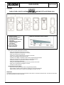
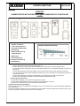
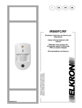
RIVELATORE A DOPPIO INFRAROSSO CON FUNZIONE PET DA ESTERNO CON
FOTOCAMERA
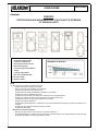
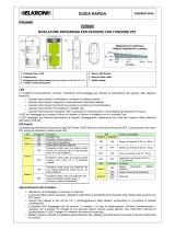
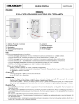
1. Tettuccio parasole
2. Obiettivo della fotocamera
3. Lenti dei sensori IR
4. LED rosso/Pulsante di funzione
5. Illuminatore
6. Coperchio del vano batteria
7. Interruttore Tamper
8. Vano batteria
9. Blocco dip-switch
10. Braccio della staffa
11. Staffa di rotazione
LED
Il LED rosso si accende nelle seguenti condizioni:
- Il LED rosso lampeggia una volta ogni 20 minuti:
Il rivelatore ha perso la connessione con la centrale.
- Il LED rosso si illumina per 30 secondi:
Il rivelatore è in fase di inizializzazione e presenta un’anomalia.
- Il LED rosso lampeggia velocemente due volte:
Il rivelatore si è collegato correttamente alla centrale a seguito dell’apprendimento.
- Il LED rosso si illumina per 2 secondi durante il normale funzionamento:
Il rivelatore ha rilevato un movimento e presenta un’anomalia.
- Il LED rosso lampeggia rapidamente:
Il rivelatore sta trasmettendo immagini alla centrale e presenta un’anomalia.
- Il LED rosso e l’illuminatore lampeggiano una volta:
Il rivelatore è stata ripristinato.
Utilizzo del pulsante di funzione:
- Premere una volta il pulsante per inviare un segnale di supervisione.
- Per ripristinare il rivelatore: tenere premuto il pulsante per 10 secondi. Rilasciare il
pulsante quando l’illuminatore e il LED rosso lampeggiano entrambi una volta.
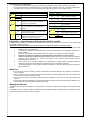
DIP Switch
La tabella seguente elenca la funzione di ogni DIP Switch. Il DIP Switch è in posizione ON oppure OFF. La posizione in alto indica
ON, mentre la posizione in basso indica OFF.
GUIDA RAPIDA
DS80TC1Q-002A
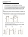
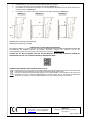
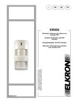
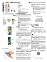
Grafico di rilevamento del rivelatore

DIP Posizione Funzione
Switch1 ON Disabilitazione tempo riposo
OFF Abilitazione tempo riposo (default)
Switch2 ON Riservato
OFF
Switch3
ON
Rivelatore rivolto verso uno spazio
chiuso (ad es. un muro più alto di una
persona entro 10 m dal rivelatore)
OFF
Rivelatore rivolto verso uno spazio
aperto (nessun muro entro 10 m dal
rivelatore) (default)
Switch4
ON
Rivelatore rivolto verso una superficie
che non rilascia facilmente calore (ad
es. un prato) (default)
OFF
Rivelatore rivolto verso una superficie
che rilascia facilmente calore (ad es.
in cemento, o pietra o piastrellata)
DIP Livello di sensibilità
Switch5 Switch6
ON ON Basso; per animali di 75 cm / 60
kg
ON OFF Medio; per animali di 60 cm / 40
kg
OFF ON Alto; per animali di 45 cm / 30 kg
OFF OFF Massimo; per animali di 30 cm /
20 kg (default)
DIP Posizione Funzione
Switch7 ON Doppio rilevamento abilitato
(default)
OFF Doppio rilevamento disabilitato
Switch8 ON Riservato
OFF
Apprendimento del rivelatore
Il rivelatore deve essere appreso dalla centrale per trasmettere il segnale qualora venga rilevato un movimento. Per far apprendere
il dispositivo, procedere come indicato di seguito.
Il rivelatore può essere appreso dalla centrale solo entro 3 minuti dall'accensione.
Togliere le viti di fissaggio del parasole per rimuovere tale componente.
Rimuovere il coperchio del vano batteria per accedere al vano batteria e ai Dip Switch.
Se necessario, configurare i Dip Switch; per le informazioni sull'impostazione, consultare la tabella fornita in
precedenza.
Inserire le due batterie al litio “AA” L91 nel vano batterie facendo attenzione a rispettare le polarità.
Accertarsi che l'interruttore Tamper sia aperto (sbloccato) prima di procedere alla fase successiva.
Entro 3 minuti dall'accensione, tenere premuto il pulsante di funzione per 10 secondi, quindi rilasciarlo
quando sia il LED rosso che l’Illuminatore lampeggiano una volta. Accertarsi di avere abilitato la funzione di
apprendimento sulla centrale.
Dopo essere stato appreso dalla centrale, il rivelatore verrà automaticamente registrato nel sistema.
Controllare la centrale per verificare che l’apprendimento e la registrazione siano avvenuti correttamente.
Una volta appreso dalla centrale, se il rivelatore perde la connessione, il LED lampeggerà per 20 minuti per
segnalare l’anomalia.
Modalità Walk Test
La modalità Test consente di controllare la copertura di rilevamento del dispositivo, non la portata di comunicazione con la centrale.
Per accedere alla modalità Test, tenere premuto il pulsante di funzione per alcuni secondi, quindi rilasciarlo per avviare la modalità
Test che dura per 3 minuti.
Durante i primi 30 secondi, il rivelatore esegue l’inizializzazione. Non generare allarmi durante tale periodo.
Al termine del periodo di inizializzazione, è possibile verificare la rilevazione di movimento davanti al rivelatore. Il LED rosso si
illumina per 2 secondi quando avviene la rivelazione.
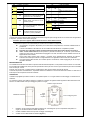
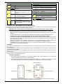
Installazione
Il rivelatore è progettato per essere montato su una superficie piana o in un angolo tramite le viti di fissaggio e i tasselli forniti in
dotazione.
La confezione contiene una staffa di rotazione in metallo per consentire la regolazione dell'angolazione della fotocamera e del
sensore. La staffa è dotata di fori per il fissaggio a parete o in angolo.
1. Utilizzare i fori di montaggio sulla staffa di rotazione per contrassegnare i punti corrispondenti sulla parete o in
angolo; se necessario inserire i tasselli nella parete.
2. Avvitare la staffa di rotazione nei punti di montaggio contrassegnati.
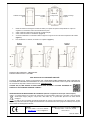
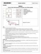
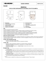
3. Avvitare il braccio della staffa sul rivelatore (Figura 1).
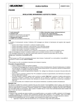
Installazione fotocamera
Fori di
montaggio
angolare
Selezione angolo fotocamera
Fori di montaggio angolare
Fori di
montaggio a
parete

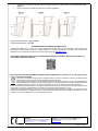
4. Agganciare il rivelatore sulla staffa di rotazione e regolare l'angolazione del rivelatore con i fori superiori della staffa
(Figura 2).
5. Fissare il rivelatore sulla staffa stringendo la vite superiore (Figura 3).
Figura 1 Figura 2 Figura 3
Frequenza radio di utilizzo: 2,405-2,475 GHz
Potenza radio trasmessa: 17,24 dBm
DICHIARAZIONE DI CONFORMITÀ UE SEMPLIFICATA
Il fabbricante, URMET S.p.A., dichiara che il tipo di apparecchiatura radio: RIVELATORE A DOPPIO INFRAROSSO CON
FUNZIONE PET DA ESTERNO CON FOTOCAMERA EIR600FC è conforme alla direttiva 2014/53/UE. Il testo completo della
dichiarazione di conformità UE è disponibile al seguente indirizzo Internet: www.elkron.com.
CLICCARE SUL SEGUENTE LINK DEL SITO ELKRON PER ACCEDERE ALLA SCHEDA TECNICA DEL PRODOTTO E
SCARICARE IL MANUALE COMPLETO
DIRETTIVA 2012/19/UE DEL PARLAMENTO EUROPEO E DEL CONSIGLIO del 4 luglio 2012 sui rifiuti di apparecchiature
elettriche ed elettroniche (RAEE).
Il simbolo del cassonetto barrato riportato sull’apparecchiatura o sulla sua confezione indica che il prodotto alla fine
della propria vita utile deve essere raccolto separatamente dagli altri rifiuti.
L’utente dovrà, pertanto, conferire l’apparecchiatura giunta a fine vita agli idonei centri comunali di raccolta differenziata
dei rifiuti elettrotecnici ed elettronici. In alternativa alla gestione autonoma è possibile consegnare l’apparecchiatura che
si desidera smaltire al rivenditore, al momento dell’acquisto di una nuova apparecchiatura di tipo equivalente.
Presso i rivenditori di prodotti elettronici con superficie di vendita di almeno 400 m2 è inoltre possibile consegnare gratuitamente,
senza obbligo di acquisto, i prodotti elettronici da smaltire con dimensione massima inferiore a 25 cm.
L’adeguata raccolta differenziata per l’avvio successivo dell’apparecchiatura dismessa al riciclaggio, al trattamento e allo
smaltimento ambientalmente compatibile contribuisce ad evitare possibili effetti negativi sull’ambiente e sulla salute e favorisce il
reimpiego e/o riciclo dei materiali di cui è composta l’apparecchiatura.
ELKRON
Tel. +39 011.3986711 - Fax +39 011.3986703
www.elkron.com – mail to: info@elkron.it
ELKRON è un marchio commerciale di URMET S.p.A.
Via Bologna 188/C – 10154 Torino (TO) Italia
HUwww.urmet.comUH
MADE IN TAIWAN

DIP Position Function
Switch1 ON Disable rest time
OFF Enable rest time (default)
Switch2 ON Reserved
OFF
Switch3
ON
Detector facing a closed space (eg a wall
higher than a person within 10 m of the
detector)
OFF Detector facing an open space (no wall
within 10 m of the detector) (default)
Switch4
ON Detector facing a surface that does not
easily release heat (eg a lawn) (default)
OFF
Detector facing a surface that easily
releases heat (eg in cement, or stone or
tiled)
ENGLISH
EIR600FC
PET IMMUNE OUTDOOR DOUBLE INFRARED DETECTOR WITH CAMERA
1. Sun shield
2. Camera lens
3. IR sensor lenses
4. Red LED/Function button
5. Illuminator
6. Battery compartment cover
7. Tamper switch
8. Battery compartment
9. Dip switch block
10. Bracket arm
11. Rotation bracket
LED
The red LED lights up in the following conditions:
- The red LED flashes once every 20 minutes: The detector has lost its connection with the control unit.
- The red LED lights up for 30 seconds: The detector is being initialised and a fault was detected.
- The red LED flashes quickly twice: The detector is connected correctly to the control unit after the learning procedure.
- The red LED lights up for two seconds during normal operation: The detector has detected motion and a fault was
detected.
- The red LED flashes quickly: The detector is transmitting images to the control unit and a fault was detected.
- The red LED and illuminator flash once: The detector was restored.
Using the function button:
Press the button once to send a supervision signal. To reset the detector: hold the button pressed for 10 seconds. Release the
button when the illuminator and the red LED blink once.
DIP Switch position table
Position the dip switches according to the place of installation of the detector and the pet immunity requirements.
The function of each dip switch is listed in the following table. The dip switches can be ON or OFF. Position up indicates
ON, position down indicates OFF.
QUICK GUIDE
DS80TC1Q-002A
DIP Sensitivity level
Switch5 Switch6
ON ON Low; for 75 cm / 60 kg animals
ON OFF Medium; for 60 cm / 40 kg animals
OFF ON High; for 45 cm / 30 kg animals
OFF OFF Maximum: for 30 cm/20 kg
animals (default)
DIP Position Function
Switch7
ON Enable double detection (default)
OFF Disable double detection
Switch8 ON Reserved
OFF
Detection chart

Learning of the detector by the control unit
The detector must be learnt by the control unit to transmit the signal if motion is detected. Proceed as follows to perform the
device learning procedure.
The detector may be learnt by the control unit only within three minutes from switch-on.
1. Remove the sun visor fastening screws to remove this component.
2. Remove the battery compartment cover to open the battery compartment and the dip switches.
3. If necessary, configure the dip switches; for information on setting, see the table provided above.
4. Insert the two lithium batteries “AA” L91 in the battery compartment, taking care to observe the polarity.
5. Make sure that the Tamper switch is open (released) before proceeding to the next step.
6. Within three minutes from switch-on, hold the function button pressed for 10 seconds and then release it when the red
LED and the illuminator blink once. Make sure that the learn function has been activated on the control unit.
7. After having been leant by the control unit, the detector is automatically recorded in the system. Check the control unit
to check that the learning and registration procedure were performed correctly.
8. Once learnt by the control unit, if the detector connection is lost, the LED will blink for 20 minutes to signal the fault.
Test mode
The Test mode is used to control the detection coverage of the device not the communication range with the control unit.
To access test mode, hold the function button pressed for a few seconds then release it to start the test mode that lasts for three
minutes.
The detector will start initialisation during the first 30 seconds. It is advisable not to generate alarms during this time.
Motion detection in front of the detector can be checked at the end of the initialisation period. The red LED lights up for two
seconds after detection.
Mounting and installation method
The detector was designed to be mounted on a flat surface or in a corner by means of the fixing screws and the anchor bolts
provided.
The package contains a metal rotation bracket to allow adjusting the camera and sensor angle. The bracket is
provided with holes for fixing to a wall or in a corner.
1. Use the installation holes on the rotation bracket to mark the corresponding points on the wall or in a corner; if
necessary, insert the anchor bolts into the wall.
2. Screw the rotation bracket in the marked installation points.
3. Screw the bracket arm onto the detector (Figure 1).
4. Clip on the detector onto the rotation bracket and adjust the detector angle with the upper holes of the bracket
(Figure 2).
5. Fix the detector onto the bracket by tightening the upper screw (Figure 3).
Figure 1 Figure 2 Figure 3
Camera
installation
Corner installation
holes
Camera angle selection
Corner installation holes
Installation
holes in wall

Radio frequency of use: 2,405-2,475 GHz
Radio power transmitted: 17,24 dBm
SIMPLIFIED EU DECLARATION OF CONFORMITY
Hereby, URMET S.p.A. declares that the radio equipment type: PET IMMUNE OUTDOOR DOUBLE INFRARED DETECTOR
WITH CAMERA EIR600FC is in compliance with Directive 2014/53/EU. The full text of the EU declaration of conformity is available
at the following internet address: www.elkron.com.
CLICK ON THE FOLLOWING LINK OF THE ELKRON SITE TO ACCESS THE PRODUCT TECHNICAL SHEET AND
DOWNLOAD THE COMPLETE MANUAL:
DIRECTIVE 2012/19/EU OF THE EUROPEAN PARLIAMENT AND OF THE COUNCIL of 4 July 2012 on waste electrical and
electronic equipment (WEEE).
The symbol of the crossed-out wheeled bin on the product or on its packaging indicates that this product must not be
disposed of with your other household waste.
Instead, it is your responsibility to dispose of your waste equipment by handing it over to a designated collection point
for the recycling of waste electrical and electronic equipment. The separate collection and recycling of your waste equipment at
the time of disposal will help to conserve natural resources and ensure that it is recycled in a manner that protects human health
and the environment.
For more information about where you can drop off your waste equipment for recycling, please contact your local city office,
your household waste disposal service or the shop where you purchased the product.
ELKRON
Tel. +39 011.3986711 - Fax +39
011.3986703
www.elkron.com – mail to: info@elkron.it
ELKRON is a trademark of URMET S.p.A.
Via Bologna 188/C – 10154 Turin (TO) Italy
www.urmet.com
MADE IN TAIWAN

FRANÇAIS
EIR600FC
DÉTECTEUR DOUBLE INFRAROUGE AVEC FONCTION PET D’EXTÉRIEUR
ET APPAREIL PHOTO
1. Visière pare-soleil
2. Objectif de l’appareil photo
3. Lentilles des capteurs IR
4. LED rouge/Touche de fonction
5. Dispositif d’éclairage
6. Cache du logement des batteries
7. Tamper
8. Logement des batteries
9. Bloc des commutateurs DIP
10. Bras de la bride
11. Bride de rotation
LED
La LED rouge s’allume dans les conditions suivantes :
- La LED rouge clignote toutes les 20 minutes :
Perte de connexion entre le détecteur et la centrale.
- La LED rouge s’allume pendant 30 secondes :
Le détecteur est en phase d’initialisation et il présente une anomalie.
- La LED rouge clignote rapidement deux fois :
Le détecteur s’est connecté correctement à la centrale à la suite de l’apprentissage.
- La LED rouge s’allume pendant 2 secondes pendant le fonctionnement normal :
Le détecteur a capté un mouvement et il présente une anomalie.
- La LED rouge clignote rapidement :
La LED bleue clignote rapidement : le détecteur est en train de transmettre des images à la centrale et il présente une
anomalie.
- La LED rouge et le dispositif d’éclairage clignotent une fois :
Le détecteur a été rétabli.
Utilisation de la touche de fonction :
- Appuyer une fois sur la touche pour envoyer un signal de supervision.
- Pour rétablir le détecteur : maintenir la touche de fonction enfoncée pendant 10 secondes. Relâcher la touche dès que
le dispositif d’éclairage et la LED rouge clignotent une fois.
GUIDE RAPIDE
DS80TC1Q-002A
Graphique de détection

Table des positions des DIP Switch
Positionner les commutateurs DIP en fonction de l'endroit d’installation et des critères d’immunité aux animaux.
Les fonctions de chaque commutateur DIP sont énumérées dans le tableau suivant. Les commutateurs DIP peuvent
être ON ou OFF. La position en haut correspond à ON, tandis que la position en bas correspond à OFF.
Préparation – Apprentissage du détecteur par l’unité de contrôle
Le détecteur doit être appris par la centrale pour transmettre le signal en cas de détection d’un mouvement. Pour l’apprentissage
du dispositif, procéder comme suit :
Le détecteur ne peut être appris par la centrale que dans les 3 minutes qui suivent sa mise sous tension.
1. Retirer les vis de fixation pour déposer la visière pare-soleil. Retirer le cache pour accéder au logement des
batteries et aux commutateurs DIP.
2. Si nécessaire, configurer les commutateurs DIP ; pour plus d’informations sur la configuration, se reporter au
tableau ci-dessus.
3. Placer les deux batteries au lithium “AA” L91 dans leur logement, en veillant à respecter les polarités.
4. S’assurer que l’interrupteur tamper est ouvert (débloqué) avant de passer à la phase suivante.
5. Dans les 3 minutes qui suivent la mise hors tension, maintenir la touche de fonction enfoncée pendant 10
secondes, puis la relâcher dès que la LED rouge clignote une fois. S'assurer d'avoir habilité la fonction
d’apprentissage sur la centrale.
6. Une fois appris par la centrale, le détecteur est automatiquement enregistré dans le système. Contrôler la
centrale pour vérifier que l’apprentissage et l’enregistrement se sont déroulés correctement.
7. Après l’apprentissage, en cas de perte de connexion du détecteur, la LED clignotera toutes les 20 minutes pour
signaler l’anomalie.
Mode Test
Le mode Test permet de contrôler la couverture de détection du dispositif (différente de la portée de communication
avec la centrale).
Pour accéder au mode Test, maintenir la touche de fonction enfoncée pendant quelques secondes, puis la relâcher pour
lancer le mode Test, d’une durée de 3 minutes.
Au cours des 30 premières secondes, le détecteur effectue l’initialisation. Aucune alarme n'est émise pendant cette
période.
Au terme de la période d’initialisation, il sera possible de vérifier la détection des mouvements devant le détecteur. Lors
de la détection, la LED rouge s’allumera pendant 2 secondes.
Montage du détecteur
Le détecteur est conçu pour être installé sur une surface plane ou angulaire, à l’aide des vis de fixation et des chevilles livrées
de série.
L’emballage contient une bride de rotation en métal permettant le réglage de l’angle de l'appareil photo et du capteur. La bride
est dotée d’orifices pour la fixation murale ou angulaire.
DIP Position Fonction
Switch1 ON Désactivation temps de repos
OFF Habilitation temps de repos (par défaut)
Switch2 ON Réservé
OFF
Switch3
ON
Détecteur faisant face à un espace clos (par
exemple un mur plus haut qu'une personne à
moins de 10 m du détecteur)
OFF
Détecteur faisant face à un espace ouvert (pas
de mur à moins de 10 m du détecteur) (par
défaut)
Switch4
ON
Détecteur faisant face à une surface qui ne
dégage pas facilement de chaleur (par exemple
une pelouse) (par défaut)
OFF
Détecteur faisant face à une surface qui libère
facilement de la chaleur (dans le ciment, la
pierre ou le carrelage, par exemple)
DIP Niveau de sensibilité
Switch5 Switch6
ON ON Bas : animal de 75 cm/60 kg
ON OFF Moyen : animal de 60 cm/40 kg
OFF ON Haut : animal de 45 cm/30 kg
OFF OFF Maximum : animal de 30 cm/20
kg ( par défaut )
DIP Position Fonction
Switch7
ON Habilitation double détection (par
défaut)
OFF Désactivation double détection
Switch8 ON Réservé
OFF

1. Utiliser les orifices de montage sur la bride de rotation pour repérer les points correspondants sur la paroi ou
angulaires ; si nécessaire, insérer des chevilles dans la paroi.
2. Visser la bride de rotation dans les points de montage indiqués.
3. Visser le bras de la bride sur le détecteur (Figure 1).
4. Accrocher le détecteur sur la bride de rotation et régler son angle en fonction des orifices supérieures de la bride
(Figure 2).
5. Fixer le détecteur sur la bride, en serrant la vis supérieure (Figure 3).
Figure 1 Figure 2 Figure 3
Fréquence radio d'utilisation : 2,405-2,475 GHz
Puissance radio transmise : 17,24 dBm
DECLARATION UE DE CONFORMITÉ SIMPLIFIÉE
Le fabricant, URMET S.p.A., déclare que l’équipement radio : DÉTECTEUR DOUBLE INFRAROUGE AVEC FONCTION PET
D’EXTÉRIEUR ET APPAREIL PHOTO EIR600FC est conforme à la directive 2014/53/UE. Le texte complet de la déclaration UE
de conformité est disponible à l’adresse internet suivant : www.elkron.com.
CLIQUEZ SUR LE LIEN SUIVANT DU SITE ELKRON POUR ACCÉDER À LA FICHE TECHNIQUE DU
PRODUIT ET TÉLÉCHARGER LE MANUEL COMPLET :
LES BONS GESTES DE MISE AU REBUT DE CE PRODUIT (Déchets d’équipements électriques et électroniques)
Ce symbole apposé sur le produit, ses accessoires ou sa documentation indique que ni le produit, ni ses accessoires
électroniques usagés (chargeur, casque audio, câble USB, etc.), ne peuvent être jetés avec les autres déchets
ménagers.
La mise au rebut incontrôlée des déchets présentant des risques environnementaux et de santé publique, veuillez
séparer vos produits et accessoires usagés des autres déchets. Vous favoriserez ainsi le recyclage de la matière qui les compose
dans le cadre d’un développement durable.
ELKRON
Tel. +39 011.3986711 - Fax +39 011.3986703
www.elkron.com – mail to: info@elkron.it
ELKRON est une marque commerciale de URMET S.p.A.
Via Bologna 188/C – 10154 Turin (TO) Italie
www.urmet.com
MADE IN TAIWAN
Installation de l’appareil
photo
Orifices de montage
angulaire
Sélection de l’angle de l’appareil photo
Orifices de montage
angulaire
Orifices de
montage mural

DEUTSCH
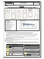
EIR600FC
AUßENDETEKTOR MIT DOPPELTEM INFRAROTSENSOR MIT PET-FUNKTION MIT
KAMERA
1. Sonnenblende
2. Objektiv der Kamera
3. Linsen der IR-Sensoren
4. Rote LED / Funktionstaste
5. Beleuchtung
6. Batteriefachabdeckung
7. Tamper-Schalter
8. Batteriefach
9. Dip-Schalter-Block
10. Ausleger der Halterung
11. Drehhalterung
LED
- Die rote LED leuchtet unter den folgenden Bedingungen auf:
- Die rote LED blinkt einmal alle 20 minuten: Der Detektor hat die Verbindung mit dem Steuergerät verloren.
- Die rote LED leuchtet 30 Sekunden lang auf: Der Detektor befindet sich in der Initialisierungsphase und weist eine
Störung auf.
- Die rote LED blinkt zweimal schnell: Der Detektor ist nach dem Einlernen korrekt mit dem Steuergerät verbunden.
- Die rote LED leuchtet während des Normalbetriebs 2 Sekunden lang auf: Der Detektor hat eine Bewegung erfasst und
weist eine Störung auf.
- Die rote LED blinkt schnell: Der Detektor überträgt Bilder an das Steuergerät und weist eine Störung auf.
- Die rote LED und die Beleuchtung blinken einmal: Der Detektor arbeitet wieder korrekt.
Verwendung der Funktionstaste:
- Die Taste einmal betätigen, um ein Überwachungssignal zu versenden.
- Zur Zurücksetzung des Detektors: die Taste 10 Minuten lang gedrückt halten. Die Taste
loslassen, wenn die Beleuchtung und die rote LED beide einmal blinken.
Tabelle der Positionen der DIP-Switches
Die Dip-Schalter abhängig vom Installationsort des Detektors und von den Anforderungen an die Unempfindlichkeit gegenüber
Tieren positionieren.
Die Funktion jedes Dip-Schalters ist in der nachstehenden Tabelle aufgeführt. Die Dip-Schalter können ON oder OFF sein. Die
Position oben gibt ON an, während die Position unten OFF entspricht.
SCHNELLANLEITUNG
DS80TC1Q-002A
Graph der Detektorerfassung

Vorbereitung - Einlernen des Detektors von Seiten des Steuergeräts
Der Detektor muss vom Steuergerät eingelernt werden, um das Signal zu übertragen, wenn eine Bewegung erfasst wird. Zum
Einlernen der Vorrichtung wie im Anschluss beschrieben vorgehen.
Der Detektor kann vom Steuergerät nur innerhalb von 3 Minuten ab seinem Einschalten eingelernt werden.
- Die Befestigungsschrauben der Sonnenblende entfernen, um dieses Bauteil zu entfernen.
- Die Batteriefachabdeckung abnehmen, um Zugang zum Batteriefach und zu den Dip-Schaltern zu erhalten.
- Wenn erforderlich die Dip-Schalter konfigurieren. Wegen Informationen zur Einstellung die zuvor erteilte Tabelle
einsehen.
- Die beiden Lithium-Batterien Format "AA" L91 in das Batteriefach einlegen und dabei die Polaritäten beachten.
- Vergewissern Sie sich vor dem nächsten Schritt, dass der Tamper-Schalter geöffnet ist (gelöst).
- Innerhalb von 3 Minuten nach dem Einschalten die Funktionstaste 10 Sekunden gedrückt halten, dann loslassen,
wenn sowohl die rote LED als auch die Beleuchtung einmal blinken. Sicherstellen, dass auf dem Steuergerät die
Einlernfunktion aktiviert wurde.
- Nachdem der Detektor in das Steuergerät eingelernt wurde, wird dieser automatisch im System registriert. Das
Steuergerät kontrollieren, um zu überprüfen, ob das Einlernen und die Registrierung korrekt erfolgt sind.
- Sobald der Detektor in das Steuergerät eingelernt wurde, blinkt die LED, sollte der Detektor die Verbindung verlieren,
20 Minuten lang, um die Störung anzuzeigen.
Test-Modus
Der Test-Modus gestattet die Kontrolle der Erfassungsreichweite der Vorrichtung doch nicht der Kommunikationsreichweite mit
dem Steuergerät.
Um in den Test-Modus zu gelangen, die Funktionstaste einige Sekunden lang betätigen und dann loslassen, um den Test-Modus
zu starten, der 3 Minuten dauert.
Während der ersten 30 Sekunden führt der Detektor die Initialisierung durch. Während dieses Zeitraums dürfen keine Alarme
generiert werden.
Nach dem Initialisierungszeitraum kann die Bewegungserfassung vor dem Detektor überprüft werden. Die rote LED leuchtet 2
Sekunden lang auf, wenn die Erfassung erfolgt.
Montage des Detektors
Der Detektor wurde für die Montage auf einer ebenen Oberfläche oder in einem Winkel mit den im Lieferumfang
enthaltenen Befestigungsschrauben und Dübeln ausgelegt.
Die Verpackung enthält eine Drehhalterung aus Metall zur Einstellung der Winkelposition der Kamera und des
Sensors. Die Halterung ist mit Öffnungen zur Befestigung an der Wand oder in einer Ecke ausgestattet.
1. Die Montagebohrungen auf der Drehhalterung verwenden, um die entsprechenden Punkte auf der Wand oder im
Winkel zu kennzeichnen. Wenn erforderlich, die Dübel in die Wand einsetzen.
DIP Position Funktion
Switch1 ON Deaktivierung Ruhezeit
OFF Aktivierung Ruhezeit (Standard)
Switch2 ON Reserviert
OFF
Switch3
ON
Detektor, der auf einen geschlossenen
Raum gerichtet ist (z. B. eine Wand höher
als eine Person innerhalb von 10 m vom
Detektor)
OFF
Detektor, der auf einen offenen Raum
gerichtet ist (keine Wand innerhalb von 10
m vom Detektor) (Standard)
Switch4
ON
Detektor, der auf eine Oberfläche gerichtet
ist, die nicht leicht Wärme abgibt (z. B.
Rasen) (Standard)
OFF
Detektor, der auf eine Oberfläche gerichtet
ist, die leicht Wärme abgibt (z. B. in Zement,
Stein oder Fliesen)
DIP Empfindlichkeitsstufe
Switc
h5
Switch6
ON ON Niedrig: für Tiere mit 75 cm/60 kg
ON OFF Mittel: für Tiere mit 60 cm/40 kg
OFF ON Hoch: für Tiere mit 45 cm/30 kg
OFF OFF Maximal
:
Tier mit
30 cm/20 kg
(Standard)
DIP Position Funktion
Switc
h7
ON Aktivierung Doppelerfassung (Standard)
OFF Deaktivierung Doppelerfassung
Switc
h8
ON Reserviert
OFF
Kamerainstallation
Winkelmontageb
ohrungen
Auswahl Kamerawinkel
Winkelmontagebohrungen
Wandmontageb
ohrungen

2. Die Drehhalterung in den gekennzeichneten Montagepunkten verschrauben.
3. Den Ausleger der Halterung auf dem Detektor verschrauben (Abbildung 1).
4. Den Detektor auf der Drehhalterung befestigen und die Winkelposition des Detektors über die oberen Öffnungen der
Halterung regulieren (Abbildung 2).
5. Den Detektor durch Anziehen der oberen Schraube an der Halterung befestigen (Abbildung 3).
Abbildung 1 Abbildung 2 Abbildung 3
Radiofrequenz der Nutzung: 2,405-2,475 GHz
Übertragene Funkleistung: 17,24 dBm
VEREINFACHTE EU-KONFORMITÄTSERKLÄRUNG
Der Hersteller, URMET S.p.A., erklärt, dass der Funkgerätetyp: AUßENDETEKTOR MIT DOPPELTEM INFRAROTSENSOR MIT
PET-FUNKTION MIT KAMERA EIR600FC der Richtlinie 2014/53/UE entspricht. Der ungekürzte Text der EU-
Konformitätserklärung steht unter der folgenden Internetadresse zur Verfügung: www.elkron.com
KLICKEN SIE AUF DEN FOLGENDEN LINK DER ELKRON-WEBSITE, UM AUF DAS TECHNISCHE DATENBLATT
ZUZUGREIFEN UND DAS VOLLSTÄNDIGE HANDBUCH HERUNTERZULADEN:
KORREKTE ENTSORGUNG VON ALTGERÄTEN (Elektroschrott)
Diese Kennzeichnung auf dem Produkt, den Zubehörteilen oder der Dokumentation weist darauf hin, dass das Produkt
und die elektronischen Zubehörteile nicht mit anderem Hausmüll entsorgt werden dürfen.
Entsorgen Sie dieses Gerät und Zubehörteile bitte getrennt von anderen Abfällen, um der Umwelt bzw. der menschlichen
Gesundheit nicht durch unkontrollierte Müllbeseitigung zu schaden. Helfen Sie mit, das Altgerät und Zubehörteile
fachgerecht zu entsorgen, um die nachhaltige Wiederverwertung von stofflichen Ressourcen zu fördern.
ELKRON
Tel. +39 011.3986711 - Fax +39 011.3986703
www.elkron.com – mail to: info@elkron.it
ELKRON ist ein eingetragenes Warenzeichen von
URMET S.p.A.
Via Bologna 188/C – 10154 Torino (TO) Italy
www.urmet.com
MADE IN TAIWAN
-
 1
1
-
 2
2
-
 3
3
-
 4
4
-
 5
5
-
 6
6
-
 7
7
-
 8
8
-
 9
9
-
 10
10
-
 11
11
-
 12
12


Elkron EIR600FC Guide de démarrage rapide
- Taper
- Guide de démarrage rapide
dans d''autres langues
- italiano: Elkron EIR600FC Guida Rapida
- English: Elkron EIR600FC Quick start guide
- Deutsch: Elkron EIR600FC Schnellstartanleitung
Documents connexes
-
 Elkron EIR600FC Guide d'installation
-
 Elkron EIR600 Guide de démarrage rapide
-
 Elkron EIR600 Guide d'installation
-
 Elkron IR600VC Guide de démarrage rapide
-
 Elkron IRT600 Guide de démarrage rapide
-
 Elkron IR600FC Guide de démarrage rapide
-
 Elkron DT610/BR Guide de démarrage rapide
-
 Elkron IR600FC/N Guide de démarrage rapide
-
 Elkron DT610/BR Guide d'installation
-
 Elkron IR600FC/RF Guide d'installation


