Lincoln Electric E-Cell Wire Drive System Mode d'emploi
- Catégorie
- Système de soudage
- Taper
- Mode d'emploi

E-CELL
®
WIRE DRIVE
Operator’s Manual
Save for future reference
Date Purchased
Code: (ex: 10859)
Serial: (ex: U1060512345)
IM876-A | Issue D ate 10-Mar
© Lincoln Global, Inc. All Rights Reserved.
For use with machines having Code Numbers:
11240, 11721
Register your machine:
www.lincolnelectric.com/register
Authorized Service and Distributor Locator:
www.lincolnelectric.com/locator

FOR ENGINE
powered equipment.
1.a. Turn the engine off before troubleshooting and maintenance
work unless the maintenance work requires it to be running.
____________________________________________________
1.b. Operate engines in open, well-ventilated
areas or vent the engine exhaust fumes
outdoors.
____________________________________________________
1.c. Do not add the fuel near an open flame
welding arc or when the engine is running.
Stop the engine and allow it to cool before
refueling to prevent spilled fuel from vaporiz-
ing on contact with hot engine parts and
igniting. Do not spill fuel when filling tank. If
fuel is spilled, wipe it up and do not start
engine until fumes have been eliminated.
____________________________________________________
1.d. Keep all equipment safety guards, covers and devices in
position and in good repair.Keep hands, hair, clothing and
tools away from V-belts, gears, fans and all other moving
parts when starting, operating or repairing equipment.
____________________________________________________
1.e. In some cases it may be necessary to remove safety
guards to perform required maintenance. Remove
guards only when necessary and replace them when the
maintenance requiring their removal is complete.
Always use the greatest care when working near moving
parts.
___________________________________________________
1.f. Do not put your hands near the engine fan.
Do not attempt to override the governor or
idler by pushing on the throttle control rods
while the engine is running.
___________________________________________________
1.g. To prevent accidentally starting gasoline engines while
turning the engine or welding generator during maintenance
work, disconnect the spark plug wires, distributor cap or
magneto wire as appropriate.
i
SAFETY
i
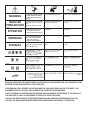
ARC WELDING CAN BE HAZARDOUS. PROTECT YOURSELF AND OTHERS FROM POSSIBLE SERIOUS INJURY OR DEATH.
KEEP CHILDREN AWAY. PACEMAKER WEARERS SHOULD CONSULT WITH THEIR DOCTOR BEFORE OPERATING.
Read and understand the following safety highlights. For additional safety information, it is strongly recommended that you
purchase a copy of “Safety in Welding & Cutting - ANSI Standard Z49.1” from the American Welding Society, P.O. Box
351040, Miami, Florida 33135 or CSA Standard W117.2-1974. A Free copy of “Arc Welding Safety” booklet E205 is available
from the Lincoln Electric Company, 22801 St. Clair Avenue, Cleveland, Ohio 44117-1199.
BE SURE THAT ALL INSTALLATION, OPERATION, MAINTENANCE AND REPAIR PROCEDURES ARE
PERFORMED ONLY BY QUALIFIED INDIVIDUALS.
WARNING
Mar ‘95
ELECTRIC AND
MAGNETIC FIELDS
may be dangerous
2.a. Electric current flowing through any conductor causes
localized Electric and Magnetic Fields (EMF). Welding
current creates EMF fields around welding cables and
welding machines
2.b. EMF fields may interfere with some pacemakers, and
welders having a pacemaker should consult their physician
before welding.
2.c. Exposure to EMF fields in welding may have other health
effects which are now not known.
2.d. All welders should use the following procedures in order to
minimize exposure to EMF fields from the welding circuit:
2.d.1.
Route the electrode and work cables together - Secure
them with tape when possible.
2.d.2. Never coil the electrode lead around your body.
2.d.3. Do not place your body between the electrode and
work cables. If the electrode cable is on your right
side, the work cable should also be on your right side.
2.d.4. Connect the work cable to the workpiece as close as
possible to the area being welded.
2.d.5. Do not work next to welding power source.
1.h. To avoid scalding, do not remove the
radiator pressure cap when the engine is
hot.
CALIFORNIA PROPOSITION 65 WARNINGS
Diesel engine exhaust and some of its constituents
are known to the State of California to cause can-
cer, birth defects, and other reproductive harm.
The engine exhaust from this product contains
chemicals known to the State of California to cause
cancer, birth defects, or other reproductive harm.
The Above For Diesel Engines
The Above For Gasoline Engines

ii
SAFETY
ii
ARC RAYS can burn.
4.a. Use a shield with the proper filter and cover
plates to protect your eyes from sparks and
the rays of the arc when welding or observing
open arc welding. Headshield and filter lens
should conform to ANSI Z87. I standards.
4.b. Use suitable clothing made from durable flame-resistant
material to protect your skin and that of your helpers from
the arc rays.
4.c. Protect other nearby personnel with suitable, non-flammable
screening and/or warn them not to watch the arc nor expose
themselves to the arc rays or to hot spatter or metal.
ELECTRIC SHOCK can
kill.
3.a. The electrode and work (or ground) circuits
are electrically “hot” when the welder is on.
Do not touch these “hot” parts with your bare
skin or wet clothing. Wear dry, hole-free
gloves to insulate hands.
3.b. Insulate yourself from work and ground using dry insulation.
Make certain the insulation is large enough to cover your full
area of physical contact with work and ground.
In addition to the normal safety precautions, if welding
must be performed under electrically hazardous
conditions (in damp locations or while wearing wet
clothing; on metal structures such as floors, gratings or
scaffolds; when in cramped positions such as sitting,
kneeling or lying, if there is a high risk of unavoidable or
accidental contact with the workpiece or ground) use
the following equipment:
• Semiautomatic DC Constant Voltage (Wire) Welder.
• DC Manual (Stick) Welder.
• AC Welder with Reduced Voltage Control.
3.c. In semiautomatic or automatic wire welding, the electrode,
electrode reel, welding head, nozzle or semiautomatic
welding gun are also electrically “hot”.
3.d. Always be sure the work cable makes a good electrical
connection with the metal being welded. The connection
should be as close as possible to the area being welded.
3.e. Ground the work or metal to be welded to a good electrical
(earth) ground.
3.f.
Maintain the electrode holder, work clamp, welding cable and
welding machine in good, safe operating condition. Replace
damaged insulation.
3.g. Never dip the electrode in water for cooling.
3.h. Never simultaneously touch electrically “hot” parts of
electrode holders connected to two welders because voltage
between the two can be the total of the open circuit voltage
of both welders.
3.i. When working above floor level, use a safety belt to protect
yourself from a fall should you get a shock.
3.j. Also see Items 6.c. and 8.
FUMES AND GASES
can be dangerous.
5.a. Welding may produce fumes and gases
hazardous to health. Avoid breathing these
fumes and gases. When welding, keep
your head out of the fume. Use enough
ventilation and/or exhaust at the arc to keep
fumes and gases away from the breathing zone. When
welding with electrodes which require special
ventilation such as stainless or hard facing (see
instructions on container or MSDS) or on lead or
cadmium plated steel and other metals or coatings
which produce highly toxic fumes, keep exposure as
low as possible and within applicable OSHA PEL and
ACGIH TLV limits using local exhaust or mechanical
ventilation. In confined spaces or in some circum-
stances, outdoors, a respirator may be required.
Additional precautions are also required when welding
on galvanized steel.
5. b. The operation of welding fume control equipment is affected
by various factors including proper use and positioning of
the equipment, maintenance of the equipment and the spe-
cific welding procedure and application involved. Worker
exposure level should be checked upon installation and
periodically thereafter to be certain it is within applicable
OSHA PEL and ACGIH TLV limits.
5.c.
Do not weld in locations near chlorinated hydrocarbon
vapors
coming from degreasing, cleaning or spraying operations.
The heat and rays of the arc can react with solvent vapors
to
form phosgene, a highly toxic gas, and other irritating prod-
ucts.
5.d. Shielding gases used for arc welding can displace air and
cause injury or death. Always use enough ventilation,
especially in confined areas, to insure breathing air is safe.
5.e. Read and understand the manufacturer’s instructions for this
equipment and the consumables to be used, including the
material safety data sheet (MSDS) and follow your
employer’s safety practices. MSDS forms are available from
your welding distributor or from the manufacturer.
5.f. Also see item 1.b.
Jan ‘09

iii
SAFETY
iii
FOR ELECTRICALLY
powered equipment.
8.a. Turn off input power using the disconnect
switch at the fuse box before working on
the equipment.
8.b. Install equipment in accordance with the U.S. National
Electrical Code, all local codes and the manufacturer’s
recommendations.
8.c. Ground the equipment in accordance with the U.S. National
Electrical Code and the manufacturer’s recommendations.
CYLINDER may explode
if damaged.
7.a. Use only compressed gas cylinders
containing the correct shielding gas for the
process used and properly operating
regulators designed for the gas and
pressure used. All hoses, fittings, etc. should be suitable for
the application and maintained in good condition.
7.b. Always keep cylinders in an upright position securely
chained to an undercarriage or fixed support.
7.c. Cylinders should be located:
• Away from areas where they may be struck or subjected to
physical damage.
• A safe distance from arc welding or cutting operations and
any other source of heat, sparks, or flame.
7.d. Never allow the electrode, electrode holder or any other
electrically “hot” parts to touch a cylinder.
7.e. Keep your head and face away from the cylinder valve outlet
when opening the cylinder valve.
7.f. Valve protection caps should always be in place and hand
tight except when the cylinder is in use or connected for
use.
7.g. Read and follow the instructions on compressed gas
cylinders, associated equipment, and CGA publication P-l,
“Precautions for Safe Handling of Compressed Gases in
Cylinders,” available from the Compressed Gas Association
1235 Jefferson Davis Highway, Arlington, VA 22202.
WELDING and CUTTING
SPARKS can
cause fire or explosion.
6.a.
Remove fire hazards from the welding area.
If this is not possible, cover them to prevent
the welding sparks from starting a fire.
Remember that welding sparks and hot
materials from welding can easily go through small cracks
and openings to adjacent areas. Avoid welding near
hydraulic lines. Have a fire extinguisher readily available.
6.b. Where compressed gases are to be used at the job site,
special precautions should be used to prevent hazardous
situations. Refer to “Safety in Welding and Cutting” (ANSI
Standard Z49.1) and the operating information for the
equipment being used.
6.c. When not welding, make certain no part of the electrode
circuit is touching the work or ground. Accidental contact
can cause overheating and create a fire hazard.
6.d. Do not heat, cut or weld tanks, drums or containers until the
proper steps have been taken to insure that such procedures
will not cause flammable or toxic vapors from substances
inside. They can cause an explosion even
though
they have
been “cleaned”. For information, purchase “Recommended
Safe Practices for the
Preparation
for Welding and Cutting of
Containers and Piping That Have Held Hazardous
Substances”, AWS F4.1 from the American Welding Society
(see address above).
6.e. Vent hollow castings or containers before heating, cutting or
welding. They may explode.
6.f.
Sparks and spatter are thrown from the welding arc. Wear oil
free protective garments such as leather gloves, heavy shirt,
cuffless trousers, high shoes and a cap over your hair. Wear
ear plugs when welding out of position or in confined places.
Always wear safety glasses with side shields when in a
welding area.
6.g. Connect the work cable to the work as close to the welding
area as practical. Work cables connected to the building
framework or other locations away from the welding area
increase the possibility of the welding current passing
through lifting chains, crane cables or other alternate cir-
cuits. This can create fire hazards or overheat lifting chains
or cables until they fail.
6.h. Also see item 1.c.
6.I. Read and follow NFPA 51B “ Standard for Fire Prevention
During Welding, Cutting and Other Hot Work”, available
from NFPA, 1 Batterymarch Park, PO box 9101, Quincy, Ma
022690-9101.
6.j. Do not use a welding power source for pipe thawing.
Jan ‘09
Refer to http://www.lincolnelectric.com/safety for additional safety information.

iv
SAFETY
iv
Mar. ‘93
PRÉCAUTIONS DE SÛRETÉ
Pour votre propre protection lire et observer toutes les instructions
et les précautions de sûreté specifiques qui parraissent dans ce
manuel aussi bien que les précautions de sûreté générales suiv-
antes:
Sûreté Pour Soudage A L’Arc
1. Protegez-vous contre la secousse électrique:
a. Les circuits à l’électrode et à la piéce sont sous tension
quand la machine à souder est en marche. Eviter toujours
tout contact entre les parties sous tension et la peau nue
ou les vétements mouillés. Porter des gants secs et sans
trous pour isoler les mains.
b. Faire trés attention de bien s’isoler de la masse quand on
soude dans des endroits humides, ou sur un plancher
metallique ou des grilles metalliques, principalement dans
les positions assis ou couché pour lesquelles une grande
partie du corps peut être en contact avec la masse.
c. Maintenir le porte-électrode, la pince de masse, le câble
de soudage et la machine à souder en bon et sûr état
defonctionnement.
d.Ne jamais plonger le porte-électrode dans l’eau pour le
refroidir.
e. Ne jamais toucher simultanément les parties sous tension
des porte-électrodes connectés à deux machines à souder
parce que la tension entre les deux pinces peut être le
total de la tension à vide des deux machines.
f. Si on utilise la machine à souder comme une source de
courant pour soudage semi-automatique, ces precautions
pour le porte-électrode s’applicuent aussi au pistolet de
soudage.
2. Dans le cas de travail au dessus du niveau du sol, se protéger
contre les chutes dans le cas ou on recoit un choc. Ne jamais
enrouler le câble-électrode autour de n’importe quelle partie
du corps.
3. Un coup d’arc peut être plus sévère qu’un coup de soliel,
donc:
a. Utiliser un bon masque avec un verre filtrant approprié
ainsi qu’un verre blanc afin de se protéger les yeux du ray-
onnement de l’arc et des projections quand on soude ou
quand on regarde l’arc.
b. Porter des vêtements convenables afin de protéger la
peau de soudeur et des aides contre le rayonnement de
l‘arc.
c. Protéger l’autre personnel travaillant à proximité au
soudage à l’aide d’écrans appropriés et non-inflammables.
4. Des gouttes de laitier en fusion sont émises de l’arc de
soudage. Se protéger avec des vêtements de protection libres
de l’huile, tels que les gants en cuir, chemise épaisse, pan-
talons sans revers, et chaussures montantes.
5. Toujours porter des lunettes de sécurité dans la zone de
soudage. Utiliser des lunettes avec écrans lateraux dans les
zones où l’on pique le laitier.
6. Eloigner les matériaux inflammables ou les recouvrir afin de
prévenir tout risque d’incendie dû aux étincelles.
7. Quand on ne soude pas, poser la pince à une endroit isolé de
la masse. Un court-circuit accidental peut provoquer un
échauffement et un risque d’incendie.
8. S’assurer que la masse est connectée le plus prés possible
de la zone de travail qu’il est pratique de le faire. Si on place
la masse sur la charpente de la construction ou d’autres
endroits éloignés de la zone de travail, on augmente le risque
de voir passer le courant de soudage par les chaines de lev-
age, câbles de grue, ou autres circuits. Cela peut provoquer
des risques d’incendie ou d’echauffement des chaines et des
câbles jusqu’à ce qu’ils se rompent.
9. Assurer une ventilation suffisante dans la zone de soudage.
Ceci est particuliérement important pour le soudage de tôles
galvanisées plombées, ou cadmiées ou tout autre métal qui
produit des fumeés toxiques.
10. Ne pas souder en présence de vapeurs de chlore provenant
d’opérations de dégraissage, nettoyage ou pistolage. La
chaleur ou les rayons de l’arc peuvent réagir avec les vapeurs
du solvant pour produire du phosgéne (gas fortement toxique)
ou autres produits irritants.
11. Pour obtenir de plus amples renseignements sur la sûreté,
voir le code “Code for safety in welding and cutting” CSA
Standard W 117.2-1974.
PRÉCAUTIONS DE SÛRETÉ POUR
LES MACHINES À SOUDER À
TRANSFORMATEUR ET À
REDRESSEUR
1. Relier à la terre le chassis du poste conformement au code de
l’électricité et aux recommendations du fabricant. Le dispositif
de montage ou la piece à souder doit être branché à une
bonne mise à la terre.
2. Autant que possible, I’installation et l’entretien du poste seront
effectués par un électricien qualifié.
3. Avant de faires des travaux à l’interieur de poste, la debranch-
er à l’interrupteur à la boite de fusibles.
4. Garder tous les couvercles et dispositifs de sûreté à leur
place.

vv
TThhaannkk YYoouu
for selecting a QUALITY product by Lincoln Electric. We want you
to take pride in operating this Lincoln Electric Company product
••• as much pride as we have in bringing this product to you!
Read this Operators Manual completely before attempting to use this equipment. Save this manual and keep it
handy for quick reference. Pay particular attention to the safety instructions we have provided for your protection.
The level of seriousness to be applied to each is explained below:
WARNING
This statement appears where the information must be followed exactly to avoid serious personal injury or loss of life.
This statement appears where the information must be followed to avoid minor personal injury or damage to this equipment.
CAUTION
Please Examine Carton and Equipment For Damage Immediately
When this equipment is shipped, title passes to the purchaser upon receipt by the carrier. Consequently, Claims
for material damaged in shipment must be made by the purchaser against the transportation company at the
time the shipment is received.
Please record your equipment identification information below for future reference. This information can be
found on your machine nameplate.
Product _________________________________________________________________________________
Model Number ___________________________________________________________________________
Code Number or Date Code_________________________________________________________________
Serial Number____________________________________________________________________________
Date Purchased___________________________________________________________________________
Where Purchased_________________________________________________________________________
Whenever you request replacement parts or information on this equipment, always supply the information you
have recorded above. The code number is especially important when identifying the correct replacement parts.
On-Line Product Registration
- Register your machine with Lincoln Electric either via fax or over the Internet.
• For faxing: Complete the form on the back of the warranty statement included in the literature packet
accompanying this machine and fax the form per the instructions printed on it.
• For On-Line Registration: Go to our
WEB SITE at www.lincolnelectric.com. Choose “Quick Links” and then
“Product Registration”. Please complete the form and submit your registration.
CUSTOMER ASSISTANCE POLICY
The business of The Lincoln Electric Company is manufacturing and selling high quality welding equipment, consumables, and cutting equip-
ment. Our challenge is to meet the needs of our customers and to exceed their expectations. On occasion, purchasers may ask Lincoln
Electric for advice or information about their use of our products. We respond to our customers based on the best information in our posses-
sion at that time. Lincoln Electric is not in a position to warrant or guarantee such advice, and assumes no liability, with respect to such infor-
mation or advice. We expressly disclaim any warranty of any kind, including any warranty of fitness for any customer’s particular purpose,
with respect to such information or advice. As a matter of practical consideration, we also cannot assume any responsibility for updating or
correcting any such information or advice once it has been given, nor does the provision of information or advice create, expand or alter any
warranty with respect to the sale of our products.
Lincoln Electric is a responsive manufacturer, but the selection and use of specific products sold by Lincoln Electric is solely within the control
of, and remains the sole responsibility of the customer. Many variables beyond the control of Lincoln Electric affect the results obtained in
applying these types of fabrication methods and service requirements.
Subject to Change – This information is accurate to the best of our knowledge at the time of printing. Please refer to www.lincolnelectric.com
for any updated information.

vi
vi
TABLE OF CONTENTS
Page
––––––––––––––––––––––––––––––––––––––––––––––––––––––––––––––––––––––––––––––––
Installation.......................................................................................................................Section A
Technical Specifications.......................................................................................................A-1
Wire Drive Features and Components .................................................................................A-2
Safety Precautions ...............................................................................................................A-3
Mounting and Unit Dimensions ............................................................................................A-3
Safety Precautions ...............................................................................................................A-4
Weld Cable Sizes ........................................................................................................................A-4
Coaxial Weld Cables ............................................................................................................A-5
External Shut Down Signal...................................................................................................A-6
Digitial Control Cable Connection ........................................................................................A-6
Setting Electrode Polarity .....................................................................................................A-7
Wire Drive Configuration ......................................................................................................A-8
Assembly of Drive Rolls and Wire Guides............................................................................A-9
Pressure Arm Adjustment ..................................................................................................A-10
Shielding Gas Connection..................................................................................................A-10
Wire Reel Loading..............................................................................................................A-11
________________________________________________________________________________
Operation.........................................................................................................................Section B
Safety Precautions ...............................................................................................................B-1
Graphic Symbols, Common Welding Abbreviations.............................................................B-1
Product Description, Recommended Processes and Required Equipment .........................B-2
Front And Rear Controls and Connections ..........................................................................B-3
1. Status LED ................................................................................................................B-4
2. Cold Feed / Gas Purge Switch..................................................................................B-4
3. 5-pin Amphenol .........................................................................................................B-4
________________________________________________________________________________
Accessories.....................................................................................................Section C
General Options / Accessories...............................................................C-1 Thru C-3
________________________________________________________________________
Maintenance ....................................................................................................Section D
Safety Precautions ................................................................................................D-1
Routine Maintenance.............................................................................................D-1
Periodic Maintenance............................................................................................D-1
Calibration Specification........................................................................................D-1
________________________________________________________________________
Troubleshooting............................................................................................................E
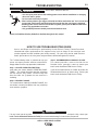
Safety Precautions.................................................................................................E-1
How To Use Troubleshooting Guide......................................................................E-1
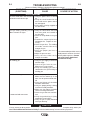
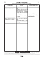
Troubleshooting .............................................................................................E-2, E-3
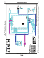
Wiring Diagram ......................................................................................................F-1
________________________________________________________________________
Parts Lists................................................................................................................P522
________________________________________________________________________

A-1
INSTALLATION
eCELL™ WIRE DRIVE SYSTEM
A-1
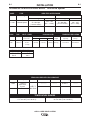
TECHNICAL SPECIFICATIONS
:
eCELL
™
Wire Drive System
CODE. TYPE WIRE FEED SPEED RANGE
ITEMS INCLUDED WITH EACH PRODUCT
Dimensions do not include wire reel.
CONTROL BOX, WIRE DRIVE AND COMPLETE UNITS
CODE TYPE
INPUT POWER
PHYSICAL SIZE• TEMPERATURE RATING
Input Voltage Dimensions
and Current Height Width Depth Weight Operating Storage
9.5“ 9.1“ 11.3“ 19 Lbs 14°F to 104°F -40°F to 185°F
11240
eCELL™ 40 VDC ( 241mm) ( 231mm) ( 287mm) (8.6 Kg.) -10°C to 40°C -40°C to 85°C
4 Amps
WELDING CAPACITY RATING
Amp Rating Duty Cycle
600 A 60%
500 A 100%
11240
CODE
11240
Gearing
Normal Speed
Description
eCELL™
Wire Drive
System
Wire Feeder
eCELL™
Wire Drive
WFS Range
50 – 800 ipm
(1.3-20.3 m/min.)
Wire Reel Stand
------------
WFS Range
50 – 800 ipm
(1.3-20.3 m/min.)
Drive Roll Kit
----------
Gun Bushing
K1500-1
Wire Sizes
.023 – .045
(0.6 – 1.2mm)
Wire Sizes
.030 - .045
(0.8 - 1.2mm)
Control Cable
---------
GMAW FCAW
TEMPERATURE RANGES
OPERATING TEMPERATURE RANGE
15°F to 104°F(-10°C to 40°C)
STORAGE TEMPERATURE RANGE
-40°F to 185°F(-40°C to 85°C)

eCELL™ WIRE DRIVE SYSTEM
A-2
INSTALLATION
A-2
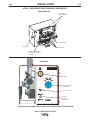
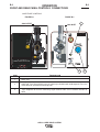
4 DRIVE ROLLS
S
PLIT WIRE GUIDE
ADJUSTABLE
PRESSURE ARMS
G
AS OUTLET
GUN RECEIVER BUSHING
FOR GUN AND CABLE
ASSEMBLY
DOOR REMOVED
SEE INSTALLATION AND OPERATION SECTIONS FOR DETAILED INFORMATION
eCELL™ WIRE DRIVE FEATURES AND COMPONENTS
GAS PURGEGAS PURGE
COLD FEEDCOLD FEED
G
AS INGAS IN
L12529-2 VM
TIGHTENTIGHTEN
LOOSENLOOSEN
U U
11
4
0 VDC40 VDC
I I
11
4A 4A
X
X
60% 60%
100%100%
II
2
2
600A 600A
500A500A
ÆÆ
STATUSSTATUS
ELECTRIC
LINCOLN
ARCLINK STATUS LED
ARCLINK CONNECTION
(5 PIN AMPHENOL)
COLD FEED
GAS PURGE
TOGGLE SWITCH
GAS INLET
REAR VIEW

A-3
INSTALLATION
eCELL™ WIRE DRIVE SYSTEM
A-3
SAFETY PRECAUTION
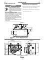
MOUNTING AND UNIT DIMENSIONS
Mount the eCell™ Wire Drive System on the designat-
ed bracket of the eCell™ only.
(See Figure A.1).
Side View (Door not shown for clarity). (See Figure A.2)
Rear View. (See Figure A.3)
ELECTRIC SHOCK can kill.
• Turn the input power OFF at the
welding power source before instal-
lation or changing drive rolls and/or
guides.
• Do not touch electrically live parts.
• When inching with the gun trigger, electrode
and drive mechanism are "hot" to work and
ground and could remain energized several
seconds after the gun trigger is released.
• Welding power source must be connected to
system ground per the National Electrical Code
or any applicable local codes.
• Only qualified personnel should perform main-
tenance work.
----------------------------------------------------------------------------------------
2.762.76
1.381.38
2.382.38
6.006.00
2.252.25
5/16 - 18 THREADS5/16 - 18 THREADS
(4 PLACES)(4 PLACES)
4.974.97
8.508.50
9.939.93
11.2511.25
4.974.97
1.391.39
8.828.82
5.085.08
8.508.50
FIGURE A.1
FIGURE A.2
FIGURE A.3
WARNING

A-4
INSTALLATION
eCELL™ WIRE DRIVE SYSTEM
A-4
SAFETY PRECAUTION
ELECTRIC SHOCK can kill.
• Only qualified personnel should
perform this installation.
• Turn off the input power to the
power source at the disconnect switch or fuse
box before working on this equipment. Turn off
the input power to any other equipment connect-
ed to the welding system at the disconnect
switch or fuse box before working on this equip-
ment.
• Do not touch electrically hot parts.
----------------------------------------------------------------------
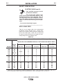
** Tabled values are for operation at ambient temperatures of 40°C (104°F) and below. Applications above 40°C
(104°F) may require cables larger than recommended, or cables rated higher than 75°C (167°F).
Amperes
200
200
225
225
250
250
250
250
300
325
350
400
400
500
Percent
Duty
Cycle
60
100
20
40 & 30
30
40
60
100
60
100
60
60
100
60
200 to 250 Ft.
61 to 76 m
1/0
1/0
1/0
1/0
1/0
1/0
1/0
1/0
2/0
3/0
3/0
4/0
4/0
4/0
150 to 200 Ft.
48 to 61 m
1
1
1
1
1
1
1
1
1/0
2/0
2/0
3/0
3/0
3/0
100 to 150 Ft.
31 to 48 m
2
2
2
2
2
1
1
1
1
2/0
2/0
2/0
3/0
3/0
50 to 100Ft.
15 to 31 m
2
2
3
3
3
2
1
1
1
2/0
1/0
2/0
3/0
2/0
0 to 50 Ft.
0 to 15 m
2
2
4 or 5
3
3
2
1
1
1
2/0
1/0
2/0
3/0
2/0
RECOMMENDED CABLE SIZES (RUBBER COVERED COPPER - RATED 75°C [167°F] )**
CABLE SIZES FOR COMBINED LENGTHS OF ELECTRODE AND WORK CABLES
WELD CABLE SIZES
Table A.1 has the copper cable sizes recommended
for different currents and duty cycles. Lengths stipu-
lated are the distance from the welder to work and
back to the welder again. Cable sizes are increased
for greater lengths primarily for the purpose of mini-
mizing voltage loss in the welding circuit.
TABLE A.1

A-5
INSTALLATION
eCELL™ WIRE DRIVE SYSTEM
A-5
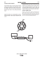
COAXIAL WELD CABLES
Coaxial welding cables are specially designed welding
cables for pulse welding. Coaxial weld cables feature
low inductance, allowing fast changes in the weld cur-
rent. Regular cables have a higher inductance which
may distort the pulse wave shape. Inductance
becomes more severe as the weld cables become
longer.
Coaxial weld cables are recommended for all pulse
welding, especially when the total weld cable length
(electrode cable + work cable) exceeds 50 feet
(7.6m).
A coaxial weld cable is constructed by 8 small leads
wrapped around one large lead. The large inner lead
connects to the electrode stud on the power source
and the electrode connection on the wire feeder. The
small leads combine together to form the work lead,
one end attached to the power source and the other
end to the work piece.
(See Coaxial weld Cable below.)
WORK CONNECTION
Connect a work lead of sufficient size between the
proper output stud on the power source and the work.
Be sure the connection to the work makes tight metal
to metal electrical contact. Poor work lead connec-
tions can result in poor welding performance.
Electrode
Work
Work
Power Source
Work
Electrode
Wire Feeder
Electrode
Work
Coaxial Weld Cable

A-6
INSTALLATION
eCELL™ WIRE DRIVE SYSTEM
A-6
EXTERNAL SHUTDOWN SIGNAL
ELECTRIC SHOCK can kill.
• Turn the input power OFF at the dis-
connect switch before working on
this equipment.
• Do not touch electrically hot parts.
• Only qualified personnel should install, use or
service this equipment.
------------------------------------------------------------------------
The eCell™ Wire Drive includes one input for an
external shut-off circuit. The circuit interrupts the trig-
ger signal and stops the welding process in the event
of a fault. The most common use is for a flow switch
when using water cooled guns or torches.
The external device must have "normally closed" con-
tacts.
Do not use the external shut-off circuits for safety or
emergency stops.
To connect to the shutoff circuit:
1. Turn off power to the wire feeder at the disconnect
switch.
2. Remove the screws securing the wrap-around and
door assembly.
3. Locate leads 570 and 570A/570B in the harness
for external shut-off switch. (See Figure A.4)
4. Wire the external equipment to the leads. Route
the wiring for the external equipment through the
rear of the wire feeder.
5. Reassemble the wrap-around and door assembly.
6. Restore power.
FIGURE A.4
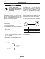
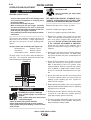
DIGITAL CONTROL CABLE, K1543-XX
ArcLink/LincNet control cables are special high quality
cables for digital communication. The cables are cop-
per 5 conductor cable in a SO-type rubber jacket.
There is one 20 gauge twisted pair for network com-
munications. This pair has an impedance of approxi-
mately 120 ohms and a propagation delay per foot of
less than 2.1 nanoseconds. There are two 12 gauge
conductors that are used to supply 40VDC to the net-
work. The fifth wire is 18 gauge and is used as an
electrode sense lead.
Use of non-standard cables may lead to system shut-
downs, poor arc starting and wire feeding problems.
The control cables connect the power source to the
wire feeder, and the wire feeder to other wire feeders.
PIN FUNCTION
A Digital I/O
B Digital I/O
C "67" voltage sense
D 40 VDC
E Common
Use a maximum of 250 feet (76.2m) of control cable
between components.
WARNING
EXTERNAL
DEVICE
570
570A/570B
E
D
C
B
A
E
D
C
B
A
P
OWER SOURCE
W
IRE FEEDER

A-7
INSTALLATION
eCELL™ WIRE DRIVE SYSTEM
A-7
SETTING ELECTRODE POLARITY
ELECTRIC SHOCK can kill.
• Turn the input power OFF at the dis-
connect switch before working on
this equipment.
• Do not touch electrically hot parts.
• Only qualified personnel should install, use or
service this equipment.
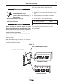
When changing the electrode polarity, the weld
cables must be changed at the power source
studs and the DIP switches inside the eCell™ Wire
Drive System must be properly set. Operation
with the DIP switch in the wrong position will
cause erratic arc performance.
------------------------------------------------------------------------
The eCell™ Wire Drive is factory set for Electrode
Positive welding.
Most GMAW welding procedures use Electrode
Positive welding. Some Innershield procedures may
use Electrode Negative welding.
To change the DIP switch inside the eCell™ Wire
Drive for electrode polarity: (See Figure A.5)
1. Turn off power at the welding power source.
2. Remove the sheet metal wrap-around on the wire
drive.
3. Locate DIP switches on the Wire Drive Board.
4. Set DIP switch #7 to the desired polarity.
DIP Switch #7 Position Polarity
ON - (negative) polarity
OFF + (positive) polarity
5. Assemble the wrap-around to the wire drive.
6. Restore power.
1 2 3 4 5 6 7 8
O
N
- (Negative) Polarity
LOCATION DIP SWITCH
1 2 3 4 5 6 7 8
O
N
+ (Positive) Polarity
eCELL WIRE DRIVE BOARD
FIGURE A.5
CAUTION
WARNING

6. Remove the outer wire guide, and push the gun
bushing out of the wire drive. Because of the pre-
cision fit, light tapping may be required to remove
the gun bushing.
7. Disconnect the shielding gas hose from the gun
bushing, if required.
8. Connect the shielding gas hose to the new gun
bushing, if required.
9. Rotate the gun bushing until the thumb screw hole
aligns with the thumb screw hole in the feed plate.
Slide the gun receiver bushing into the wire drive
and verify the thumb screw holes are aligned.
10. Tighten the socket head cap screw.
11. Insert the welding gun into the gun bushing and
tighten the thumb screw.
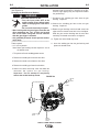
WIRE DRIVE CONFIGURATION
(See Figure A.6)
Changing the Gun Receiver Bushing
ELECTRIC SHOCK can kill.
• Turn the input power OFF at the
welding power source before instal-
lation or changing drive rolls and/or
guides.
• Do not touch electrically live parts.
• When inching with the gun trigger, electrode and
drive mechanism are "hot" to work and ground
and could remain energized several seconds
after the gun trigger is released.
• Only qualified personnel should perform mainte-
nance work.
------------------------------------------------------------------------
Tools required:
• 1/4" hex key wrench
Note: Some gun bushings do not require the use of
the thumb screw.
1. Turn power off at the welding power source.
2. Remove the welding wire from the wire drive.
3. Remove the thumb screw from the wire drive.
4. Remove the welding gun from the wire drive.
5. Loosen the socket head cap screw that holds the
connector bar against the gun bushing.
Important: Do not attempt to completely
remove the socket head cap screw.
A-8
INSTALLATION
eCELL™ WIRE DRIVE SYSTEM
A-8
WARNING
GUN RECEIVER BUSHING
CONNECTOR
BLOCK
SOCKET
HEAD CAP
SCREW
THUMB
SCREW
LOOSEN
CAP
SCREW
TIGHTEN
CAP
SCREW
FIGURE A.6

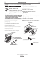
ASSEMBLY OF DRIVE ROLLS AND WIRE
GUIDES
ELECTRIC SHOCK can kill.
• Turn the input power OFF at the
welding power source before instal-
lation or changing drive rolls and/or
guides.
• Do not touch electrically live parts.
• When inching with the gun trigger, electrode
and drive mechanism are "hot" to work and
ground and could remain energized several sec-
onds after the gun trigger is released.
• Only qualified personnel should perform mainte-
nance work.
------------------------------------------------------------------------
To remove drive rolls and wire guides:
(See Figure A.7)
1. Turn power off at the welding power source.
2. Remove the outer wire guide.
3. Rotate 4 triangular rings to the unlocked position.
4. Open the pressure arms.
5. Remove the drive rolls and inner wire guide.
To install drive rolls and wire guides:
(See Figure A.7 and A.7a)
1. Turn off power at the welding power source.
2. Open pressure arms.
3. Assemble the inner wire guide.
4. Slide the drive rolls onto the drive hubs.
(See figure A.8)
5. Close the pressure arms.
6. Rotate 4 triangular rings to the locked position.
(See figure A.8a)
7. Assemble the outer wire guide.
8. Adjust the pressure arms to the recommended set-
ting.
WARNING
OUTER WIRE GUIDE
4 TRIANGULAR RINGS
IN UNLOCKED POSITION
2 PRESSURE ARMS
ROTATE DOWN
INNER WIRE GUIDE
DRIVE ROLLS
DRIVE HUBS
PRESSURE ARMS
IN OPEN POSITION
SLIDE DRIVE ROLL
ON DRIVE HUB
TRIANGULAR RING IN
UNLOCKED POSITION
TRIANGULAR RING IN
LOCKED POSITION
FIGURE A.7
FIGURE A.8
FIGURE A.8a
A-9
INSTALLATION
eCELL™ WIRE DRIVE SYSTEM
A-9

SHIELDING GAS CONNECTION
CYLINDER may explode if damaged.
• Keep cylinder upright and chained to
support.
• Keep cylinder away from areas where
it may be damaged.
• Never lift welder with cylinder attached.
• Never allow welding electrode to touch cylinder.
• Keep cylinder away from welding or other live elec-
trical circuits.
---------------------------------------------------------------------------
BUILD-UP OF SHIELDING GAS may
harm health or kill.
• Shut off shielding gas supply when
not in use.
SEE AMERICAN NATIONAL STANDARD Z-49.1,
"SAFETY IN WELDING AND CUTTING" PUB-
LISHED BY THE AMERICAN WELDING SOCIETY.
------------------------------------------------------------------------
Maximum inlet pressure is 100 psi. (6.9 bar.)
Install the shielding gas supply as follows:
1. Secure the cylinder to prevent it from falling.
2. Remove the cylinder cap. Inspect the cylinder
valves and regulator for damaged threads, dirt,
dust, oil or grease. Remove dust and dirt with a
clean cloth. DO NOT ATTACH THE REGULATOR
IF OIL, GREASE OR DAMAGE IS PRESENT!
Inform your gas supplier of this condition. Oil or
grease in the presence of high pressure oxygen is
explosive.
3. Stand to one side away from the outlet and open
the cylinder valve for an instant. This blows away
any dust or dirt which may have accumulated in the
valve outlet.
4. Attach the flow regulator to the cylinder valve and
tighten the union nut(s) securely with a wrench.
Note: if connecting to 100% CO
2
cylinder, insert
regulator adapter between regulator and cylinder
valve. If adapter is equipped with a plastic washer,
be sure it is seated for connection to the CO
2
cylin-
der.
5. Attach one end of the inlet hose to the outlet fitting
of the flow regulator. Attach the other end to the
welding system shielding gas inlet. Tighten the
union nuts with a wrench.
6. Before opening the cylinder valve, turn the regulator
adjusting knob counterclockwise until the adjusting
spring pressure is released.
7. Standing to one side, open the cylinder valve slowly
a fraction of a turn. When the cylinder pressure
gage stops moving, open the valve fully.
8. The flow regulator is adjustable. Adjust it to the flow
rate recommended for the procedure and process
being used before making a weld.
A-10
INSTALLATION
eCELL™ WIRE DRIVE SYSTEM
A-10
PRESSURE ARM ADJUSTMENT
ELECTRIC SHOCK can kill.
• Turn the input power OFF at the welding power
source before installation or changing drive
rolls and/or guides.
• Do not touch electrically live parts.
• When inching with the gun trigger, electrode
and drive mechanism are "hot" to work and
ground and could remain energized several sec-
onds after the gun trigger is released.
• Only qualified personnel should perform mainte-
nance work.
------------------------------------------------------------------------
The pressure arm controls the amount of force the
drive rolls exert on the wire. Proper adjustment of
both pressure arms gives the best welding perfor-
mance.
Set the pressure arm as follows (See Figure A.9):
Aluminum wires between 1 and 3
Cored wires between 3 and 4
Steel, Stainless wires between 4 and 6
For best results, use the same setting on both pres-
sure arms. This maximizes traction of the drive rolls
while minimizing wire deformation.
FIGURE A.9
WARNING
ALUMINU M
OUTERSHIELD
METAL SHIELD
INNERS HIELD
STEEL
STAINLE SS
CORED WIRES
SOLID WIRES
6
1
3
2
5
4
WARNING

WIRE REEL LOADING
• Keep hands, hair, clothing and tools away from
rotating equipment.
• Do not wear gloves when threading wire or
changing wire spool.
• Only qualified personnel should install, use or
service this equipment.
-----------------------------------------------------------------------
The eCell™ Wire Drive is designed for use with bulk
packages of wire – reels, drums and boxes.
Connect the consumable package to the wire drive
using K515-xx wire conduit. For best results, locate
the wire near the wire drive and keep the conduit as
straight as possible.
A-11
INSTALLATION
eCELL™ WIRE DRIVE SYSTEM
A-11
WARNING

B-1
OPERATION
B-1
eCELL™ WIRE DRIVE SYSTEM
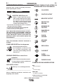
COLD FEED
POSITIVE OUTPUT
NEGATIVE OUTPUT
PROTECTIVE
GROUND
WARNING OR
CAUTION
DANGEROUS
VOLTAGE
SHOCK
HAZARD
WELDING
FUMES
EXPLOSION
GAS INPUT
WORK
CONNECTION
PURGE BY GAS
SAFETY PRECAUTIONS
Read this entire section of operating instructions
before operating the machine.
ELECTRIC SHOCK can kill.
• Unless using cold feed feature,
when feeding with the gun trigger,
the electrode and drive mechanism
are always electrically energized
and could remain energized several
seconds after welding ceases.
• Do not touch electrically live parts or electrodes
with your skin or wet clothing.
• Insulate yourself from the work and ground.
• Always wear dry insulating gloves.
-------------------------------------------------------------
ONLY QUALIFIED PERSONS SHOULD INSTALL,
USE OR SERVICE THIS EQUIPMENT. READ AND
FOLLOW THE MANUFACTURER’S INSTRUC-
TIONS, EMPLOYER’S SAFETY PRACTICES AND
MATERIAL SAFETY DATA SHEETS (MSDS) FOR
CONSUMABLES.
-----------------------------------------------------------
READ THIS WARNING, PROTECT YOURSELF &
OTHERS.
FUMES AND GASES can be dangerous.
• Keep your head out of fumes.
• Use ventilation or exhaust at the
arc, or both,to keep fumes and
gases from your breathing zone and
general area.
WELDING SPARKS can cause fire or
explosion.
• Do not weld near flammable material.
• Do not weld on containers which have
held flammable material.
ARC RAYS can burn.
• Wear eye, ear, and body protection.
-----------------------------------------------------------
Observe additional guidelines detailed in the
beginning of this manual.
WARNING
GRAPHIC SYMBOLS THAT APPEAR ON
THIS MACHINE OR IN THIS MANUAL
COMMON WELDING ABBREVIATIONS
WFS
• Wire Feed Speed
CV
• Constant Voltage
GMAW (MIG)
• Gas Metal Arc Welding
FCAW (Innershield or Outershield)
• Flux Core Arc Welding

B-2
OPERATION
B-2
eCELL™ WIRE DRIVE SYSTEM
RECOMMENDED PROCESSES
•
GMAW AND GMAW-STT
• FCAW
PROCESS LIMITATIONS
• The eCell™ Wire Drive is not recommended for
GTAW, CAG, SMAW, SAW
• The eCell™ Wire Drive is not compatible with push-
pull equipment.
REQUIRED EQUIPMENT
All power sources must be part of the eCell™ system.
These include:
• PowerWave 355M
• PowerWave 455M
• PowerWave 455M/STT
• PowerWave 455M Robotic
• PowerWave 455M/STT Robotic
EQUIPMENT LIMITATIONS
• Maximum GMAW gun length =25’ (7.6m)
• Maximum conduit length = 25' (7.6m)
• Maximum total control cable length = 100ft (31m)
• The eCell™ Wire Drive works only with ArcLink
equipment.
• Other gun bushings are required for welding guns
that do not have a "Lincoln" back-end.
PRODUCT DESCRIPTION
General Physical Description
The eCell™ Wire Drive System is the wire feeder for
the eCell™. It consists of a 4 roll wire drive with con-
nections for the torch, electrode conduit and shielding
gas. The small, lightweight feeder mounts at the rear
of the eCell™.
General Functional Description
The eCell™ Wire Drive System is a robotic wire drive
that operates only with the eCell™. All welding para-
meters (WFS, voltage, etc.) are set through the robot-
ic controller. Integrated in the wire drive is a robotic
wire drive module. The eCell™ Wire Drive module
communicates with the robotic control and Power
Wave power source via ArcLink.
The wire drive is capable of wire feed speeds of 50 –
800 ipm. Accurate speed control is obtained with a
tachometer integrated in the motor. The wire drive is
capable of feeding both forward and reverse.
The heart of the eCell™ Wire Drive is the MaxTrac™
4 roll wire drive.
This new 4 roll drive MaxTrac™ technology delivers
great feeding because:
• Patent pending drive rolls improve traction.
• The precision machined, rigid aluminum
alloy frame results in maximum drive roll
clamping pressure.
• Drive hubs with steel inner cores have 3 ball
bearings inside each hub.
• The drive hubs are supported by large, heat
treated and ground shafts for maximum
rigidity and accurate drive roll alignment.
• Patent pending dual spring pressure arms
have sensitivity for feeding soft wires without
crushing them, and have plenty of compres-
sion force for feeding solid or stiff wires.
Easy to configure, easy to service parts give
MaxTrac™ drives the edge in productivity.
• Patented split wire guides fully support the
wire and virtually eliminate birdnesting.
• No tools required to change the drive rolls
and wire guides.
• Changeable gun bushings easily accept
guns from many manufacturers.
• Brass-to-brass connections between the
electrode connection and the gun minimize
voltage drop variations, resulting in consis-
tent arc performance all day, every day.
Functions that can be operated without the robot con-
troller are gas purge and cold feed.
La page est en cours de chargement...
La page est en cours de chargement...
La page est en cours de chargement...
La page est en cours de chargement...
La page est en cours de chargement...
La page est en cours de chargement...
La page est en cours de chargement...
La page est en cours de chargement...
La page est en cours de chargement...
La page est en cours de chargement...
La page est en cours de chargement...
La page est en cours de chargement...
La page est en cours de chargement...
-
 1
1
-
 2
2
-
 3
3
-
 4
4
-
 5
5
-
 6
6
-
 7
7
-
 8
8
-
 9
9
-
 10
10
-
 11
11
-
 12
12
-
 13
13
-
 14
14
-
 15
15
-
 16
16
-
 17
17
-
 18
18
-
 19
19
-
 20
20
-
 21
21
-
 22
22
-
 23
23
-
 24
24
-
 25
25
-
 26
26
-
 27
27
-
 28
28
-
 29
29
-
 30
30
-
 31
31
-
 32
32
-
 33
33


Lincoln Electric E-Cell Wire Drive System Mode d'emploi
- Catégorie
- Système de soudage
- Taper
- Mode d'emploi
dans d''autres langues
Documents connexes
-
Lincoln Electric Eagle 10,000 Mode d'emploi
-
-
-
-
Lincoln Electric IM756-A Manuel utilisateur
-
Lincoln Electric LN-25 Pro Mode d'emploi
-
-
-
-
Lincoln Electric AutoDrive 4R100 Mode d'emploi