wattstopper NB-Router Guide d'installation
- Taper
- Guide d'installation

1
Wattstopper
®
DLM Segment Network to IP Router
Installation Instructions • Instructions d’Installation • Instrucciones de Instalación
No: 29658– 12/19 rev. 1
Catalog Numbers • Les Nombre de Catalogue • Números de Catálogo: NB-ROUTER
Country of Origin: Made in USA • Pays d’origine: Fabriqué en USA • País de origen: Hecho en Estados Unidos de América
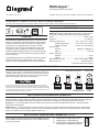
OVERVIEW
The NB-ROUTER (BASRT-B-WS) provides a connection point
between a single Digital Lighting Management (DLM) segment
network and an Ethernet LAN. The router has a rugged metal
enclosure with an integral DIN rail mounting clip. The NB-
ROUTER provides a browser-based interface for set up and
configuration. Using an assigned IP address and additional
Ethernet and BACnet MS/TP settings, the device automatically
routes network communication between the segment network
and an IP network.
The NB-ROUTER is perfect for applications with DLM segment
networks originating from multiple locations, or for routing a
segment network to a BAS via BACnet IP or BACnet Ethernet.
SPECIFICATION
POWER CONNECTION
The NB-ROUTER requires 24 VAC or 24 VDC while drawing no
more than 4 VA of power. The recommended conductor size is 16–
18 AWG. COM is directly connected to zero volts and the chassis is
DC isolated from zero volts. Input connections are reverse-polarity
protected. See figure to the right for power options.
MS/TP PHYSICAL LAYER BIAS AND TERMINATION
End-of-Line termination (120Ω) is normally applied at both ends of the MS/TP bus, especially when using long cable segments and
faster data rates. Fail-safe voltage bias (200mV) ensures stable MS/TP operation. The BASrouter is shipped with fail-safe voltage bias
and EOL termination applied. Depending on the application, these can be changed by removing jumpers inside of the case.
End Device – In a router application where the location of the router is at the end of the MS/TP bus segment – both bias and EOL
termination must be applied.
Middle Device – In a router application where the location of the router is anywhere between the end MS/TP devices (in the middle
of the bus), termination jumper should be removed. Fail-safe voltage bias jumpers could be left in place depending on whether other
devices on the MS/TP bus are providing additional bias or not.
Input Voltage (±10%)......................................................24VAC/VDC
Power..........................................................................2 W DC, 4VAC
Frequency........................................................................47-63Hz AC
Operating Temperature...........................32° to 140°F (0° to 60°C)
Storage Temperature..................23° to 176°F (-40° to 80°C)
Relative Humidity.......................10-95% (non-condensing)
Physical Layer
Ethernet........................................10BASE-T, 100BASE-TX
MS/TP..................................................................EIA-485
Cable Length Limit
Ethernet......................................................................100 m
MS/TP.......................................................................1200 m
MS/TP Data Rate (bps)..........................9600, 19200, 38400, 76800
MS/TP Node Limit...................................................254 Devices total,
31 Full-load devices per segment
COM HI HIB
24 VDC
DC POWERED
COM HI HIB
Primary
Backup
COM HI HIB
24 VAC
Primary
AC POWERED REDUNDANT
POWER
Either Source
24 VAC or 24 VDC
Connecting chassis to earth or using
a backup source is always optional
AC POWERED WITH
GROUNDED SECONDARY
COM HI HIB
24 VAC
Primary
Internally, this device utilizes a half-wave rectifier and therefore can only share the
same AC power source with other half-wave rectified devices. Sharing a common DC
power source is also possible. Sharing AC power with full-wave rectified devices is NOT
recommended. Devices powered from a common AC source could be damaged if a mix
of half-wave and full-wave rectified devices exists.
MS/TP PHYSICAL LAYER BIAS AND TERMINATION (continued)
U
T
D
U
T
D
Install jumper to apply pull-up bias
Install jumper to terminate bus
Install jumper to apply pull-down bias
(all jumpers are installed by default)
Three configuration jumpers are located inside the NBRouter’s case
near the MS/TP connector. Removing the cover provides access to
the 6-pin jumper block.
NOTE: NB-ROUTER ordered within the network enclosure comes
pre-powered, otherwise order NB-PS power supply separately

2
+
_
SC
MS/TP
D+ D-
24 V Gnd
Do NOT connect
shield to SC pin!
Connect shield to earth at only one point
Up to 31 Full-load
MS/TYP Field
Devices
Termination and
bias applied
internally
NB-ROUTE
R1
20 Ω
Power
HIB
HI
COM
HI HI
LO
24 VAC
Earth
D+ D-
24 V Gnd
LO
24 VAC
Earth
HI
LO
24 VAC
Earth
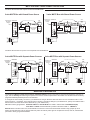
MS/TP PHYSICAL LAYER CONNECTION OPTIONS
For MS/TP devices that share a power source with the NB-Router
For MS/TP devices that use a power source separate from the NB-Router
2-wire MS/TP Bus with Shared Power Source
2-wire MS/TP Bus with Separate Power Sources
3-wire MS/TP Bus with Shared Power Source
3-wire MS/TP Bus with Separate Power Sources
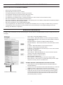
WEBPAGE CONFIGURATION
The NB-Router BACnet routing function will be disabled by default until the unique factory-programmed password is changed. On
login, click the Security tab and change the password to an 8-10 character alphanumeric value which must be different than the factory-
programmed default password printed on the side label.
To configure the router initially, connect it to your Windows PC using an Ethernet cable and set the PC’s IP and subnet mask in Local
Area Connection –> Properties. In the Internet Protocol Version 4 (TCP/IPv4) settings of your Windows PC, specify an IP address and a
Subnet mask in the same subnet as the BASrouter (e.g. 192.168.92.5 /24).
NB-Router’s factory-programmed: Default IP address is 192.168.92.68 and a Class C subnet mask of 255.255.255.0 (/24)
User Name is: admin and the Password is printed on the Serial Label i.e. “1W535317”
Reset IP switch is located on the front, underneath RJ-45 connector. Press and hold the Reset IP button using a paper clip for at
least 3 seconds while the router is powered. Remove power and restore power again to complete the reset IP, User ID, and Password
procedure to factory-programmed defaults.
+
_
SC
MS/TP
D+ D-
24 V Gnd
Do NOT connect
shield to SC pin!
Connect shield to earth at only one point
Up to 31 Full-load
MS/TYP Field
Devices
Termination and
bias applied
internally
NB-ROUTE
R1
20 Ω
Power
HIB
HI
COM
HI
LO
24 VAC
(optional)
D+ D-
24 V Gnd
+
_
SC
MS/TP
Do NOT connect
shield to SC pin!
Connect shield to earth at only one point
Up to 31 Full-load
MS/TYP Field
Devices
Termination and
bias applied
internally
NB-ROUTER 120 Ω
Power
HIB
HI
COM
HI
LO
24 VAC
(optional)
D+ C D-
24 V Gnd
D+ C D-
24 V Gnd
HI
LO
24 VAC
(optional)
HI
LO
24 VAC
(optional)
+
_
SC
MS/TP
Do NOT connect
shield to SC pin!
Connect shield to earth at only one point
Up to 31 Full-load
MS/TYP Field
Devices
Termination and
bias applied
internally
NB-ROUTER 120 Ω
Power
HIB
HI
COM
HI
LO
24 VAC
(optional)
D+ C D-
24 V Gnd
D+ C D-
24 V Gnd

3
Check box to Enable Routing
To enable routing of the MS/TP you must check Routing box in the web browse of the NB-ROUTER as well as accepting the EULA (see
next page).
NB-ROUTER CONFIGURATION
START UP CHECKLIST: CONFIGURE BACNET NETWORKS
DEFAULT DEVICE IDs and NETWORK NUMBERS
• Device ID are in the range 0-4194302
• Network Numbers are in the range of 1-65534
• The Segment Manager has a default Local Device ID of 861234
• The local MS/TP networks have default numbers: 8611, 8612, 8613
• The IP Network 1 has default number 1 (normal for networks)
• The IP Network 2 has a default number 1 [ invalid ] (should be set to match network chosen for BACnet routers)
• UDP Port for IP Network 1 and IP Network 2 can’t be the same
• UDP Port for IP Network 1 is NOT the BACnet default. It has purposely been set to 0xBAC1 (47809) rather than 0xBAC0 (47808) to
prevent other vendors from discovering it by accident
• UDP Port for IP Network 2 is set to default 0xBAC0 (47808)
• If only using MSTP ports, then BACnet setup is easy. Make sure the MSTP ports you are using are enabled. Then go to discover.
• If using BACnet routers connected to the same network as the second network port on the Segment Manager, then do the
following: (See NB-Router Configuration)
• Device Name - MUST BE UNIQUE on the site
• Device Instance - MUST BE UNIQUE on the site. If routing is ever allowed
through Segment Manager to this network, there will be problems if instance
numbers collide
• BACnet/IP UDP Port - Default is hex BAC0 (47808) for BACnet
• BACnet/IP Network 1 - Must match all devices on this same Ethernet switch
subnet
• IP Address - MUST BE UNIQUE on the local Ethernet switch
• IP Subnet - usually 24 (same as 255.255.255.0)
• IP Gateway - Correct Gateway for this network (If no route to other networks,
make same as IP Address)
• MS/TP Mac - Usually 0 for router
• MS/TP Network - MUST BE UNIQUE for the site, that includes corporate
network on other side of Segment Manager
• Max Master - Default is 127-best to leave it
• Max Info Frames - Default is 32
• MS/TP Baudrate - Default is 38400 (our devices do support 76800)
• MS/TP Tolerance - Strict is faster. It is possible that setting of lenient “might”
help if there are many devices on the MS/TP wire
SEGMENT MANAGER CONFIGURATION FOR BACNET ROUTERS
1. Set IP Network 2 to the same Network Number as the BACnet Router’s
BACnet/IP Network 1
2. Set UDP Port to same as BACnet Router’s BACnet/IP UDP Port 1 (should be
0xBAC0 on JACE, CC Router does not need 0x in front of BAC0)
3. NOTE: Each vendor of BACnet devices has a vendor ID. The Wattstopper
vendor ID is 86. The use of the number 86 prefixing the network numbers
and device IDs helps ensure they are unique on the site. If this network is
ever connected to the site network with HVAC and other devices, the 86
prefix will help identify our devices.

4
800.879.8585
www.legrand.us/wattstopper
No. 29658 – 12/19 rev. 1
© Copyright 2019 Legrand All Rights Reserved.
© Copyright 2019 Tous droits réservés Legrand.
© Copyright 2019 Legrand Todos los derechos reservados.
Wattstopper warranties its products to be free of
defects in materials and workmanship for a period
of one (1) year. There are no obligations or liabilities
on the part of Wattstopper for consequential
damages arising out of, or in connection with,
the use or performance of this product or other
indirect damages with respect to loss of property,
revenue or profit, or cost of removal, installation or
reinstallation.
Wattstopper garantit que ses produits sont
exempts de défauts de matériaux et de fabrication
pour une période de un (1) ans. Wattstopper ne
peut être tenu responsable de tout dommage
consécutif causé par ou lié à l’utilisation ou
à la performance de ce produit ou tout autre
dommage indirect lié à la perte de propriété, de
revenus, ou de profits, ou aux coûts d’enlèvement,
d’installation ou de réinstallation.
Wattstopper garantiza que sus productos están
libres de defectos en materiales y mano de obra por
un período de un (1) año. No existen obligaciones
ni responsabilidades por parte de Wattstopper
por daños consecuentes que se deriven o estén
relacionados con el uso o el rendimiento de este
producto u otros daños indirectos con respecto a
la pérdida de propiedad, renta o ganancias, o al
costo de extracción, instalación o reinstalación.
WARRANTY INFORMATION INFORMATIONS RELATIVES À LA GARANTIE INFORMACIÓN DE LA GARANTÍA
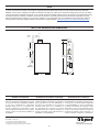
MULTI-LINE DRAWINGS AND DIMENSIONS
2.74”
(70mm)
1.00”
(26mm)
0.59”
(15mm)
4.85”
(123mm)
0.97”
(25mm)
TS-35
DIN RAIL
0.28”
(7mm)
2.42”
(61mm)
center
center
“In order to enhance the security of our products, Legrand ships its products with all insecure ports closed and insecure protocols
disabled. You are free to configure your device as needed, but in doing so note that you may be decreasing the security of your device
and any information contained in the device. As you modify the device’s default settings, keep in mind how this may impact the security
of the device and your network. In addition, you should use caution in connecting your device to the Internet, especially if you have
altered the default security settings. If you have any questions or concerns about how your modifications of the device may affect its
security, please contact the Legrand customer service team at 1-800-879-8585 / https://www.legrand.us/support/wattstopper.aspx”
EULA
-
 1
1
-
 2
2
-
 3
3
-
 4
4


wattstopper NB-Router Guide d'installation
- Taper
- Guide d'installation
dans d''autres langues
Documents connexes
Autres documents
-
Legrand LMBC-600- DLM Wireless Network Bridge Module Guide d'installation
-
-
-
 Setra Systems Power Meter (Multi-Load) Mode d'emploi
-
-
Honeywell 301c Manuel utilisateur
-
Eaton DG1-357D6FB-C21C Communications Manual
-
-
-
SYNAPSE Control-485 Controller for Thermostats Manuel utilisateur
