
Installation
INSTRUCTIONS
THERMADOR.COM
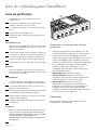
Professional Series Rangetops


THERMADOR.COM
Installation
INSTRUCTIONS
Table of contents (English)................................................................ 2
Table de matières (Français)............................................................ 19
Índice de materias (Español) ........................................................... 38
Models |
Modèles |
Modelos:
PCG305W
PCG366W
PCG364WD
PCG364WL
PCG486WL
PCG486WD
Professional Series Rangetops

Page. 2
This THERMADOR
®
appliance is made by
BSH Home Appliances Corporation
1901 Main Street, Suite 600
Irvine, CA 92614
Questions?
1-800-735-4328
www.thermador.com
We look forward to hearing from you!
Table of
CONTENTS
Safety ..................................................................................... 3
Important safety instructions........................................... 3
Installation instructions ........................................................... 5
Planning information ....................................................... 5
Ventilation requirements................................................. 5
Installation clearances...................................................... 6
Unpacking and setting the rangetop .............................. 11
Gas requirements and hookup........................................ 12
Electrical requirements and connection.......................... 14
Low Backguard installation (optional) ............................. 15
Burner test....................................................................... 16
Installer checklist..................................................................... 18
Final check list.................................................................. 18
Support, accessories, and parts .................................back page
Safety
DEFINITIONS
9 WARNING
This indicates that death or serious injuries may occur as a
result of non-observance of this warning.
9 CAUTION
This indicates that minor or moderate injuries may occur as a
result of non-observance of this warning.
NOTICE: This indicates that damage to the appliance or
property may occur as a result of non-compliance with this
advisory.
Note: This alerts you to important information and/or tips.

Page. 3
Safety
9 IMPORTANT SAFETY INSTRUCTIONS
READ AND SAVE THESE INSTRUCTIONS
INSTALLER: Save these Instructions for the Local Gas
Inspector’s use. Please leave these Installation Instructions
with this unit for the owner. Show the owner the location
of the circuit breaker or fuse. Mark it for easy reference.
OWNER: Please retain these instructions for future
reference. Before using your appliance, be sure to read
this manual.
WARNING
ELECTRICAL SHOCK HAZARD
• Disconnect power before installing or
servicing. Before turning power ON, be sure
that all controls are in the OFF position.
• DO NOT remove connections.
• DO NOT use an extension cord.
• Improper grounding can result in a risk of
electric shock.
• Failure to follow these instructions can result
in death, fire, or electrical shock.
Local codes vary. Installer is responsible for ensuring that
the installation, gas connections, and grounding comply
with all applicable codes. Failure to follow appropriate
local codes and regulations may void the warranty.
The installation of appliances designed for manufactured
(mobile) home installation must conform with the
Manufactured Home Construction and Safety Standard,
Title 24 CFR, Part 3280 [formerly the Federal Standard for
Mobile Home Construction and Safety, Title 24, HUD {Part
280}] or with local codes where applicable.
The installation of appliances designed for Recreational
Park Trailers must conform with state or other codes or, in
the absence of such codes, with the Standard for
Recreational Park Trailers, ANSI A119.5.
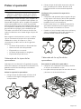
Examine the appliance after unpacking it. In the event of
transport damage, do not plug it in.
Remove all tape and packaging before using the
appliance. Dispose of packaging in an environmentally-
responsible manner. Never allow children to play with
packaging material.
This appliance must be grounded. Grounding reduces the
risk of electric shock by providing a safe pathway for
electric current in the event of a short circuit.
The appliance, when installed, must be electrically
grounded in accordance with local codes or, in the
absence of local codes, with the National Electrical Code,
NFPA 70 latest edition, or the Canadian Electric Code,
CSA C22.1-02.
DO NOT install this appliance outdoors.
For Massachusetts Installations:
• Installation must be performed by a qualified or
licensed contractor, plumber or gas fitter qualified or
licensed by the state, province or region where this
appliance is being installed.
• Shut-off valve must be a “T” handle gas cock.
• Flexible gas connector must not be longer than 36''
(914 mm).
Verify the type of gas supplied to the location. Ensure that
the appliance is connected to the type of gas for which it
is certified.
This appliance is capable of being safely placed in
operation in the event of a power failure. Only the
standard top burners can be manually lit.
WARNING
If the information in this manual is
not followed exactly, a fire or
explosion may result causing
property damage, personal injury or
death.
-- DO NOT store or use gasoline or other
flammable vapors and liquids in the
vicinity of this or any other appliance.
-- WHAT TO DO IF YOU SMELL GAS
• DO NOT try to light any appliance.
• DO NOT touch any electrical switch.
• DO NOT use any phone in your
building.
• Immediately call your gas supplier from
a neighbor’s phone. Follow the gas
supplier’s instructions.
• If you cannot reach your gas supplier,
call the fire department.
-- Installation and service must be
performed by a qualified installer, service
agency or the gas supplier.

Page. 4
9 IMPORTANT SAFETY INSTRUCTIONS
READ AND SAVE THESE INSTRUCTIONS
Always keep appliance area clear from combustible
materials, gasoline and other flammable vapors and
liquids.
Natural Gas — 7 inch water column. (17.4 mb) min., 14
inch (34.9 mb) maximum
Propane Gas — 11 inch water column. (27.4 mb) min., 14
inch (34.9 mb) maximum
CAUTION
When connecting the unit to propane gas, make certain
the propane gas tank is equipped with its own high-
pressure regulator in addition to the pressure regulator
supplied with the appliance. The maximum gas pressure
to this appliance must not exceed 14.0'' water column
(34.9 mb) from the propane gas tank to the pressure
regulator.
This appliance complies with one or more of the
following Standards:
• UL 858, The Standard for the Safety of Household
Electric Ranges
• ANSI Z21.1, The American National Standard for
Household Cooking Gas Appliances
• CAN1-1.1-M81, Domestic Gas Ranges
• CSA C22.2 No. 61, Household Cooking Ranges
Check local building codes for the proper method of
appliance installation. Local codes vary; it is the
responsibility of the installer to ensure installation is in
accordance with these codes. Installation, electrical
connections, and grounding must comply with all
applicable codes.
In the absence of local codes the appliance should be
installed in accordance with the National Electric Code
NFPA 70 current issue and National Gas Code NFPA 54/
ANSI Z223.1 – current issue. In Canada, installation must
be in accordance with the Canadian Electric Code, CSA
C22.1-02 and the CAN 1-B149.1 and .2 – Installation
Codes for Gas Burning Appliances and/or local codes.
Proposition 65 Warning
This product may contain a chemical known to the State of
California, which can cause cancer or reproductive harm.
Therefore, the packaging of your product may bear the
following label as required by California:
REAR CLEARANCE REQUIREMENTS:
• To avoid staining on the back wall, high temperature,
non-porous construction materials suitable for use in a
cooking environment are recommended.
• Models PCG305xx, PRD305xx, and PRD606xx are
suitable for 0'' rear clearance to combustible surfaces.
• All Other Models:
• When using the included Island Trim a minimum
6" (152 mm)* rear clearance is required to a
combustible surface*.
• When installing against a combustible surface, a
Thermador
®
Low Backguard is required for a 0''
rear clearance to the combustible surface. A
Thermador Low Backguard must be purchased
separately.
• A rear clearance to a surface covered in a non-
combustible material (metal, ceramic tile, brick,
marble, or stone)
*
is 0" when using the included
Island Trim.
*Clearances of less than 6'' (152 mm) should be approved by the
local codes and/or by the local authority having jurisdiction.
Clearances from non-combustible materials are not part of the
ANSI Z21.1 scope and are not certified by CSA.
WARNING
To avoid possible burn or fire hazard, a backguard
designed specifically for this appliance should be installed
whenever the appliance is used.
WARNING
To eliminate risk of burns or fire caused by reaching over
heated surface units, cabinet storage located above the
surface units should be avoided.
CAUTION
This unit is designed as a cooking appliance. Based on
safety considerations, never use it for warming or heating
a room. Doing so may result in carbon monoxide
poisoning and overheating the appliance.
WARNING
Never Operate the Top Surface Cooking Section of this
Appliance Unattended
• Failure to follow this warning statement could result
in fire, explosion, or burn hazard that could cause
property damage, personal injury, or death.
• If a fire should occur, keep away from the appliance
and immediately call your fire department. DO NOT
ATTEMPT TO EXTINGUISH AN OIL/GREASE FIRE
WITH WATER.
State of California Proposition 65 Warning:
: WARNING
Cancer and Reproductive Harm -
www.P65Warnings.ca.gov

Page. 5
Installation instructions
Planning information
9 CAUTION
To prevent possible damage to cabinets and cabinet
finishes, use only materials and finishes that will not
discolor or divide into layers. Materials should be able
to withstand temperatures up to 194 °F (90 °C). Heat
and moisture resistant adhesive must be used if the
product is to be installed in laminated cabinetry.
Check with the manufacturer to ensure materials meet
these requirements.
Before using your appliance, be sure to read this manual.
Pay special attention to the
Important Safety Instructions
located at the beginning of the manual.
Any opening in the wall behind the appliance and in the
floor under the appliance shall be sealed.
Tools needed
• 7/16'' box wrench
• Level
• T-20 Torx screwdriver
• Protective gloves
• 12'' adjustable wrench
• Tape measure
• Marking instrument
Items required
• 3/4'' (19 mm) flex line
• Pipe compound/tape
IMPORTANT: There is a possibility to discolor the back
wall under certain cooking conditions.
Ventilation requirements
9 WARNING
This appliance should not be installed with a
ventilation system that directs air in a downward
direction toward the appliance. This type of
ventilation system may cause ignition and combustion
problems with the appliance resulting in personal
injury, property damage, or unintended operation.
Ventilating systems that direct the air upwards do not
have any restriction.
Refer to the Ventilation Planning Guide for approved
ventilation combinations.
It is strongly recommended that this appliance be installed
in conjunction with a Thermador vent hood. Due to the
high heat capability of this unit, particular attention should
be paid to the hood and duct work installation to assure it
meets local building codes.
Downdraft ventilation should not be used. The Ventilation
Planning Guide indicates the ventilation hood options and
blower capacity guidelines that are recommended for use.
Due to the high heat of the rangetop burners, installing a
microwave oven with a ventilation system over the
rangetop is not recommended on anything other than the
30'' 5–Burner. Refer to OTR manufacturer’s installation
manual for clearances.
Ventilation hoods and blowers are designed for use with
single wall ducting. However, some local building codes or
inspectors may require double wall ducting. Consult local
building codes and/or local agencies before starting to
assure that hood and duct installation will meet local
requirements.
NOTICE: Most range hoods contain combustible
components which must be considered when planning the
installation.
Ventilation preparation
To prepare for the ventilation
1. Select hood and blower models:
• For wall installations, the hood width must, at a
minimum, equal the width of the range/rangetop.
Where space permits, a hood larger in width than
the range/rangetop may be desirable for
improved ventilation performance.
• For island installations, the hood width should
overhang the width of the range/rangetop by a
minimum of 3'' (76 mm) on each side.
2. Hood placement:
• For best smoke elimination, the lower edge of the
hood should be installed 30'' (762 mm) above the
range cooking surface.
• If the hood contains any combustible materials
(i.e. a wood covering), it must be installed a
minimum of 36'' (914 mm) above the cooking
surface.
3. Consider make-up air:
• Due to the high volume of ventilation air, a source
of outside replacement air is recommended. This
is particularly important for tightly sealed and
insulated homes.
• A qualified heating and ventilating contractor
should be consulted.

Page. 6
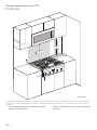
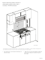
Installation clearances
• To ensure professional results, the cabinet and
countertop openings should be prepared by a
qualified cabinet worker.
• The same clearances apply to island installations,
except for the overhead cabinets, which must have a
space wide enough to accept the island hood.
• See the Ventilation Planning Guide for recommended
hood options. Due to the high heat of the burners,
installing a microwave oven with a ventilation system
over the appliance is not recommended on anything
other than the 30'' 5–Burner. Refer to the OTR
manufacturer’s installation manual for clearances.
• The rangetop is designed to hang from the
countertop by its flanges. The countertop however
must be strong enough to support this rangetop. It
may be necessary to add a supporting cleat along
each side or a 2 x 4 corner brace (see page 10).
Another alternative would be to construct a deck to
set the rangetop on.
• The rangetop can be installed in various positions with
the front either flush or projecting, depending on the
countertop’s depth.
• The gas and electrical supply must be located in an
area that is accessible without requiring removal of the
rangetop.
• The shaded area behind the appliance indicates an
opportunity to discolor the back wall under certain
cooking conditions.
• There must be a minimum of 5'' (127 mm) side
clearance from the appliance to combustible vertical
surfaces above the 36'' (914 mm) counter height.
• Within the 5'' (127 mm) side clearance to combustible
vertical surfaces above 36'' (91.4 cm), the maximum
wall cabinet depth must be 13'' (330 mm).
• Wall cabinets within this 5'' (127 mm) side clearance
must be 18'' (45.7 cm) above the 36'' (914 mm) high
countertop.
• There is a 36'' (914 mm) minimum clearance required
between the top of the cooking surface and the
bottom of an unprotected cabinet. A 30'' (762 mm)
clearance can be used when the bottom of the wood
or metal cabinet is protected by not less than 1/4''
(6 mm) of a flame retardant material covered with not
less than No. 28 MSG sheet steel, 0.015'' (0.38 mm)
thick stainless steel, 0.024'' (0.61 mm) aluminum, or
0.02'' (0.51 mm) thick copper.
• Establish the centerline of the appliance’s desired
location. It should be the same as the center of the
overhead ventilation hood.
• Cut the openings for the following installations:
• Wall installation, see page 10.
• Island installation, see page 10.
REAR CLEARANCE REQUIREMENTS:
• To avoid staining on the back wall, high temperature,
non-porous construction materials suitable for use in a
cooking environment are recommended.
• Models PCG305xx, PRD305xx, and PRD606xx are
suitable for 0'' rear clearance to combustible surfaces.
• All Other Models:
• When using the included Island Trim a minimum
6" (152 mm)* rear clearance is required to a
combustible surface*.
• When installing against a combustible surface, a
Thermador
®
Low Backguard is required for a 0''
rear clearance to the combustible surface. A
Thermador Low Backguard must be purchased
separately.
• A rear clearance to a surface covered in a non-
combustible material (metal, ceramic tile, brick,
marble, or stone)*
is 0'' when using the included
Island Trim.
*Clearances of less than 6'' (152 mm) should be approved by the
local codes and/or by the local authority having jurisdiction.
Clearances from non-combustible materials are not part of the
ANSI Z21.1 scope and are not certified by CSA.
NOTES:
• If a solid side cabinet wall exists on one or both sides,
you will need to notch the front corner of the cabinet
to match the countertop notch and to allow clearance
for the rangetop front (see Detail A, page 10).
• If a supporting deck is used, the sides or bottom of
the cutout may be solid combustible or non-
combustible material. If the bottom is solid, provide a
12'' by 12'' (305 mm x 305 mm) cutout in the left rear
corner of the supporting deck. This will provide
clearance for the gas inlet and power cord.
• Always keep appliance area clean and free from
combustible materials, gasoline and other flammable
vapors and liquids.
• DO NOT obstruct the flow of combustion and
ventilation air to the unit.

Page. 7
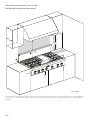
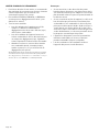
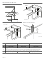
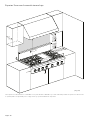
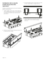
Clearance requirements with a Low
Backguard (purchased separately)
as defined in the “National Fuel Gas Code” (ANSI Z223.1, Current Edition). Clearances from non-combustible materials are not part of the ANSI Z21.1
scope and are not certified by CSA. Clearances of less than 6'' (152 mm) should be approved by the local codes and/or by the local authority having
jurisdiction.
1
8" (457)
1
8"
(45
7
)
1
8" (457)
0
"
0
"
0
"
36" or 48"
( 914 or 1,219 )
36" or 48"
( 914 or 1,219 )
36" or 48"
( 914 or 1,219 )
13"
(330)
13"
(330)
13"
(330)
0
"
0
"
0
"
30" (762) –
40" (1016)
30" (762) –
40" (1016)
30" (762) –
40" (1016)
0"
0"
5
" (12
7
)
inches (mm)

Page. 8
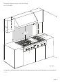
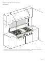
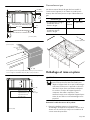
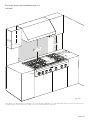
Clearance requirements with the island
trim (included)
as defined in the “National Fuel Gas Code” (ANSI Z223.1, Current Edition). Clearances from non-combustible materials are not part of the ANSI Z21.1
scope and are not certified by CSA. Clearances of less than 6'' (152 mm) should be approved by the local codes and/or by the local authority having
jurisdiction.
5
" (12
7
)
18"
(457)
18"
(
4
5
7
)
18"
(457)
30" (762) –
40" (1016)
30" (762) –
40" (1016)
30" (762) –
40" (1016)
0"0"0"
0"0"0"
36" or 48"
(914 or 1,219 )
36" or 48"
(914 or 1,219 )
36" or 48"
(914 or 1,219 )
13"
(330)
13"
(330)
13"
(330)
6" (152)6" (152)6" (152)
inches (mm)

Page. 9
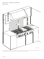
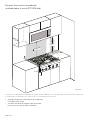
Clearance requirements with OTR –
PCG305 ONLY
• 30" (762 mm) minimum to non-combustible material
above the Cooking Surface.
• * Refer to OTR manufacturer’s installation manual for
clearances.
as defined in the “National Fuel Gas Code” (ANSI Z223.1, Current Edition). Clearances from non-combustible materials are not part of the ANSI Z21.1
scope and are not certified by CSA. Clearances of less than 6'' (152 mm) should be approved by the local codes and/or by the local authority having
jurisdiction.
1
8" (457)
1
8"
(45
7
)
1
8" (457)
0
"
0
"
0
"
30" (762)
30" (762)
30" (762)
0
"
0
"
0
"
*
30" (762)
*
30" (762)
*
30" (762)
0"
0"
5
" (12
7
)
13"
(330)
13"
(330)
13"
(330)
inches (mm)

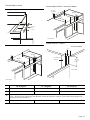
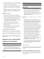
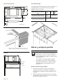
Page. 10
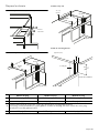
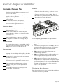
30'' Rangetop 36'' Rangetop 48'' Rangetop
A 29-15/16'' (760 mm) 35-15/16'' (913 mm) 47-15/16'' (1,218 mm)
B 3/8'' (10 mm) 3/8'' (10 mm) 7/8'' (22 mm)
C
0'' (0 mm) Control panel projecting 1
½'' (38 mm) from base cabinet face.
11/16'' (18 mm) Notch required for standard 24'' (610 mm) deep base cabinet; Control panel projecting 13/16''
(20 mm) from base cabinet face.
D 29-1/8'' (740 mm) 35-1/8'' (892 mm)
46-1/4
'' (1,175 mm)
Countertop cutout
Installing side support cleats (both sides)
Wall installation with countertop backsplash
Counter
sunk
screws
Detail A
B
23
5
/
16
"
(592)
23
5
/
16
"
(592)
23
5
/
16
"
(592)
D
A
inches (mm)
Island installation without countertop backsplash
Detail A: front face of cabinet
Detail A
22
13
/16
"
(580)
22
13
/16
"
(580)
22
13
/16
"
(580)
¾" (19)
minimum
D
A
inches (mm)
2 x 4 Corner
Support
Corner Notch DetailCorner Notch DetailCorner Notch Detail
C
B
77
111111
//
161616
""
(195)(195)(195)
inches (mm)

Page. 11
Gas inlet location
A manual valve must be installed external to the
appliance, in an accessible location from the front, for the
purpose of shutting off the gas supply.
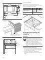
Unpacking and setting the
rangetop
9 CAUTION
Proper equipment and adequate manpower
must be used in moving the appliance to avoid
damage and/or personal injury. The unit is heavy
and should be handled accordingly.
Hidden surfaces may have sharp edges. Use
caution when handling the appliance. Failure to
do so may result in property damage or personal
injury.
Removing the rangetop from the pallet
1. Remove the outer carton and packing material from
the shipping base. Ensure that you have
all rangetop
components before proceeding.
2. Remove the cooking grates, griddle plate (if
applicable), and burner caps
to reduce the rangetop’s
weight.
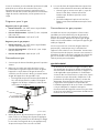
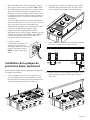
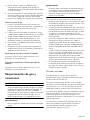
Side view of rangetop
Projecting from cabinet front
Installation of rangetop above Thermador warming drawers
Cabinet face for installation with
projecting control panel.
Cabinet face for installation
with flush control panel.
7
5
/
8
"
(194)
7
5
/
8
"
(194)
7
5
/
8
"
(194)
7
/
8
"
(22)
7
/
8
"
(22)
7
/
8
"
(22)
26¾" (680)26¾" (680)26¾" (680)
22½" (573)22½" (573)22½" (573)
½" (12.7)
side flange
½" (12.7)
side flange
½" (12.7)
side flange
inches (mm)
1½"
(38)
Front projects outward 13/16" (20) as
shown from standard 24" deep base.
Notch DepthNotch DepthNotch Depth
111111
//
161616
""
(18)(18)(18)
13
/
16
"
(20)
inches (mm)
Plywood support
Install additional
wood support along
front edge of cutout
2¾" (70)
min. between
cutouts
7
5
/
8
"
(194)
7
5
/
8
"
(194)
7
5
/
8
"
(194)
inches (mm)
Gas Inlet Location 30'' 36'' 48''
From left side to
centerline of gas inlet
6-3/8''
(152 mm)
11" (267 mm)
From rear to centerline of
gas inlet
2¼'' (54 mm)
¾" (19) ex line¾" (19) ex line¾" (19) ex line
½" (12.7) NPT½" (12.7) NPT½" (12.7) NPT
inches (mm)

Page. 12
3.
Leave protective film
over brushed-metal surfaces, to
protect finish from scratches, until the rangetop is
installed in its final position.
4. Use a Phillips head screwdriver to remove the screws
from the pallet brackets on the left and right sides of
the unit. Discard the screws and brackets after
removal.
Setting the rangetop
5. Attach the backguard, if applicable, before sliding the
appliance into the final installed position. (See “Low
backguard installation (optional)” on page 15.)
6. Lift and place the rangetop in the countertop
opening. Be careful not to pinch the power cord or
gas inlet. Care should be used not to scratch the
countertop.
7. Make sure that the power cord is free and hanging
loose.
8. The rangetop must be level for proper performance.
9. Replace the cooking grates, griddle plate, and burner
caps. Ensure that the burner caps are correctly seated
on the burner bases.
Assembling the griddle or grill (not all models)
Refer to the Use and Care Guide.
Gas requirements and hookup
9 CAUTION
The appliance must be isolated from the gas supply
piping system by closing its individual manual shut-off
valve during any pressure testing of the gas supply
piping system at test pressures equal to or less than 1/
2 psig (3.5kPa.).
9 WARNING
DO NOT use a flame of any kind to check for gas
leaks.
9 CAUTION
When connecting unit to propane gas, make certain
the propane gas tank is equipped with its own high
pressure regulator in addition to the pressure
regulator supplied with the appliance. The pressure of
the gas supplied to the appliance regulator must not
exceed 14" water column (34.9 mb).
IMPORTANT: Do not ground to a gas pipe.
• Verify the type of gas being used at the installation
site. Make certain the range matches the type of gas
available at this location.
• A metal flex line or fixed metal pipe shall be used to
connect gas to the appliance. If a metal gas line
cannot be used, consult your local certified electrician
or local electric codes for proper grounding.
• The gas supply connections shall be made by a
competent technician and in accordance with local
codes or ordinances. In the absence of local codes,
the installation must conform to the National Fuel Gas
Code ANSI Z223.1/NFPA54- current issue.
• A manual gas shut-off valve must be installed external
to the appliance, in a location accessible from the
front, for the purpose of shutting off the gas supply.
The supply line must not interfere with the back of the
unit. Make sure the gas supply is turned off at the
manual shut-off valve before connecting the
appliance.
• The installer should inform the owner of the location
of the gas shut-off valve. Make sure all users know
where and how to shut off the gas supply to the
rangetop.
High altitude
This appliance has been tested for operation up to an
altitude of 10,100 ft (3,078 m) elevation above sea level.
A high altitude kit is required for natural gas above 5,400
feet (1,646 m) elevation above sea level, and for propane
(LP) above 10,000 feet (3048 m) elevation above sea level.
If desired, for altitudes above 2,000 feet (610 m) elevation
above sea level, adjustments can be made to the
rangetop burners with an adjustment kit. If flame
performance is satisfactory, adjustment will not be
required. It is required that a Certified Professional make
the high altitude adjustments during installation.
See the back cover for information about service, parts,
and accessories.
Gas requirements
Natural gas requirements
• Inlet connection: 1/2'' NPT internal (Minimum 3/4''
dia. flex line)
• Supply pressure: 7'' min. to 14'' max. water column
(17.4 to 34.9 mb)
• Manifold pressure: 5'' water column (12.5 mb)
Propane gas requirements
• Inlet connection: 1/2'' NPT internal (minimum 3/4''
dia. flex line)
• Supply pressure: 11'' min. to 14'' max. water column
(27.4 mb to 34.9 mb)
• Manifold pressure: 10'' water column (24.9 mb)

Page. 13
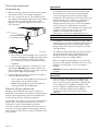
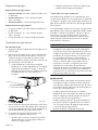
Natural gas connection
To connect the gas
1. Make sure the gas supply is turned off at the manual
shut-off valve before connecting the appliance.
2. Use a ¾'' (19 mm) flex line to connect between the
gas supply and the appliance gas inlet. The gas supply
line connection is located at the left rear of the
appliance. The appliance gas inlet connection is ½''
(12.7 mm) NPT.
• Use caution to avoid crimping the ¾'' (19 mm) flex
line when making bends. Suggested length of flex
line is 48" (1,219 mm); however, please check
local codes for your area's requirements before
installation.
3. Use pipe sealing compound or Teflon® tape on the
pipe threads. DO NOT apply sealing compound or
tape to flare fittings. Take care not to apply excessive
pressure when tightening the fittings.
4. Leak testing of the appliance shall be in accordance
with the following instructions.
• Turn on gas and check supply line connections for
leaks using a soap and water solution.
• Bubbles forming indicate a gas leak. Repair all
leaks immediately after finding them.
Propane (LP) gas connection
Rangetops are shipped by the factory to operate on
natural gas. They must be converted for use with propane.
Verify the type of gas being used at the installation site
matches the type of gas used by the appliance.
If the location site requires conversion from natural gas to
propane (LP), contact the dealer where the unit was
purchased or contact Thermador
®
to purchase a
conversion kit. Obey all instructions in this kit for correct
conversion of the gas regulator and settings for the gas
valves. Field conversion must be done by qualified service
personnel only.
9 WARNING
If a gas conversion kit is used, the kit shall be installed
by a qualified service personnel in accordance with
the manufacturer’s instructions and all applicable
codes and requirements of the authority having
jurisdiction. If the information in the instructions is not
followed exactly, a fire, explosion or production of
carbon monoxide may result causing property
damage, personal injury or loss of life. The qualified
service personnel is responsible for the proper
installation of the kit. The installation is not proper and
complete until the operation of the converted
appliance is checked as specified in the
manufacturer’s instructions supplied with the kit.
9 CAUTION
The appliance must be isolated from the gas supply
piping system by closing its individual manual shut-off
valve during any pressure testing of the gas supply
piping system at test pressures equal to or less than
1/2 psig (3.5kPa).
The appliance and its individual shut off valve must be
disconnected from the gas supply piping system
during any pressure testing of the system at test
pressures in excess of 1/2 psig (3.5kPa.).
When checking the manifold gas pressure, the inlet
pressure to the regulator should be at least 7.0" (17.4
mb) W.C. for natural gas or 11.0" (27.4 mb) for
propane.
DO NOT attempt any adjustment of the pressure
regulator.
9 CAUTION
Save the orifices removed from the appliance for
future use. When connecting unit to propane gas,
make certain the propane gas tank is equipped with
its own high pressure regulator in addition to the
pressure regulator supplied with the appliance. The
pressure of the gas supplied to the appliance
regulator must not exceed a 14'' water column
(34.9 mb).
¾" (19) external threads¾" (19) external threads¾" (19) external threads
½" (12.7) internal threads½" (12.7) internal threads½" (12.7) internal thr
eads
{
¾" (19)
Flex line
¾" (19)
Flex line
¾" (19)
Flex line
inches (mm)

Page. 14
Electrical requirements and
connection for gas units
9 WARNING
Before installing, turn power OFF at the service panel.
Lock service panel to prevent power from being
turned ON accidentally. Always disconnect appliance
from the electric supply either by disconnecting
power cord or shutting off the breaker at the service
panel before servicing the appliance.
9 WARNING
This product must be properly grounded.
9 WARNING
Electrical grounding instructions
This appliance is equipped with a three-prong
grounding plug for your protection against shock
hazard and should be plugged directly into a properly
grounded receptacle. DO NOT cut or remove the
grounding prong from this plug.
9 CAUTION
Improper grounding or reverse polarization will cause
malfunction (such as continuous sparking of the
burner igniters). This can damage the appliance and
can create a condition of shock hazard. If the
dedicated circuit is not correctly grounded and
polarized, it is the responsibility and obligation of the
installer and user to have the existing receptacle
changed to a properly dedicated grounded and
polarized receptacle. This must be accomplished in
accordance with all applicable local codes and
ordinances by a qualified electrician. In the absence of
local codes and ordinances, the receptacle
replacement shall be in accordance with the National
Electric Code.
INSTALLER — show the owner the location of the circuit
breaker. Mark it for easy reference.
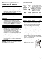
Electrical connection
Electrical supply circuit requirements
The cord supplied with the
gas ranges having an electric
griddle or grill requires a
NEMA 5-20 receptacle. All
other gas units require a
NEMA 5-15 receptacle.
• Before you plug in an electrical cord, be sure all
controls are in the OFF position.
• A neutral supply wire must be provided from the
power source (breaker) because critical range
components, including the surface burner spark
reignition modules, require it to operate safely and
properly.
• All 120 volt models must be plugged into a mating 3-
prong, grounding-type receptacle. The receptacle
must be connected to a properly dedicated grounded
and polarized electrical power supply rated at
120VAC, Single Phase, 60Hz.
• Observe all governing codes and ordinances when
grounding. In the absence of these codes or
ordinances observe National Electrical Code ANSI/
NFPA No. 70 current issue, or the relevant Canadian
Electric Code, CSA C22.1-02.
Model Voltage Dedicated circuit Phase
Pxx305Wx 120 VAC 15 Amps Single
Pxx366Wx 120 VAC 15 Amps Single
Pxx364WDx 120 VAC 20 Amps Single
Pxx364WLx 120 VAC 20 Amps Single
Pxx486WDx 120 VAC 20 Amps Single
Pxx486WLx 120 VAC 20 Amps Single
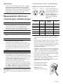
• Power cord and receptacle
should protrude no more than
2'' (51 mm) from the rear wall.
NOTE: Plug styles may vary.
NEMA 5-15 NEMA 5-20
G
G
N
N
2"
(51)

Page. 15
Low backguard installation
(optional)
9 WARNING
Fingers or hands could get pinched when installing
the backguard. Severe injury could result. Use
extreme caution and wear thick protective gloves to
avoid potential laceration to finger or hand while
sliding the backguard down onto the range.
9 WARNING
To reduce the risk of fire or injury to persons, check to
make sure all packaging has been removed from
accessory devices before use.
Installation methods will vary upon need. Before you
begin read these instructions carefully. Observe all local
codes and ordinances.
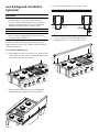
To install the low backguard
1. Depending on model, remove the 2 or 3 stainless Torx
screws in the front face of the included Island Trim. Lift
up to fully remove the Island Trim.
2. Slide the support brackets of the Low Backguard
between the two rangetop chassis back panels.
3. Secure the back with 8 x 1½'' (38 mm) screws.
4. Secure the front of the Low Backguard to the
rangetop with 2 or 3 x ½'' (12.7 mm) screws.
9½"
(239)
9½"
(239)
9½"
(239)

Page. 16
Burner test
9 WARNING
To prevent flare-ups and avoid the creation of harmful
by-products, do not use the cooktop without all
burner caps and all burner grates properly positioned.
9 WARNING
To prevent burns, do not touch burner caps or grates
while hot. Turn the cooktop off and allow the burners
to cool.
Install any loose components, such as burner caps and
grates that may have been removed earlier. Be certain that
burner caps seat properly into the burner bases. Before
testing operation of the appliance, verify that the unit and
the gas supply have been carefully checked for leaks and
that the unit has been connected to the electrical power
supply. Turn the manual gas shut-off valve to the open
position.
The burner caps must be properly placed on the burner
bases for the cooktop to function properly. If the burner
cap is not properly placed, one or more of the following
problems may occur:
• Burner flames are too high.
• Flames shoot out of burners.
• Burners do not ignite.
• Burner flames light unevenly.
• Burner emits gas odor.
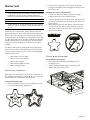
Burner cap placement
Each cap has a letter (B, D, or F) cast in the underside of
the cap that corresponds to a letter (B, D, or F) cast in the
burner base that is attached to the appliance.
To place the burner caps
1. Place each burner cap on its correct burner base per
its corresponding letter designation.
2. Place burner cap gently on top of base so that the
prongs of the burner base fit snugly into the groove of
the burner cap.
Checking the burner cap placement
• Check each burner to make sure there is no gap
between the burner cap and burner base.
• You may gently try to move the burner caps from side
to side to check if the caps are properly placed on the
burner bases.
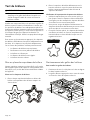
• When properly placed, each burner cap will rest flat
on top of its burner base, and completely cover the
star-shape of the burner base when viewed from the
top as shown below.
Burner grate placement
To install the burner grates
1. Place grates flat-side down and align into the
rangetop recess.
2. Grates should rest flush against each other and
against the sides of the recess.

Page. 17
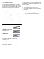
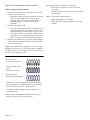
Test rangetop burners
See figures below for appropriate flame characteristics. If
any of the rangetop burners continue to burn mostly or
completely yellow, verify that the burner cap is positioned
properly on the burner base, then re-test. If flame
characteristics do not improve, call Thermador service.
To test burner ignition
1. Select a rangetop burner knob. Push in and turn the
knob to HI.
• The igniter will produce a clicking sound. Once
the air has been purged from the supply lines, the
burner should light within four seconds.
2. Turn burner to LO. Verify that the flame completely
surrounds the burner.
• There should be a flame at each burner port and
there should be no air gap between the flame and
the burner. If any burners do not carry over, call
Thermador service.
3. Repeat the ignition and flame test for each rangetop
burner.
The burners that feature XLO
®
, cause the flame to cycle
on and off when the knob is set to the XLO function. This
is normal operation.
When flame is properly adjusted:
• There should be a flame at each burner port.
• There should be no air gap between the flame and
burner port.
Call Thermador service if:
• Any of the burners do not light.
• Any of the burners continue to burn yellow.
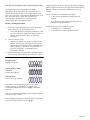
Flame characteristics
Yellow flames:
Further Adjustment is
required.
Yellow tips on outer cones:
Normal for LP Gas
Soft blue flames:
Normal for Natural Gas
If the flame is completely or mostly yellow, verify that
the regulator is set for the correct fuel. After
adjustment, retest.
Some orange-colored streaking is normal during the
initial start-up.
Allow unit to operate 4-5 minutes and re-evaluate
before making adjustments.

Page. 18
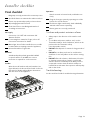
Installer checklist
Final checklist
Gas supply
Electrical
Installer
Operation
To clean and protect exterior surfaces
• Always wipe in the direction of the stainless steel
grain.
• To condition and protect stainless steel, use the
Thermador Stainless Steel Conditioner, which can be
purchased in the Thermador eShop
(store.thermador.com/us).
• DO NOT allow deposits to remain for long periods of
time.
• DO NOT use ordinary steel wool or steel brushes.
Small bits of steel may adhere to the surface causing
rust.
• DO NOT allow salt solutions, disinfectants, bleaches
or cleaning compounds to remain in contact with
stainless steel for extended periods. Many of these
compounds contain chemicals which could prove
harmful. Rinse with water after exposure and wipe dry
with a clean cloth.
Troubleshooting
See Use and Care Guide for troubleshooting information.
Rangetop correctly positioned in countertop recess.
Specified clearances maintained to cabinet surfaces.
Burner caps positioned properly on burner bases.
All packaging material removed.
Flush Island Trim or Low Backguard attached
according to instructions.
Connection: 1/2'' NPT with a minimum 3/4''
diameter flex line.
If converting from natural to LP gas, refer to LP
Conversion Instructions for details.
Manual gas shut off valve installed in an accessible
location (without requiring removal of appliance).
Unit tested and free of gas leaks.
A dedicated polarized and grounded 120VAC
receptacle with a 15/ 20 AMP over current
protection is required for cord connection.
Write the model number and serial numbers (see
figure below) in the Use and Care Guide. Leave the
Use and Care Guide and Installation Instructions
with the owner of the appliance.
Bezels centered on burner knobs, and knobs turn
freely.
Purge air from gas system by operating one of the
burners for several minutes.
Each burner lights satisfactorily, both individually
and with other burners operating.
Burner grates are correctly positioned.
La page est en cours de chargement...
La page est en cours de chargement...
La page est en cours de chargement...
La page est en cours de chargement...
La page est en cours de chargement...
La page est en cours de chargement...
La page est en cours de chargement...
La page est en cours de chargement...
La page est en cours de chargement...
La page est en cours de chargement...
La page est en cours de chargement...
La page est en cours de chargement...
La page est en cours de chargement...
La page est en cours de chargement...
La page est en cours de chargement...
La page est en cours de chargement...
La page est en cours de chargement...
La page est en cours de chargement...
La page est en cours de chargement...
La page est en cours de chargement...
La page est en cours de chargement...
La page est en cours de chargement...
La page est en cours de chargement...
La page est en cours de chargement...
La page est en cours de chargement...
La page est en cours de chargement...
La page est en cours de chargement...
La page est en cours de chargement...
La page est en cours de chargement...
La page est en cours de chargement...
La page est en cours de chargement...
La page est en cours de chargement...
La page est en cours de chargement...
La page est en cours de chargement...
La page est en cours de chargement...
La page est en cours de chargement...
La page est en cours de chargement...
La page est en cours de chargement...
La page est en cours de chargement...
La page est en cours de chargement...
-
 1
1
-
 2
2
-
 3
3
-
 4
4
-
 5
5
-
 6
6
-
 7
7
-
 8
8
-
 9
9
-
 10
10
-
 11
11
-
 12
12
-
 13
13
-
 14
14
-
 15
15
-
 16
16
-
 17
17
-
 18
18
-
 19
19
-
 20
20
-
 21
21
-
 22
22
-
 23
23
-
 24
24
-
 25
25
-
 26
26
-
 27
27
-
 28
28
-
 29
29
-
 30
30
-
 31
31
-
 32
32
-
 33
33
-
 34
34
-
 35
35
-
 36
36
-
 37
37
-
 38
38
-
 39
39
-
 40
40
-
 41
41
-
 42
42
-
 43
43
-
 44
44
-
 45
45
-
 46
46
-
 47
47
-
 48
48
-
 49
49
-
 50
50
-
 51
51
-
 52
52
-
 53
53
-
 54
54
-
 55
55
-
 56
56
-
 57
57
-
 58
58
-
 59
59
-
 60
60


Thermador PCG486WL Guide d'installation
- Taper
- Guide d'installation
dans d''autres langues
- English: Thermador PCG486WL Installation guide
- español: Thermador PCG486WL Guía de instalación
Documents connexes
-
Thermador PCG305P Guide d'installation
-
-
Thermador PCG30 Manuel utilisateur
-
Thermador PRG486WLH Guide d'installation
-
-
Yes 1311253 Guide d'installation
-
Thermador PRG366WG Guide d'installation
-
-
-

