Aruba AP-303H Series Guide d'installation
- Taper
- Guide d'installation

Aruba 303H Series Hospitality Access Point
Installation Guide
0511xxx-01 | November 2016 1
The Aruba AP-303H Series Hospitality Access Points are high-performance dual-radio wireless devices for
hospitality and branch deployments.
These access points use Multiple-Input, Multiple-Output (MIMO) technology to provide secure wireless
connectivity for both 2.4GHz 802.11 b/g/n and 5GHz 802.11 a/n/ac WiFi.
Alternatively, the wired Ethernet ports located on the bottom of this access point allow users to connect directly
to the device when physically linked by an Ethernet cable.
The AP-303H can be attached to a standard single-gang wall box using the mount provided, or converted into a
desk-mounted remote access point for branch office deployments using the AP-303H-MNTW mount kit (sold
separately).
The AP-303H access point provides the following capabilities:
Dual wireless transceivers
IEEE 802.11a/b/g/n/ac operation as a wireless access point
IEEE 802.11a/b/g/n/ac operation as a wireless air monitor
Compatibility with IEEE 802.3af/at PoE
Central management configuration
Supports PoE-in (E0 port)/PoE-out (E3 port)
Support for selected USB peripherals
Integrated Bluetooth Low Energy (BLE) radio
Package Contents
AP-303H Access Point
Single gang wall-box mounting bracket
(2x) #6-32 slotted screws
T8H Torx security screw
Software
The AP-303H access point requires ArubaOS 6.5.2 or higher. For additional information, refer to the ArubaOS User
Guide and ArubaOS Quick Start Guide.
Hardware Overview
The following sections outline the hardware components of the AP-303H access point.
LED
The LED displays located on the front and bottom of the access point indicate the following functions:
Inform your supplier if there are any incorrect, missing, or damaged parts. If possible, retain the carton, including
the original packing materials. Use these materials to repack and return the unit to the supplier if needed.

2 Aruba 303H Series Hospitality Access Point | Installation Guide
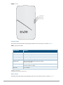
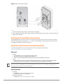
Figure 1 Front
System Status
The System Status LED indicates the operating condition of the access point, as shown in Table 1.
Table 1 System Status LEDs
1 blinking: 1s on/1s off
2 flashing: on/off repeated in less than 1s
Radio Status
The Radio Status LED indicates the operating mode of the access point’s radios, as shown in Table 2.
Color/State Meaning
Off Device is powered off
Green/solid Device is ready; fully functional
Green/blinking
1
Device is booting; not ready
Green/flashing
2
Device is ready; uplink negotiated at suboptimal speed (<1Gbps)
Amber/solid Device is ready; operating in power-save mode
(PoE source: 802.3af).
Amber/flashing Device is ready; operating in power-save mode, with uplink negotiated at
suboptimal speed (<1Gbps)
Red/solid Error condition
PoE-PSE Status
Radio Status
System Status

Aruba 303H Series Hospitality Access Point | Installation Guide 3
Table 2 Radio Status LEDs
Network Status
The Network Status LED, located on the sides of the E1-E3 ports, indicates activity transmitted to/from the wired
ports, as shown in Table 3.
Table 3 Network Status LEDs
PoE-PSE Status
The PoE-PSE LED are located above ports E1-E3, and indicate when the access point is operating as Power
Sourcing Equipment (PSE), providing Power over Ethernet (PoE) to an external device that is physically connected
to the E3 port by Ethernet cable, as shown in Table 4.
Table 4 PoE-PSE Status LEDs
LED Display Settings
The LEDs have three operating modes that can be selected in the system
management software:
Default mode: Refer to Tables 1-3
Off mode: LEDs are off
Color/State Meaning
Off Meets one of the following conditions:
both radios are disabled
device is powered off
Green/solid Both radios enabled in access mode
Green/blinking
1 One radio enabled in access mode; one radio
disabled
Amber/solid Both radios enabled in monitor mode
Amber/flashing Device ready; operating in power-save mode, with uplink negotiated at
suboptimal speed (<1Gbps)
Alternating
3
Error condition
Color/State Meaning
Off Meets one of the following conditions:
device is powered off
port is disabled
no link/activity
Green/solid Link established at max speed (1Gbps)
Green/blinking Activity detected across a max speed link
Amber/solid Link established at reduced speed (10/100Mbps)
Amber/blinking Activity detected across a reduced speed link
Color/State Meaning
Off Access point not supplying PoE, or powered off
Green/solid Access point supplying power to a connected device
Green/blinking Negotiating PoE power supplied to a connected device

4 Aruba 303H Series Hospitality Access Point | Installation Guide
Blink mode: LEDs blink green
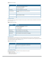
Figure 2
Back Panel
Console Port
The 5-pin USB Micro-B connector located on the back of the access point allows for direct management of the
device when connected to a laptop or serial console. For pin-out details, refer to Figure 3.
Figure 3 Console Port Pin-out
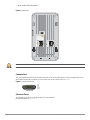
Ethernet Ports
The AP-303H access point is equipped with four active Ethernet
ports (E0-E3). Refer to Figure 4.
E0
57V 600mA
PT
!
The rear panel of the AP-303H may become hot after extended use.
1 2 3 4 5
1: NC
2: RX
3: TX
4: GND
5: GND
USB Micro-B

Aruba 303H Series Hospitality Access Point | Installation Guide 5
Figure 4 Bottom
The E0 port, located at the bottom of the access point is 10/100/1000 Base-T, auto-sensing, MDI/MDX wired-
network uplink connectivity RJ45 port. It supports IEEE 802.3af/802.3at PoE as a standard Powered Device (PD)
from Power Sourcing Equipment (PSE), such as a midspan injector or a network infrastructure that supports PoE.
The E1-E3 ports, located at the bottom of the access point are 10/100/1000 Base-T auto-sensing, MDI/MDX
wired-network downlink connectivity RJ45 ports. These ports are used to provide secure network connectivity to
wired devices when physically linked using an Ethernet cable. Refer to Figure 5 for port pin-out information.
Additionally, the E3 port supports PoE-out functionality, and is capable of supplying up to 13W to PSE when the
access point is operating in 802.3at PoE mode, or powered by a DC source.
Figure 5 Gigabit Ethernet Port Pin-Out
USB Interface
The AP-303H access point is equipped with a USB port that is compatible with cellular modems and Bluetooth
Low Energy (BLE) dongles. When active, the USB port can supply up to 5W/1A to a connected device.
Figure 6 Side
Push Button
The push button located on the right side of the device can be used to reset the access point to factory default
settings or turn off/on the LED display.
To reset the access point to factory default settings:
1. Power off the access point.
2. Press and hold the push button using a small, narrow object, such as a paperclip.
3. Power-on the access point without releasing the push button. The system status LED will flash within 5
seconds.
4. Release the push button.
The system status LED will flash again within 15 seconds indicating that the reset is completed. The access
point will now continue to boot with the factory default settings.
To turn off/on the system status LED:
During the normal operation of the access point, press the push button using a small, narrow object, such as
a paperclip. The system status LED will be turned off/on immediately.
E0
E0 E3E2E1
48V
600mA
AC/DC
power socket
USB port
Reset button
Security Screw Lock

6 Aruba 303H Series Hospitality Access Point | Installation Guide
Power Supply
The AP-303H access point has a single 48V DC power connector to
support AC-to-DC power using an AP-AC-48V36C power adapter (sold separately). The power connector port is
located on the side of the device, as shown in Figure 6.
The AP-303H access point supports both PoE-in and PoE-out functionality.
The PoE-in (PoE-PD) allows the E0 port to draw power from an 802.3at (preferred) source, or an 802.3af
(optional) source.
When powered by an 802.3at or DC power source, the PoE-out (PoE-PSE) functionality is enabled on port E3,
supplying a maximum output of 15W to a wired device.
Refer to Table 4 for power output details. PoE-PSE and USB settings can be enabled/disabled through the
software’s WebUI and CLI.
When both DC and PoE power are simultaneously available, the access point will default to using DC power,
while continuing to draw a minimal current from the PoE source. If DC power source is removed, the access
point will begin drawing power from the PoE source, allowing for a hitless fail-over when switching between
power sources.
Before You Begin
Refer to the sections below before beginning the installation process.
Pre-Installation Checklist
Before installing the AP-303H access point, be sure that you have the following:
Pre-installed wall box
Cat5E UTP cable with network access installed in the wall box
One of the following power sources:
IEEE 802.3af/at-compliant Power over Ethernet (PoE) source
Aruba AP AC-DC adapter kit (sold separately)
One of the following network services:
Aruba Discovery Protocol (ADP)
DNS server with an “A” record
DHCP Server with vendor-specific options
Identifying Specific Installation Locations
When installing the AP-303H access point must be secured to an Aruba-approved wall or to a desk mount kit.
This access point should be oriented vertically, with Ethernet ports facing downward to facilitate maximum
antenna gain. Use the access point placement map generated by Aruba’s RF Plan software application to
determine the proper installation location(s). Each location should be as close as possible to the center of the
intended coverage area and should be free from obstructions or obvious sources of interference. These RF
absorbers/reflectors/interference sources will impact RF propagation and should be accounted for during the
planning phase and adjusted for in RF plan.
Identifying Known RF Absorbers/Reflectors/Interference Sources
Identifying known RF absorbers, reflectors, and interference sources while in the field during the installation
!
This device must be professionally installed and serviced by a trained ACMP or similar Aruba-certified
technician.The installer is responsible for securing the access point onto the ceiling tile rail in accordance with the
steps below. Failure to properly install this product may result in physical injury and/or damage to property.
Tous les points d’accès Aruba doivent être installés professionnellement par un Professionnel en mobilité certifié
par Aruba (ACMP). Il incombe au technicien d’installation de veiller à ce qu’une borne de raccordement à la terre
conforme avec tous les codes électriques nationaux applicables puisse être utilisée.
This device in compliance with governmental requirements, and is designed the so that only authorized network
administrators can change the settings. For more information about access point configuration, refer to the
ArubaOS Quick Start Guide and ArubaOS User Guide.

Aruba 303H Series Hospitality Access Point | Installation Guide 7
phase is critical. Make sure that these sources are taken into consideration when you attach an access point to its
fixed location.
RF absorbers include:
Cement/concrete—Old concrete has high levels of water dissipation, which dries out the concrete, allowing
for potential RF propagation. New concrete has high levels of water concentration in the concrete, blocking
RF signals.
Natural Items—Fish tanks, water fountains, ponds, and trees
Brick
RF reflectors include:
Metal Objects—Metal pans between floors, rebar, fire doors, air conditioning/heating ducts, mesh windows,
blinds, chain link fences (depending on aperture size), refrigerators, racks, shelves, and filing cabinets.
Do not place an access point between two air conditioning/heating ducts. Make sure that access points are
placed below ducts to avoid RF disturbances.
RF interference sources include:
Microwave ovens and other 2.4 or 5 GHz objects (such as cordless phones)
Cordless headset such as those used in call centers or lunch rooms
Installing the Access Point
The AP-303H is designed to mount into a variety of electrical gang boxes.
Use the steps below to install your AP-303H.
1. Begin by removing the existing data wall plate (if applicable).
2. Remove any existing RJ45 connectors (typically snap-in) or cut/remove the UTP cable.
3. Use a short Ethernet cable (sold separately) to connect the E0 port to an RJ45 connector or crimp an RJ45 plug
(not supplied) on the cable and insert in the E0 port. Do the same for the PT port, if used.
4. Align the mounting holes of the AP-303H mounting bracket with mounting holes in you gang box, as shown in
Figure 7 and Figure 8. For worldwide single gang outlet box, the mounting bracket has two sets of mounting
holes to meet the individual installation position requirement.
The applicable standards for the wall boxes are:
IEC 60670-1, GB17466, BS4662 and DIN49073 for Worldwide
ANSI/NEMA OS 1 and OS 2 for US
!
All Aruba access points should be professionally installed by an Aruba Certified Mobility Professional (ACMP).
The installer is responsible for ensuring that grounding is available and meets applicable national and electrical
codes.
Tous les points d'accès Aruba doivent impérativement être installés par un professionnel agréé. Ce dernier doit
s'assurer que l'appareil est mis à la terre et que le circuit de mise à la terre est conforme aux codes électriques
nationaux en vigueur.

8 Aruba 303H Series Hospitality Access Point | Installation Guide
Figure 7 Bracket to Gang Box (US Single Gang Outlet Box Shown)
Figure 8 Bracket to Gang Box (Worldwide Single Gang Outlet Box Shown)
5. Insert the two included machine screws and tighten them to secure the mounting bracket.
6. Connect any required cables to the back of the AP-303H.
7. Align the mounting slots on the back of the AP-303H with the corresponding mounting posts on the wall
mount as shown in Figure 9.
8. Push the access point against the posts and downward until the posts engage the slots at the top of the slots.

Aruba 303H Series Hospitality Access Point | Installation Guide 9
Figure 9 Attaching AP-303H to Bracket
9. Once the access point is fastened onto the wall mount, insert the T8H Torx security screw into the hole
located on the upper-right edge of the wall mount and tighten.
10. If not using PoE, connect the AC-DC power adapter (sold separately) to the DC power socket located on the
bottom of the AP-303H.
Verifying Post-Installation Connectivity
The integrated LED on the Access point can be used to verify that the access point access point is receiving
power and initializing successfully (see Table 1). Refer to the ArubaOS Quick Start Guide for further details on
verifying post-installation network connectivity.
Electrical and Environmental Specifications
For additional specifications on this product, please refer to the product data sheet at
www.arubanetworks.com/safety_addendum.
Electrical
Ethernet:
100/1000 Base-T auto-sensing Ethernet RJ45 interface
IEEE 802.3u (100 Base-T). IEEE 802.3ab (1000 Base-T)
Power over Ethernet IEEE 802.3at 56VDC (nominal) and 802.3af 48VDC (maximum).
Power:
48VDC power interference, support powering through an AC-to-DC power adapter (AP-AC-48V36C)
Maximum power consumption with a full PoE-PSE and USB load: 25W (PoE) or 31W (DC)
Environmental
Operating:
Temperature: 0°C to +40°C (+32°F to +104°F)
Humidity: 5% to 93% non-condensing
Storage and transport:
Temperature: -40°C to +70°C (-40°F to +158°F)
If a power adapter other than the Aruba-approved adapter is used in the US or Canada, it should be NRTL listed,
without an output rated 48VDC, minimum 2A, marked “LPS” and “Class 2”, and suitable for plugging into a
standard power receptacle in the US and Canada.

10 Aruba 303H Series Hospitality Access Point | Installation Guide
Regulatory Information
The regulatory model name for AP-303H/IAP-303H access point is APINH303.
Aruba provides a multi-language document that contains country-specific restrictions and additional safety and
regulatory information for all Aruba access points. This document can be viewed or downloaded at
www.arubanetworks.com.
Medical
1. Equipment not suitable for use in the presence of flammable mixtures.
2. Connect to only IEC 60950-1 or IEC 60601-1 3rd edition certified products and power sources. The end user is
responsible for the resulting medical system complies with the requirements of IEC 60601-1 3rd edition.
3. Wipe with a dry cloth, no additional maintenance required.
4. No serviceable parts, the unit must be sent back to the manufacturer for repair.
5. No modifications are allowed without Aruba approval.
Canada
User manuals for licence-exempt radio apparatus shall contain the following text, or an equivalent notice that
shall be displayed in a conspicuous location, either in the user manual or on the device, or both:
This device complies with Industry Canada’s licence-exempt RSSs. Operation is subject to the following two
conditions:
(1) This device may not cause interference; and
(2) This device must accept any interference, including interference that may cause undesired operation of the
device.
Taiwan
第十二條 → 經型式認證合格之低功率射頻電機,非經許可,公司、商號或使用者均不得擅自變更頻率、加大功率或變更原設計之特性及功能。
第十四條 → 低功率射頻電機之使用不得影響飛航安全及干擾合法通信;經發現有干擾現象時,應立即停用,並改善至無干擾時方得繼續使用。
前項合法通信,指依電信法規定作業之無線電通信。低功率射頻電機須忍受合法通信或工業、科學及醫療用電波輻射性電機設備之干擾。
!
RF Radiation Exposure Statement: This equipment complies with FCC RF radiation exposure limits. This
equipment should be installed and operated with a minimum distance of 10.63 inches (27cm) between the
radiator and your body for 2.4 GHz and 5 GHz operations. This transmitter must not be co-located or operating
in conjunction with any other antenna or transmitter. When operated in 5.15 to 5.25 GHz frequency range, this
device is restricted to indoor use to reduce the potential for harmful interference with co-channel Mobile
Satellite Systems.
!
Déclaration sur les limites d'exposition aux radiofréquences :cet équipement est conforme aux limites
d'exposition aux rayonnements radioélectriques spécifiées par la FCC. Il doit être installé et utilisé à une distance
minimale de 27 cm par rapport à votre corps pour les fréquences de 2,4 et 5 GHz. Cet émetteur-récepteur ne
doit pas être utilisé ou situé à proximité d'autres antennes ou émetteurs-récepteurs. En cas d'utilisation dans la
plage de fréquences de 5,15 à 5,25 GHz, cet appareil doit uniquement être utilisé en intérieur afin de réduire les
risques d'interférence avec les systèmes satellites mobiles partageant le même canal.
Expected Service Life 10 years. For additional compliance information, refer to the label on the side of this
device.
!
Changes or modifications to this unit not expressly approved by the party responsible for compliance could void
the user’s authority to operate this equipment.
Toute modification effectuée sur cet équipement sans l'autorisation expresse de la partie responsable de la
conformité est susceptible d'annuler son droit d'utilisation.

© Copyright 2017 Hewlett Packard Enterprise Development LP
www.arubanetworks.com
1344 Crossman Avenue
Sunnyvale, California 94089
Phone: 408.227.4500
Fax: 408.227.4550
a Hewlett Packard
Enterprise company
11 Aruba 303H Series Hospitality Access Point | Installation Guide
Proper Disposal of Aruba Equipment
Dispose of Aruba products per local regulation. For the most current information about Global Environmental
Compliance and Aruba products, see our website at www.arubanetworks.com.
-
 1
1
-
 2
2
-
 3
3
-
 4
4
-
 5
5
-
 6
6
-
 7
7
-
 8
8
-
 9
9
-
 10
10
-
 11
11


Aruba AP-303H Series Guide d'installation
- Taper
- Guide d'installation
dans d''autres langues
Documents connexes
-
Aruba AP-303H Guide d'installation
-
Aruba 207 Series Guide d'installation
-
Aruba Instant On AP25 Mode d'emploi
-
Aruba 630 series Guide d'installation
-
Aruba 500R Series Remote Access Points Guide d'installation
-
-
Aruba AP-515 Guide d'installation
-
Autres documents
-
Dell W-IAP92/93 Mode d'emploi
-
Samsung WEA412h Manuel utilisateur
-
Dell W-Series 205H Access Points Le manuel du propriétaire
-
Dell W-Series 334/335 Access Points Le manuel du propriétaire
-
Dell W-Series 324/325 Access Points Le manuel du propriétaire
-
Aruba Networks AP-214 Guide d'installation
-
-
Dell W-Series 228 Access Points Le manuel du propriétaire
-
CAME XNS08P Guide d'installation
-
Valcom VL550F Guide d'installation