
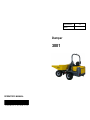
Dumper
3001
OPERATOR’S MANUAL
1000185002 3.2
0608
1000185002

BA 3001 US – Edition 3.2 * 345001b110.fm 1-1
Introduction
1 Introduction
1.1 Important information on this Operator's Manual
Please store the Operator's Manual in the storage bin under the engine cover.
This Operator's Manual contains important information on how to work safely, correctly
and economically with the machine. Therefore, it aims not only at new operators, but it also
serves as a reference for experienced ones. It helps to avoid dangerous situations and
reduce repair costs and downtimes. Furthermore, the reliability and the service life of the
machine will be increased by following the instructions in the Operator's Manual. This is
why the Operator's Manual must always be kept at hand on the machine.
Your own safety, as well as the safety of others, depends to a great extent on how the
machine is moved and operated. Therefore, carefully read and understand this Operator's
Manual prior to the first drive. This Operator's Manual will help to familiarize yourself more
easily with the machine, thereby enabling you to use it more safely and efficiently.
Prior to the first drive, carefully read chapter “Safety Instructions” as well, in order to be
prepared for possible dangerous situations, as it will be too late for it during operation. As a
rule, keep the following in mind:
Careful and prudent working is the best way to avoid accidents!
Operational safety and readiness of the machine do not only depend on your skill, but also
on maintenance and servicing of the machine. This is why regular maintenance and
service work is absolutely necessary. Extensive maintenance and repair work must always
be carried out by an expert with appropriate training. Insist on using original spare parts
when carrying out maintenance and repair work. This ensures operational safety and
readiness of your machine, and maintains its value.
Your Wacker Neuson dealer will be pleased to answer any further questions regarding the
machine or the Operator's Manual.
Abbreviations / symbols
• This symbol stands for a list
• Subdivision within lists or an activity. Follow the steps in the recommended sequence
☞This symbol requires you to carry out the activity described
➥Description of the effects or results of an activity
n. s. = not shown
“Opt” = option Stated whenever controls or other components of the machine are installed
as an option.

1-2 BA 3001 US – Edition 3.2 * * 345001b110.fm
Introduction
1.2 Brief description
The model 3001 dumper is a self-propelled work machine.
Get informed on and follow the legal regulations of your country.
This machine is a versatile and powerful helper for moving earth, gravel and debris on
construction sites and elsewhere. The main components of the machine are:
• Rollbar
• Hydraulic swivel dump bucket or front dump bucket
• Yanmar three cylinder diesel engine
• Sturdy steel sheet chassis
1.3 Operator qualifications
Requirements to be met by the operator
Earth moving machines may be driven and serviced only by persons who meet the
following requirements:
• 18 years or older
• Physically and mentally suited for this work
• Persons have been instructed in driving and servicing the earth moving machine and
have proven their qualifications to the contractor
• Persons are expected to carry out work reliably.
They have been appointed by the contractor for driving and servicing the earth moving
machine.
Get informed on and follow the legal regulations of your country.

BA 3001 US – Edition 3.2 * 345001b110.fm 1-3
Introduction
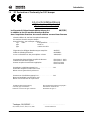
1.4 EC Declaration of Conformity for 3001 dumper
EG-Konformitätserklärung
EC-Declaration of Conformity
Déclaration de conformité
im Sinne der EG-Maschinenrichtlinie Anhang II A 98/37/EC,
in addition to the EC machine directives
Annex
dans l’esprit des directives du conseil relatives aux machines
Annexe
Hiermit erklären wir, daß der Kompakt-Allraddumper
We declare, that the compact-dumper
Nous déclarons, que le dumper compact
Typ 3001 Fahrgestell-Nr. ......................
type serial-no.
type numéra de série.
folgenden einschlägigen Bestimmungen entspricht: 98/37/EC
fulfills the
following directives:
89/336EEC
est en conformité avec des prescriptions suivant:
2000/14/EC
Angewendete harmonisierte europäische Normen EN 12100-1 : 2003
Harmonized standards applied
EN 12100-2 : 2003
Normes euopéen harmonisées appliquées
EN 474-1 1994
EN 474-6 1996
Garantierter Schalleistungspegel L
WA . . . . . . . . . . . . . . . . . . . . . . . . . . .
101
Guarantee weighted Sound Power Level
Niveau sonore garanti de la puissance
Gemessener Schallleistungspegel L
WA . . . . . . . . . . . . . . . . . . . . . . . . .
101
Measured weighted Sound Power Level
Niveau sonore mesuré de la puissance
Freiwilligen Baumusterprüfung: Baumusterprüfungsbescheinigung-Nr.:
Voluntary type-examination Eximination certificate No.:
Effectuer l´examen de type volontaire Attestation de type n°:
........................................................ .........................................................
Ort, Datum / Place, date / Lieu, date Technical Director
Tredegar, 18/12/2007

1-4 BA 3001 US – Edition 3.2 * * 345001b110.fm
Introduction
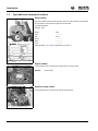
1.5 Type labels and component numbers
Serial number
The serial number is stamped on the machine chassis. It is also located on the type label.
The type label is located at the rear right of the control stand.
Type label information
Example: 3001
Model: 3001
Year: ---------------
PIN: AE 31....
Power: ---------------
Mass: ---------------
Load: ---------------
Other information – see chapter 6 Specifications on page 6-1
Engine number
The type label (arrow) is located on the cylinder-head cover of the engine.
Example: Yanmar 46557
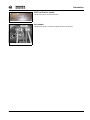
Hydraulic pump number
The type label (arrow) is located on the hydraulic pump housing.
Fig. 1: Type label: location
Fig. 2: Type label
Fig. 3: Yanmar diesel engine number
Fig. 4: Number of variable displacement pump

BA 3001 US – Edition 3.2 * 345001b110.fm 1-5
Introduction
ROPS certification number
The label is located on the left on the ROPS.
Axle number
The type label (arrow) is located on the upper side of the axle housing.
Fig. 5: ROPS type label
Fig. 6: Axle type label

1-6 BA 3001 US – Edition 3.2 * * 345001b110.fm
Introduction
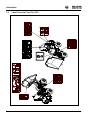
1.6 Label Overview Front Tip 3001

BA 3001 US – Edition 3.2 * 345001b110.fm 1-7
Introduction
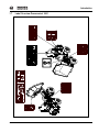
1.7 Label Overview Powerswivel 3001

1-8 BA 3001 US – Edition 3.2 * * 345001b110.fm
Introduction
1.8 Symbol descriptions
The following symbols are displayed on the machine to provide pictorial information to the
user. The information and explanations are provided to avoid misinterpretation by the user.
The symbols have been chosen to provide important information to those involved with
operating, adjusting, maintaining, and repairing this machine.
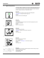
Description
Lift the machine or machine parts only by means of these lifting points.
– see chapter 3.19 Lifting the machine on page 3-28
Location
On the rear chassis next to the lifting point
Description
Tie down points.
Location points designated for tie down of the machine during transport to prevent
movement during transport.
Location
In the ner of the dump bucket
Description
Loading indications for machine.
– see chapter Strapping down the machine on page 3-30
Location
On the engine cover
Description
Noise levels produced by the machine.
L
WA
= sound power level
Other information – see chapter 6.11 Noise levels on page 6-4
Location
On the engine cover
Description
This label indicates the maximum authorized angle of inclination for driving on slopes,
whatever the position of the machine.
Location 3001 Front Tip
On the dump bucket
Fig. 7: Eye hook label
Fig. 8: Label for points used for strapping down the
machine
KRRNRIFUDQH
.UDQKDNHQ
&URFKHWGHJUXH
%JHO
KDQGOH
(WULHU
+HEHEDQG
(OLQJXHHQUXEDQ
OLIWLQJEHOW
(LOOHWRQGHOHYDJH
VWRSH\H
+XE|VH
.QLFNVSHUUHHLQOHJHQ
IDVWHQDUWLFXODWLRQUHVLVWDQFH
$SSOLTXHUOHGLVSRVLWLIGHEORFDJHGHODUWLFXODWLRQ
Fig. 9: Label with indications for loading the machine
Fig. 10: Noise level label
Fig. 11: Driving on slopes Front Tip

BA 3001 US – Edition 3.2 * 345001b110.fm 1-9
Introduction
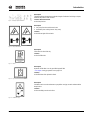
Description
This label indicates the maximum authorized angle of inclination for driving on slopes,
whatever the position of the machine.
Location 3001 Powerswivel
On the dump bucket
Description
1. Stay away from the machine work area.
2. Articulation joint crushing hazard. Stay away!
Location
On the left and right of front chassis
Description
Fill location for diesel fuel only.
Location
On the fuel filler inlet
Description
Hydraulic oil filler inlet. Use only specified hydraulic fluid.
– see chapter Filling up hydraulic oil on page 5-19
Location
On the filler inlet of the hydraulic oil tank
Description
Fold down and secure the maintenance prop before carrying out work underneath the
dump bucket.
Location
On the swivelling console at the front
Fig. 12: Driving on slopes Powerswivel
Fig. 13: Keep a safe distance
Fig. 14: Diesel
Fig. 15: Hydraulic oil
Fig. 16: Maintenance prop

1-10 BA 3001 US – Edition 3.2 * * 345001b110.fm
Introduction
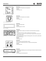
Description
Shows how the dump bucket can be dumped out.
Location
On the engine cover
Description
Shows how the dump bucket can be swivelled.
Location
On the engine cover
Description
Machine serial number label
Location
At the front right of the chassis
Description
1. Attention! Remove starter key and read the Service Manual before servicing the
machine.
2. Hot surface! Do not touch. Keep a safe distance from the machine.
3. Cutting hazard. Cooling fan can cut when rotating. Stop engine before working on the
engine or cooling system.
4. Crushing hazard. Place safety strut in blocking position on the hydraulic cylinder before
performing maintenance.
Location
On the engine cover
Description
Always fasten the seat belt if the rollbar is raised!
Do not use the seat belt when the ROPS is lowered to the stored position.
Location
On the engine cover
Description
Recommended tire inflation pressure. Read the Operator’s Manual for detailed instructions
and load ratings.
Location
On the mudguards and the dump bucke
Fig. 17: Dumping out the dump bucket
Fig. 18: Swivelling the dump bucket
Fig. 19: Serial number
Fig. 20: Caution
Fig. 21: Lap belt
Fig. 22: Tire pressure
-
 1
1
-
 2
2
-
 3
3
-
 4
4
-
 5
5
-
 6
6
-
 7
7
-
 8
8
-
 9
9
-
 10
10
-
 11
11


