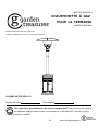
Garden Treasures PG183H Guide d'installation
- Taper
- Guide d'installation

1
Garden Treasures® is a registered trademark
of LF, LLC. All Rights Reserved.
ATTACH YOUR RECEIPT HERE
Serial Number Purchase Date
Questions, problems, missing parts? Before returning to your retailer, call our customer
service department at 1-800-643-0067, 8 a.m. - 8 p.m., EST, Monday - Friday.
ITEM #0749293
GAS PATIO HEATER
MODEL #PG183H
Français p. 18
Español p. 35
AB15632

2
TABLE OF CONTENTS
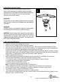
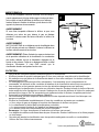
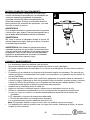
FOR YOUR SAFETY
If you smell gas:
1. Shut off gas to the appliance.
2. Extinguish any open flame.
3. If odor continues, keep away from the
appliance and immediately call your
gas supplier or fire department.
Do not store or use gasoline or other
flammable vapors and liquids in the
vicinity of this or any other appliance.
An LP-cylinder not connected for use
shall not be stored in the vicinity of this
or any other appliance.
For Outdoor Use Only
Improper installation, adjustment,
alteration, service or maintenance can
cause property damage, injury or death.
Read the installation, operation and
maintenance instructions thoroughly
before installing or servicing this
equipment.
Product Specifications««..............3
Package Contents««..............4
Hardware Contents««.................5
Preparation«««««.......................................................................................................5
Safety Information««.............6
Assembly Instructions««..........................................................8
Operating Instructions««....................12
Care and Maintenance««.....................14
Troubleshooting««..............16
Warranty««........................................................................................................................16
Replacement Parts List««.......17
DANGER
WARNING: WARNING
WARNING

3
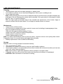
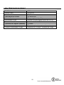
PRODUCT SPECIFICATIONS
Certification CSA
Height Overall 86.6 in.
Reflector Diameter 31.5 in.
Rated Heat Input 47,000 BTU/HR
Fuel Propane-LP
Gas Supply 20-lb. LP-Gas Cylinder
Manifold Pressure 11 in. W.C.
Injector Size (Diameter) 2.14 mm
Safety Features Thermocouple & Tilt Switch
Gas Supply Pressure Max 150 PSI, Min 5 PSI

4
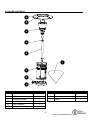
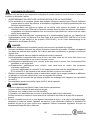
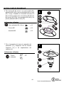
PACKAGE CONTENTS
PART DESCRIPTION QUANTITY PART DESCRIPTION QUANTITY
A Top Dome 1 G Wheel Assembly 1
B KD Dome 4 H Base 1
C Burner Assembly 1 I Cover 1
D Deck Ring 1
E Pole Assembly 1
F Cylinder Assembly 1
G
A
B
C
D
E
F
H
I

5
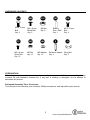
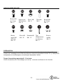
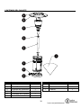
HARDWARE CONTENTS
PREPARATION
Before beginning assembly of product, make sure all parts are present. Compare parts with package
contents list and hardware contents list. If any part is missing or damaged, do not attempt to
assemble the product.
Estimated Assembly Time: 30 minutes.
Tools Required for Assembly (not included): Phillips screwdriver and adjustable open wrench.
M8 x 15 mm
Bolt
Qty. 2
M5 x 8 mm
Black Bolt
Qty. 5
M8 Nut
Qty. 2
Battery
Size ³AAA´
Qty. 1
M6 x 10 mm
Bolt
Qty. 4
M5 x 8 mm
Silver Bolt
Qt
y
. 15
M5 Nut
Qty. 12
M5 Washer
Qty. 12
Reflector Spacer
Qty. 3
Wing Nut
Qty. 3
AA BB EE
FF
CC
HH IIGG JJ
DD

6
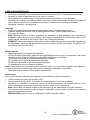
SAFETY INFORMATION
Please read and understand this entire manual before attempting to assemble, operate or install the
product.
z CALIFORNIA PROPOSITION 65 WARNING:
(a) Chemicals known to the state of California to cause cancer, birth defects or other
reproductive harm are created by combustion of propane.
(b) Handling the brass material on this product exposes you to lead, a chemical known to the
state of California to cause cancer and birth defects or other reproductive harm. Wash hands
after handling.
z The installation must conform with local codes or, in the absence of local codes, with the
National Fuel Gas Code, ANSI Z223.1/NFPA 54, Natural Gas and Propane Installation Code,
CSA B149.1, or Propane Storage and Handling Code, B149.2.
DANGER
z Young children should be carefully supervised when they are in the area of the item.
z Keep the ventilation opening(s) of the cylinder enclosure free and clear from debris. Use this
appliance in a well-ventilated space only. Do not use it in a building, garage or any other
enclosed area.
z Use this appliance in outdoor areas described below:
(a) With walls on all sides, but at least one permanent opening at ground level and no overhead
cover.
(b) Within a partial enclosure that includes overhead cover and no more than two walls. These
walls may be parallel or at right angles to each other.
(c) Within a partial enclosure that includes overhead cover and no more than two walls. The
following shall apply:
(i) One wall that is equivalent to at least 25% of the total wall area is completely open.
(ii) 30% or more in total of the remaining wall area is open and unrestricted.
z Store the cylinder outdoors in a well-ventilated area (not in a building, garage, or other enclosed
area) out of the reach of children.
z Do not store a spare LP-gas cylinder under or near this appliance.
z Never fill the cylinder beyond 80 percent full.
WARNING
z Perform a leak test with a soapy solution:
(a) To check gas connections.
(b) After connecting a new cylinder.
(c) Upon re-assembly after disassembly.
Please refer to the leak test procedure indicated in this instruction manual on page 12.
z Replace the hose assembly prior to the appliance being put into operation if there is evidence of
excessive abrasion or wear, or if the hose is damaged. The pressure regulator and hose
assembly supplied with the appliance must be used. The replacement hose assembly/regulator
shall be that specified by the manufacturer.

7
SAFETY INFORMATION
z Place the propane hose with regulator assembly out of pathways where people may trip over it or
in areas where the hose will not be subjected to accidental damage.
z The cylinder used must include a collar to protect the cylinder valve.
z Installation and repair should be done by a qualified service person; the heater should be
inspected before use and at least annually by a qualified service person.
z Do not obstruct the flow of combustion and ventilation air.
z The LP-gas supply cylinder to be used must be:
(a) Constructed and marked in accordance with the Specifications for LP-gas cylinders of the
U.S. Department of Transportation of Dangerous Goods and Commission, CAN/CSA-B339,
as applicable;
(b) Provided with a listed overfilling prevention device; and
(c) Provided with a cylinder connection device compatible with the connection for the appliance.
z Disconnect the cylinder when the appliance is not in use.
z Storage of an appliance indoors is permissible only if the cylinder is disconnected and removed
from the appliance.
z Materials or items when stored under the heater will be subjected to intense heat and could be
seriously damaged.
z Clothing or other flammable materials should not be hung on the heater, or placed on, under or
near the heater.
z Children and adults should be alerted to the hazards of high surface temperatures and should
stay away from the item to avoid burns or clothing ignition.
z Place the dust cap tightly on the cylinder valve outlet whenever the cylinder is not in use. Install
only the type of dust cap on the cylinder valve that is provided with the cylinder valve. Other
types of caps or plugs may result in a propane leak.
CAUTION
z Minimum clearance to the combustible materials is 44 in.
z ,I\RXGRQ¶WIHHOWKHKHDWHULVRQDVWDEOHVXUIDFHXVHDJURXQGVFUHZWRIL[ the base of the heater
on the surface where the heater is installed. Fix the base on an incline no wider than 15 degrees.
z This heater is equipped with a battery-operated ignition device; please refer to the Assembly
Instructions on page 12.
z Any guard or other protective device removed for servicing the heater must be replaced prior to
operating the heater.
z More frequent cleaning may be required as necessary. It is imperative that the control
compartment, burners and circulating air passageways of the heater to kept clean.
z Keep the appliance area clear and free from combustible materials, gasoline and other
flammable vapors and liquids.
g Inspect the visible portion of the hose before each use of the appliance. When portions of the
hose are located within the confines of the heater post, instructions to inspect the entire hose
assembly at least annually. If disassembly is required, the instructions shall also include the
proper procedure for leak checking the connections upon re-assembly.
z More frequent cleaning may be required as necessary. It is imperative the control compartment,
burners and circulating air passageways of the heater are kept clean.
z Keep this manual for future reference and to educate new users of this product.

8
ASSEMBLY INSTRUCTIONS
Hardware Used
Hardware Used
Hardware Used
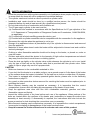
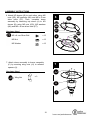
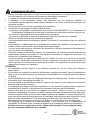
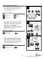
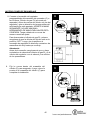
1. With the base (H) upside down, attach
wheel assembly (G) using M8 x 15 mm
bolts (AA) and M8 nuts (CC).
2. Turn the base (H) right-side up, then attach
cylinder assembly (F) using M5 x 8 mm
black bolts (BB) though preassembled
L-pins.
Note: The door on the cylinder assembly
(F) should be on the opposite side of the
wheel assembly (G).
3. Attach pole assembly (E) to cylinder
assembly (F) using M6 x 10 mm bolts (EE).
Note: Ensure the pole assembly (E) is
straight. Then, use deck ring (D) to cover
connection.
1
2
X 2
X 2
M8 Nut
M8X15mm Bolt
AA
CC
M8 x 15 mm Bolt
M8 Nut
x 2
x 2
X
5
BB
M5 X 8mm Bolt
M5 x 8 mm Black Bolt
x 5
3
H
CC
AA
G
FH
G
BB
D
E
F
EE
M6 X 10 mm Bolt
X 4
M6 x 10 mm Bolt x 4
Door
Back

9
ASSEMBLY INSTRUCTIONS
Hardware Used
Hardware Used
5
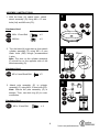
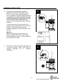
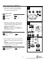
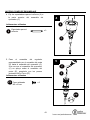
5. Thread the regulator assembly
preassembled to burner assembly (C)
through the pole assembly (E). Once the
burner assembly (C) rests on pole
assembly (E), secure with M5 x 8 mm
silver bolts (FF).
4. Insert reflector spacers (II) into the top
of burner assembly (C).
4
II
C
C
E
FF
x3
Reflector Spacer
II
Reflector Spacer
x 3
X 3
M5 X 8 mm Silver Bolt
FF
M5 x 8 mm Silver Bolt
x 3

10
ASSEMBLY INSTRUCTIONS
Hardware Used
Hardware Used
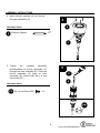
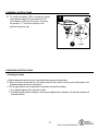
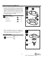
6. Attach KD domes (B) to each other using M5
nuts (GG), M5 washers (HH) and M5 x 8 mm
silver bolts (FF). Then, complete dome
assembly by attaching top dome (A) to KD
domes (B) using M5 nuts (GG), M5 washers
(HH) and M5 x 8 mm silver bolts (FF).
7. Attach dome assembly to burner assembly
(C) by securing wing nuts (JJ) to reflector
spacers (II).
6
7
B
GG
HH
FF
GG
FF
A
JJ
II
C
X
3
Wing Nut
JJ
FF
HH
GG
X 12
5 mm Washer
X 12
M5 X 8 mm Silver Bolt
X 12
M5 Nut
M5 x 8 mm Silver Bolt
M5 Nut
M5 Washer
x 12
x 12
x 12
Wing Nut
x 3

11
ASSEMBLY INSTRUCTIONS
9
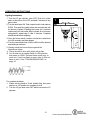
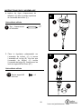
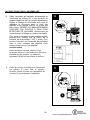
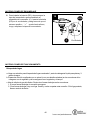
9. Attach strap inside of cylinder assembly (F)
to secure cylinder. Then, close door on
cylinder assembly (F) to complete
installation.
8. Connect the preassembled regulator
assembly from burner assembly (C) to a
20-lb. LP-gas cylinder (sold separately).
Line up threads on cylinder fitting with those
on regulator and rotate clockwise until tight.
HAND TIGHTEN ONLY. DO NOT USE ANY HAND
TOOLS TO MAKE THIS CONNECTION. Be
careful not to cross threads when screwing
in fitting.
To disconnect the LP-gas cylinder, first
make sure the cylinder valve is in the "OFF"
position. Then, turn the knob on the
regulator assembly counterclockwise until it
is loose.
Warning
Before connecting, be sure there is no
debris caught in the head of the LP-gas
cylinder regulator valve or in the head of the
burner and burner ports.
8
F

12
ASSEMBLY INSTRUCTIONS
OPERATING INSTRUCTIONS
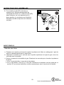
10. To install the battery (DD), unscrew the igniter
cap preassembled to burner assembly (C).
Insert battery (DD) into the igniter, ensuring
the positive "+" end faces outward, then
replace the igniter cap.
10
Checking for Leaks
a. Make leakage solution by mixing 1-part liquid dish soap and 3-parts water.
b. Spoon or brush several drops (or use squirt bottle) of the solution onto the gas hose/regulator and
regulator/cylinder and hose connections.
c. Turn on gas cylinder valve. Inspect the connections and look for bubbles.
1. If no bubbles appear, the connection is safe.
2. If bubbles appear, there is leakage. Loosen and re-tighten this connection. If it still leaks, please call
customer service.
C
Igniter
+
-

13
OPERATING INSTRUCTIONS
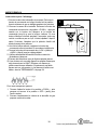
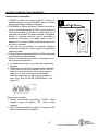
Lighting Instructions
1
1. Turn the LP gas cylinder valve OFF. Push the control
knob on the pole in, turn OFF, and wait 5 minutes for any
gas to clear.
2. Turn the tank valve ON. Push control knob in and rotate to
PUSH. Then push the igniter button and control knob until
the burner is ignited. If igniting the burner for 5 seconds
continuously but the burner fails to remain lit or becomes
extinguished, repeat step 2 after 5 minutes. Complete
shutoff period before relighting.
3. Once the burner has lit, continue to hold the control knob
in for 30 seconds, and then release.
4. Turn the control knob from LOW to HIGH until the desired
heat setting is achieved.
5. Visually check the burner flame against the
illustrations below:
1) Flame should be blue with slight yellow tips.
2) You should see a smaller flame in LOW position
than seen on HIGH. Perform flame check prior to
HDFKXVH,IRQO\ORZIODPHLVVHHQUHIHUWR³%XUner
IODPHLVORZ´LQWKH ³TROUBLESHOOTING´on
page 16.
For complete shutdown
1. Please tXUQWKHNQREWR³Push´position first, then push
DQGWXUQWR³2II´SRVLWLRQIRUFRPSOHWHVKXWRII
2. Turn the LP gas tank valve OFF before remove the LP
gas tank.
Igniter
push
HIGH
LOW
PUSH
OFF

14
OPERATING INSTRUCTIONS
0
CARE AND MAINTENANCE
z Abrasive cleaners will damage this product.
z Never use oven cleaner to clean any part of heater
z Do not clean any heater part in a self-cleaning oven. The extreme heat will damage the finish.
z More frequent cleaning may be required as necessary. It is imperative that control compartment,
burners and circulating air passageways of the heater be kept clean.
z Spiders and insects can create a dangerous condition that may damage heater or make it unsafe.
Keep burner area clean of all spiders, webs or insects. Clean burner holes by using a heavy-duty
pipe cleaner. Compressed air may help clear away smaller particles.
z Inspect heater before each use.
z Have heater inspected annually and repairs should be made by a qualified service person.
z Check heater immediately if any of the following conditions exist:
a. The smell of gas in conjunction with extreme yellow tipping of burner flames.
b. Heater does not reach proper temperature.
F+HDWHU¶VJORZLVH[FHVVLYHO\XQHYHQ
d. Burner makes popping noises during use.
Note: A slight pop is normal when burner is extinguished.
z Carbon deposits may create a fire hazard. Keep dome and emitter clean at all times.
z Do not clean heater with combustible or corrosive cleaners. Use warm, soapy water.
z Do not paint engine, engine access panel or dome.
z This heater should be thoroughly cleaned on a regular basis.
z After a period of storage and/or non use, check for leaks, burner obstructions and inspect for any
abrasion, wear, cuts to the hose.
In any case of failure of normal ignition, please use the
lighter (sold separately) to reach the burner for ignition
through the hole on the bottom of burner diffuser. Insert the
lighter from the back side of the burner assembly
opposite to the control panel.
WARNING
If at any time you are unable to light burner and smell gas,
wait 5 minutes to allow gas to dissipate before attempting to
light heater.
WARNING
DO NOT touch or move heater for at least 45 minutes after
use. Allow emitter and dome to cool before touching.
WARNING: Avoid inhaling fumes emittHGIURPWKHKHDWHU¶V
first use. Smoke and odor from the burning of oils used in
manufacturing will appear. Both smoke and odor will
dissipate after approximately 30 minutes. The heater should
NOT produce thick black smoke.
2

15
CARE AND MAINTENANCE
Cleaning
z Wipe surfaces clean with mild dish detergent or baking soda.
z For stubborn surfaces use a citrus-based degreaser and a nylon scrubbing brush.
z Rinse clean with water.
Note: While cleaning the unit, be sure to keep the area around the burner and pilot assembly dry
at all times. Do not submerge the control valve assembly. If the gas control is submerged in water,
do NOT use it. It must be replaced.
TIP: Use high-quality automobile wax to help maintain the appearance of the heater. Apply to
exterior surfaces from the pole down. Do not apply to emitter screen or domes
Maintenance
z Keep exterior surfaces clean.
z Air flow must be unobstructed. Keep controls, burner and circulating air passageways clean.
Signs of possible blockage include:
Gas odor with extreme yellow tipping of flame.
Heater does NOT reach the desired temperature.
Heater glow is excessively uneven.
Heater makes popping noises.
Note: In a salt-air environment (such as near an ocean), corrosion occurs more quickly than normal.
Frequently check for corroded areas and repair them promptly.
z Battery replacement: Use an alkaline AAA battery.
Storage
Between uses or during periods of extended inactivity:
z Turn control knob to "OFF".
z Disconnect LP cylinder and move to a secure, well-location outdoors.
z Store heater upright in an area sheltered from direct contact with inclement weather (such as rain,
sleet, hail, snow, dust and debris).
Note: Never leave LP gas tank exposed to direct sunlight or excessive heat.
z If desired, use cover (I) to protect the heater and help prevent buildup in air passages.
CAUTION: Wait until heater is cool before covering.

16
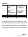
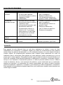
TROUBLESHOOTING
PROBLEM POSSIBLE CAUSE
CORRECTIVE ACTION
Burner doesn¶t light 1. Gas pressure is low.
2. The orifice is blocked.
3. &RQWURONQRELVQRWLQ³PUSH´
position.
1. Turn the gas cylinder YDOYH³2))´
and replace the cylinder.
2. Clear blockage.
3. 7XUQFRQWURONQREWR³PUSH´
position.
Burner flame is low 1. Gas pressure is low.
2. The control knob is not
SRVLWLRQHGDW³+LJK´
3. The burner jet is partially
blocked.
4. Outdoor temperature is less
than 40°F and tank is less
than 1/4 full.
5. Supply hose is bent or kinked.
1. Turn the gas cylinder YDOYH³2))´
and replace the cylinder.
2. 3RVLWLRQWKHFRQWURONQREDW³+LJK´
3. Clear blockage.
4. Use a full gas cylinder.
5. Straighten the hose.
Carbon buildup Seasonal accumulation.
Wipe off before lighting.
Thick black smoke Blockage in burner.
Remove blockage and clean burner
inside and outside.
WARRANTY
The appliance has been manufactured under the highest standards of quality and workmanship. We
warrant to the original consumer/purchaser that all aspects of this product will be free of defects in
material and workmanship for one (1) year from the date of purchase. Replacements for any
defective part will be supplied free of charge for installation by the consumer. Defects or damage
caused by the use of other than genuine parts are not covered by this warranty. This warranty shall
EHHIIHFWLYHIURPWKHGDWHRISXUFKDVHDVVKRZQLQWKHSXUFKDVHU¶VUHFHLSW7KLVZDUUDQW\LVYDOLGIRU
the original consumer purchaser only and excludes industrial, commercial or business use of the
product, product damage due to shipment or failure which results from alteration, product abuse or
product misuse, where performed by a container, service company or consumer. We will not be
responsible for labor charges and/or damage incurred in installation, repair or replacement, nor for
incidental or consequential damage. This warranty gives you specific legal rights, and you may also
have the other rights that vary from state to state.

17
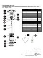
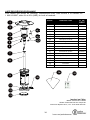
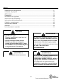
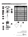
REPLACEMENT PARTS LIST
For replacement parts, call our customer service department at 1-800-643-0067, 8 a.m. - 8 p.m.,
EST, Monday ± Friday.
PART DESCRIPTION
PART #
1 Top Dome
5007755
2 KD Dome
5007756
3 Burner Chamber Assembly
5207453
4 Burner Assembly
0749293-4
4.1
Thermocouple
2409043
4.2
Ignition Pin
2409604
4.3 Tilt Switch
2310662
5
Knob
2100462
6
Igniter
2408276
7 Deck Ring
5201949
8 Pole Assembly
5207459
9 Cylinder Assembly
0749293-9
10 Wheel Support
0749293-10
11 Shroud Fix Bracket
5203158
12 Base
5206378
13 Weight Plate
2307153
14 Cover
3106103
15 Hardware Pack
5207466
Printed in China
Master contract NO.:219529
Garden Treasures® is a registered trademark
of LF, LLC. All Rights Reserved.
C2
C3
C6
C5
C4
C1
K
H
F
G
B
A
C
E
D
L
L
GG
M5 Nut (x12)
HARDWARE Model No. : PG183H
M5 X 8mm Silver Bolt (x12)
5 mm Washer
(x12)
Reflector Spacer (x3)
M8 X 15mm Bolt (x2)
M5 Nut (x12)
M8 Nut (x2)
M6 X 15mm Bolt (x3)
M5 X 8mm Black Bolt (x6)
Wing Nut (x3)
FF
HH
BB
AA
DD
KK
CC
EE
GG
I

18
Garden Treasures® est une marque de
commerce déposée de LF, LLC. Tous droits réservés.
JOIGNEZ VOTRE REÇU ICI
Numéro de série 'DWHG¶DFKDW
Des questions, des problèmes, des pièces manquantes? $YDQWGHUHWRXUQHUO¶DUWLFOH
au détaillant, appelez notre service à la clientèle au 1 800 643-0067, entre 8 h et 20 h
(HNE), du lundi au vendredi.
ARTICLE #0749293
CHAUFFERETTE À GAZ
POUR LA TERRASSE
MODÈLE #PG183H

19
TABLE DES MATIÈRES
POUR VOTRE SÉCURITÉ
Si vous sentez une odeur de gaz :
1. Coupez l¶DOLPHQWDWLRQHQgaz de
O¶DSSDUHLO
2. Éteignez toute flamme nue.
3. 6LO¶RGHXUSHUVLVWHtenez-vous à
GLVWDQFHGHO¶DSSDUHLOHWDSSHOH]
immédiatement votre fournisseur de
gaz RXOHVHUYLFHG¶LQFHQGLH
Ne stockez pas HW Q¶XWLOLVH] SDV
G¶HVVHQFH QL WRXWH DXWUH YDSHXU RX
liquide inflammable à proximité de cet
appareil ou de tout autre appareil.
Aucune bouteille de gaz de pétrole
liquéfié non utilisée ne doit être rangée à
proximité de cet appareil ou de tout autre
appreil.
3RXUXVDJHjO¶H[Wérieur seulement
Une installation, un réglage, une
modification, une utilisation ou un
entretien inadéquat peut causer des
dommages matériels, des blessures ou
la mort. Lisez attentivement le mode
G¶HPSORL HW OHV LQVWUXFWLRQV VXU OH
IRQFWLRQQHPHQW HW O¶HQWUHWLHP DYDQW GH
SURFpGHU j O¶LQVWDOODWLRQ RX j O¶HQWUHWLHQ
de cet équipement.
Caractéristiques du produit...................................................................................................20
&RQWHQXGHO¶HPEDOODJH..................................................................................................21
4XLQFDLOOHULHLQFOXVH««...............22
3UpSDUDWLRQ«««««.....................................................................................................22
Consignes de sécurité...........................................................................................................23
,QVWUXFWLRQVSRXUO¶DVVHPEOage..............................................................................................25
0RGH G¶HPSORL....................29
(QWUHWLHQ««...........................................................31
'pSDQQDJH««..............33
*DUDQWLH««...........................................................33
Liste des pièces de rechange ...............................................................................................34
DANGER
AVERTISSEMENT:
AVERTISSEMENT
AVERTISSEMENT

20
CARACTÉRISTIQUES DU PRODUIT
Certification CSA
Hauteur totale 219,96 cm
Diamètre du réflecteur 80,01 cm
Débit calorifique nominal
47,000 BTU/h
Combustible Propane (pétrole liquéfié)
Alimentation en gaz Bouteille de gaz propane liquéfié de 9,07 kg
3UHVVLRQG¶DGPLVVLRQ &RORQQHG¶HDXGHFP
'LPHQVLRQGHO¶LQMHFWHXUGLDPqWUH 2.14 mm
Mesures de sécurité Thermocouple et interrupteur à bascule
3UHVVLRQG¶DOLPHQWDWLRQHQJD] Maximum de 150 lb/po
2
, minimum de 5 lb/po
2
La page est en cours de chargement...
La page est en cours de chargement...
La page est en cours de chargement...
La page est en cours de chargement...
La page est en cours de chargement...
La page est en cours de chargement...
La page est en cours de chargement...
La page est en cours de chargement...
La page est en cours de chargement...
La page est en cours de chargement...
La page est en cours de chargement...
La page est en cours de chargement...
La page est en cours de chargement...
La page est en cours de chargement...
La page est en cours de chargement...
La page est en cours de chargement...
La page est en cours de chargement...
La page est en cours de chargement...
La page est en cours de chargement...
La page est en cours de chargement...
La page est en cours de chargement...
La page est en cours de chargement...
La page est en cours de chargement...
La page est en cours de chargement...
La page est en cours de chargement...
La page est en cours de chargement...
La page est en cours de chargement...
La page est en cours de chargement...
La page est en cours de chargement...
La page est en cours de chargement...
La page est en cours de chargement...
-
 1
1
-
 2
2
-
 3
3
-
 4
4
-
 5
5
-
 6
6
-
 7
7
-
 8
8
-
 9
9
-
 10
10
-
 11
11
-
 12
12
-
 13
13
-
 14
14
-
 15
15
-
 16
16
-
 17
17
-
 18
18
-
 19
19
-
 20
20
-
 21
21
-
 22
22
-
 23
23
-
 24
24
-
 25
25
-
 26
26
-
 27
27
-
 28
28
-
 29
29
-
 30
30
-
 31
31
-
 32
32
-
 33
33
-
 34
34
-
 35
35
-
 36
36
-
 37
37
-
 38
38
-
 39
39
-
 40
40
-
 41
41
-
 42
42
-
 43
43
-
 44
44
-
 45
45
-
 46
46
-
 47
47
-
 48
48
-
 49
49
-
 50
50
-
 51
51


Garden Treasures PG183H Guide d'installation
- Taper
- Guide d'installation
dans d''autres langues
Autres documents
-
Desa HD24A Le manuel du propriétaire
-
 Rain or Shine HY-P5S Guide d'installation
-
 Blue Rhino Patio Heater 163000 Manuel utilisateur
-
Dyna-Glo DGPH101BR Le manuel du propriétaire
-
Endless Summer 153100 Le manuel du propriétaire
-
 Blue Rhino 163010 Manuel utilisateur
-
-
USSC HCPHPRSS Manuel utilisateur
-


