GE AUH2436ZGDA Guide d'installation
- Catégorie
- Climatiseurs split-system
- Taper
- Guide d'installation

31-5000486 Rev. 2 08-20 GEA
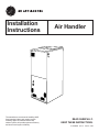
Air Handler
Installation
Instructions
READ CAREFULLY.
KEEP THESE INSTRUCTIONS
.
The manufacture recommends installing AHRI
listed matched indoor and outdoor system.
Installing approved matched indoor and
outdoor system will provide optimum efficiency
and best overall system reliability.


31-5000486 Rev. 2 3
Thank you for purchase this product from GE Appliances, a Haier
company. This installation manual will help you to get the best
performance.
For future reference, record the model and serial number located on
the label on the side of your air conditioner, and the date of purchase.
Staple your proof of purchase to this manual to aid in obtaining
warranty service if needed.
_______________________________________
Model number
_______________________________________
Serial number
_______________________________________
Date of purchase
To register your new air handler, go to
http://www.haierductless.com/product-registration and input the
model/serial number information on this page. To receive a 10-year
compressor and parts warranty, registration is required within 60
days of installation.
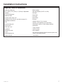
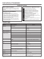
Table of Contents
Record Keeping
SAFETY INFORMATION .........................................................................4
OVERVIEW ...................................................................................6
ACCESSORIES. . . . . . . . . . . . . . . . . . . . . . . . . . . . . . . . . . . . . . . . . . . . . . . . . . . . . . . . . . . . . . . . . . . . . . . . . . . . . . . .6
REQUIRED TOOLS FOR INSTALLATION ...........................................................7
UNIT DIMENSIONS ............................................................................8
MAIN PARTS .................................................................................9
INSTALLATION INSTRUCTIONS ................................................................ 10
CONVENTIONAL LINE SET INSTALLATION ....................................................... 11
REFRIGERANT LINE INSTALLATION .............................................................11
INSTALL CONDENSATE DRAIN .................................................................12
ELECTRICAL REQUIREMENTS .................................................................13
DUCT SYSTEM ...............................................................................13
HEATER KIT .................................................................................14
ELECTRICAL CONNECTIONS ..................................................................14
THERMAL EXPANSION VALVE ................................................................. 15
THERMOSTAT CONNECTION .................................................................. 16
AIR FLOW ADJUSTMENT INSTRUCTIONS FOR CONNECT SERIES ................................... 18
FINAL CHECK ................................................................................19
TROUBLESHOOTING .........................................................................19
LIMITED WARRANTY ......................................................................... 21

4 31-5000486 Rev. 2
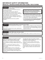
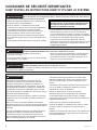
WARNING
For your safety, the information in this manual must be followed to minimize the risk of fire,
electric shock, or personal injury.
• Use this equipment only for its intended purpose as
described in this manual.
• This air handler must be properly installed in
accordance with these instructions before it is used.
• All wiring should be rated for the amperage value listed
on the rating plate. Use only copper wiring.
• All electrical work must be completed by a qualified
electrician and completed in accordance with local and
national building codes.
• Any servicing must be performed by a qualified
individual.
• All air conditioners contain refrigerants, which under
federal law must be removed prior to product disposal.
If you are disposing of an old product with refrigerants,
check with the company handling disposal.
• R-410A systems require that contractors and technicians
use tools, equipment and safety standards approved
for use with this refrigerant. DO NOT use equipment
certified for R22 refrigerant only.
WARNING
RISK OF ELECTRIC SHOCK. Could cause injury or death.
• An adequate ground is essential before connecting the
power supply.
• Disconnect all connected electric power supplies before
installation or service.
• Repair or replace immediately all electrical wiring that
has become frayed or otherwise damaged. Do not use
wiring that shows cracks or abrasion damage along its
length or at either end.
WARNING
This unit is not intended for use by persons (including
children) with reduced physical, sensory or mental
capabilities, or lack of experience and knowledge.
To avoid danger of suffocation, keep the plastic bag or
thin film used as the packaging material away from young
children.
Be sure not to allow foreign materials to enter the
refrigerant piping. Seal the ends of refrigerant piping
before storage.
For installation purposes, be sure to use the parts
supplied by the manufacturer or other prescribed parts.
The use of non-prescribed parts can cause serious
accidents such as the unit falling, water leakage, electric
shock, or fire.
The rated power supply of this product is 208/230
VAC/60hz/1PH. Verify the voltage is within the 187~253
range before turning the equipment on.
Supply power to the air handler should be from a
dedicated circuit that meets branch circuit ampacity
requirements.
Use a special branch circuit breaker and disconnect
switch matched to the power circuit capacity of the air
handler. Install in accordance with national and local
code.
WARNING
RISK OF FIRE. Could cause injury or death.
•
Do not store or use combustible materials, gasoline or other flammable vapors or liquids in the vicinity of this or any
other appliance.
For any service which requires entry into the
refrigerant sealed system, Federal regulations
require that the work is performed by a technician
having a Class II or Universal certification.
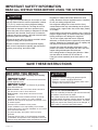
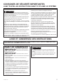
IMPORTANT SAFETY INFORMATION
READ ALL INSTRUCTIONS BEFORE USING THE SYSTEM

31-5000486 Rev. 2 5
SAVE THESE INSTRUCTIONS
FOR MORE HELP, VISIT HAIERAPPLIANCES.COM OR CALL THE CONSUMER HELP LINE AT 877-337-3639.
It is highly recommended that you do not open or close
the stop valves when the outdoor temperature is below
-5°F (-21°C), as this may cause refrigerant leakage.
Do not touch the fins of the coil. Touching the coil fins
could result in damage to the fins or personal injury.
Ensure the power circuit capacity is adequate for all loads
connected to the electrical service panel. Increase the
conductor and panel capacity if the total electrical loads
exceed the power source capacity.
Contact the power utility if the power provided is below
equipment rating plate requirements.
Be sure to install a breaker of the specified capacity.
Refer to local requirements regarding type and kind of
breaker, power wiring, and control cable.
Regulation of cables and breaker differs from each
locality. Be aware of these regulations prior to installtion.
Do not use existing refrigerant lines.
Use refrigerant tubing that is clean and free of any
contamination which may cause damage to the system,
including sulfur, copper oxide, dust, metal chips, powder,
oil, or water.
Avoid coupling lines whenever possible. Use a continuous
length of copper tubing, as oxides formed during improper
brazing techniques can damage the equipment.
Do not use copper pipes that have a collapsed,
deformed, or discolored portion (especially on the interior
surface). Otherwise, the expansion valve or capillary tube
may become blocked with contaminants.
Improper line sizing will degrade performance. Peak
pressure of R410A is much higher than R22. Use ACR
copper tubing with adequate wall thickness.
Use a tubing bender to change piping direction. Make
sure the radius of the bend is no less than 4”.
If the pipe is bent repeatedly at the same place, it will
break.
BEFORE YOU BEGIN
Read these instructions completely and carefully.
• IMPORTANT – Save these instructions
for local inspector’s use.
•
IMPORTANT – Observe all governing
codes and ordinances.
• Note to Installer – Be sure to leave these instructions
with the owner to use for future reference.
• Note to Owner – Keep these instructions for future
reference.
• Skill level – A licensed certified technician (to handle
refrigerant R-410A, recovery, etc.) and a qualified
electrician are required for equipment and service of this
air handler system.
• Use team lift for installation of this product.
• Proper installation is the responsibility of the installer.
• Product failure due to improper installation is not covered
under the limited warranty.
• For personal safety, this system must be properly
grounded.
• Protective devices (fuses or circuit breakers) acceptable
for installation are specified on the nameplate of each unit.
• Piping or wiring within walls must be protected per local code.
CAUTION
• Aluminum electrical wiring may present special
problems - consult a qualified electrician.
• When the unit is in the STOP position, there is still
voltage to the electrical controls.
OUTDOOR REQUIUREMENTS
There is a matching air handler and must be used with
the outdoor units as rated by AHRI.
The outdoor sections are manufactured with an
interchangeable refrigerant metering device for optimum
refrigerant control and system performance. The AHRI
rating may require the metering device be changed, in
some cases, to meet the rated performance.
CAUTION
IMPORTANT SAFETY INFORMATION
READ ALL INSTRUCTIONS BEFORE USING THE SYSTEM

6 31-5000486 Rev. 2
It is the responsibility of the installer to ensure all
installation aspects of this product adhere to national,
state, and local codes.
Every possible system difference or work site abnormality
cannot be addressed in this manual. If questions arise, it
is the obligation of the installer to contact the distributor or
supplier of this product for assistance.
To ensure proper performance, the duct system pressure
drop should never exceed the static pressure capacity of
the blower.
Only use and apply accessory heater components that
are approved in this manual.
All work should be performed by persons trained,
experienced, and licensed in the mechanical and
electrical fields.
The manufacturer will not be responsible for equipment
that is under-performing due to a failure to follow the
instructions in this manual or best industry practices.
The manufacturer has the right to revise this manual
without notice.
1. No person should operate, maintain, or service this
equipment unless suitably trained by an industry
professional.
2. Disconnect unit from the power supply if it not to be used
for an extended period.
3. Be certain that you have selected the proper model for the
operating load. Improper selection may impact operating
performance.
4. Please do not disassemble the unit without proper
training. This equipment has undergone strict inspection
and operational testing at the factory.
5. For technical assistance, please contact GE Appliances
technical support
6. If the product is malfunctioning and/or is inoperable,
please contact GE Appliances technical support. Provide
the following information:
a. Product Nameplate data (model number, cooling / heating
capacity, product serial number, factory date)
b. Nature of Malfunction (specify the circumstances before
and after the error occurred)
7. All illustrations and information in the instruction manual
are for reference only. We retain the right to make
necessary revisions to the product from time to time.
8. GE Appliances assumes no responsibility for personal
injury, property loss or equipment damage caused by
improper installation and commissioning, unecessary
maintenance, or failure to follow relevant federal and state
regulations, industry standards, and the requirements of
this instuction manual.
9. GE Appliances will bear no responsibilities for personal
injury or property damage caused by the following:
a. Improper use of the appliance
b. Altering, maintaining, or operating the product with non-
approved equipment.
c. Altering, maintaining, or operating the product outside of
the guidelines of this manual.
d. Defects caused by corrosive gas.
e. Defects caused by shipping damage.
f. Failure to abide by this instruction manual or government
regulations.
g. Products made by other manufacturers
h. Natural disasters, improper installation environment, or
force majeure.
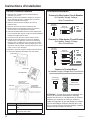
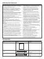
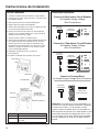
Overview
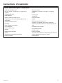
Accessories
Part Looks Like Quantity
Owner’s Manual
Owner’s
Manual
1
Optional Liquid Side Stub Kit
Owner’s
Manual
1
To connect the unit with the liquid pipe
Optional Gas Side Stub Kit
Owner’s
Manual
1
To connect the unit with the gas pipe

31-5000486 Rev. 2 7
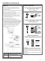
Installation Instructions
Required Tools for Installation
• 18-8 thermostat wire
• 5/8” (16mm), 7/8” (22mm), 1” (25mm) or Adjustable
Wrench
• R-410A Refrigerant*
• Adhesive tape*
• Conduit cable clamp 1/2”*
• Copper line set (for size, see table on page 15)
• #2 phillips screwdriver
• Drill
• R-410A flaring tool
• Hex wrench
• Hole saw 2 1/4”
• Insulation*
• Refrigerant scale
• Level
• Manifold gauge set
• Measuring tape
• Micron gauge
• Mini-split adapter (5/16”F to 1/4”M)
• Nitrogen*
• Pipe cutter
• PVC pipe
• Razor knife
• Reamer
• Saddle clamp (L.S.) w/ screws
• Sealant, non-expanding (for lineset hole)
• Soap/water solution* or gas leakage detector
• Stud finder
• Torque wrench
• Vacuum pump
• Wire strippers
• All usual and customary HVAC hand and power tools,
meters, and testing devices
* consumable

8 31-5000486 Rev. 2
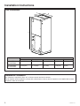
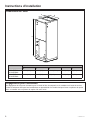
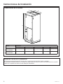
Unit Dimensions
A
H
W
D
B
Installation Instructions
Installation Clearances
24” clearance is required for filter, coil, or blower removal and service access.
The air handler can be installed in a closet with a false bottom to form a return air plenum or be installed with a return
air plenum under the air handler.
Model Dimension
W D H A B
UUY24ZGDAA
UUY36ZGDAA
21-1/4(540) 21-1/4(540) 48-1/4(1224) 11-5/8(295) 20(508)
UUY48ZGDAA
UUY60ZGDAA
24-3/4(630) 21-1/4(540) 57(1448) 11-5/8(295) 20(508)

31-5000486 Rev. 2 9
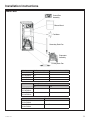
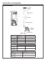
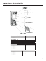
Main Parts
Control Box
Assembly
Blower Wheel
Fan Motor
Secondary Drain Pan
Evaporator
Assembly
Primary Drain Pan
Installation Instructions
Model Filter Size
UUY24ZGDAA
UUY36ZGDAA
20” x 20”
UUY48ZGDAA
UUY60ZGDAA
21” x 20”
Model Motor @ 230V ~, 60Hz
HP FLA
UUY24ZGDAA
UUY36ZGDAA
1/2 2.1
UUY48ZGDAA
UUY60ZGDAA
1 3.2
Model Cooling capacity (ton) Optional electric heater (kW)
UUY24ZGDAA 2.0 8
UUY36ZGDAA 3.0 8
UUY48ZGDAA 4.0 15
UUY60ZGDAA 5.0 15

10 31-5000486 Rev. 2
CAUTION
Prior to installation, turn off all electrical power supplies
intended for use with this equipment.
WARNING
• This air handler is designed for indoor installation
only. Do not install it outdoors.
• When installing the air handler, take consideration to
minimize the length of refrigerant tubing as much as
possible.
• When installing in an area directly over a finished
ceiling (such as an attic), installation of an emergency
drain pan is required directly under the unit. See local
and state code for requirements.
• When installing this unit in an area that may become
wet, elevate the unit with a sturdy,
non-porous material. Install a protective barrier per
code for installations that may be subject to damage,
such as a garage.
• This air handler is designed for a complete supply
and return duct system. DO NOT operate this product
without attaching a completed duct system.
DO NOT install the air handler in a location above or
below the outdoor unit that violates the instructions
provided with the outdoor unit. Service clearance is
to take precedence. Allow a minimum of 24” service
clearance in front of the unit.
• If this air handler is to be installed in an enclosed
space containing fossil fuel burning appliances,
vehicle exhaust emissions, or other potential carbon
monoxide sources, all code requirements for these
conditions must be strictly followed. Carbon monoxide
emissions can be circulated throughout the occupied
space by the air handler’s duct system, causing death
or serious illness.
1. Checking Product Received
After receiving the product, please check for any
damage caused by transportation. Shipping damage
is the responsibility of the carrier. Verify the model
number, specifications, and accessories are correct
prior to installation. The distributor or manufacturer
will not accept claims from dealers for transportation
damage or installation of incorrectly shipped units.
The manufacturer assumes no responsibility for the
installation of incorrectly delivered units.
2. Before Installation
Carefully read all instructions for the installation prior
to installing. Make sure each step or procedure is
understood and any special considerations are taken
into account before starting installation. Assemble all
tools, hardware and supplies needed to complete the
installation. Some items may need to be purchased
separately. Make sure everything needed to install the
product is on hand before starting.
3. Codes and Regulations
This product is designed and manufactured to comply
with national codes. It is installer’s responsibilities
to install the product in accordance with such codes
and/or any prevailing local codes/regulations. The
manufacturer assumes no responsibilities for equipment
installed in violation of any codes or regulations.
4. Replacement Parts
When reporting shortages or damages, or ordering
repair parts, give the complete product model and serial
numbers as stamped on the nameplate. Replacement
parts are available through your contractor or local
distributor.
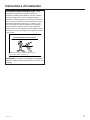
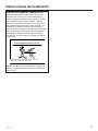
Installation Instructions
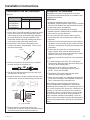
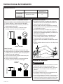
Typical installation configurations as shown
Upflow Horizontal Left

31-5000486 Rev. 2 11
Conventional Line Set Installation
Pipe Size
Model External Diameter (inch)
Gas pipe Liquid Pipe
UUY24ZGDAA
UUY36ZGDAA
UUY48ZGDAA
UUY60ZGDAA
3/4 3/8
Proper flaring is essential to achieve an airtight seal.
1. Ensure there is enough insulation to protect the entire
line set from end to end. Use multiple light passes
when cutting tubing to the desired length, tightening
the cutting wheel only until light resistance is felt.
Ream both outside and inside, holding tube down to
keep reaming chips from falling into the tube.
2. Use the flare nuts from the accessories pouch,
located in the indoor unit packaging. Fit the nut on
the tubing to be flared.
Flare nut
Copper pipe
3. Remove the seal over the exposed end, and place
the tube into the R-410A flaring tool.
4. Run the tube against the flaring tool pipe stop, and
clamp the form on the tube.
5. Rotate the handle of the die clockwise until the clutch
releases, then remove the flared tubing from the form.
Flare form
Pipe
A
A = ~1/16” (1.6mm)
6. Examine the flare to make sure there are no
imperfections on the lip of the flare, and that the back
of the flare exactly fits the seat of the flare nut.
Installation Instructions
Refrigerant Line Installation
Refrigerant lines must be connected by a licensed,
EPA certified refrigerant technician in accordance with
established procedures.
IMPORTANT:
• Connecting refrigerant lines must be clean,
dehydrated, refrigerant-grade copper lines. Air handler
coils should be installed only with specified line sizes
for approved system combinations.
• Use care with the refrigerant lines during the
installation process. Sharp bends or possible kinking
in the lines will cause a restriction.
• Do not remove the caps from the lines or system
connection points unit connections are ready to be
completed.
1. Route the suction and liquid lines from the fittings on
the indoor coil to the fittings on the outdoor unit. Run
the lines in a direct path, avoiding unnecessary turns
and bends.
2. Ensure that the suction line is insulated over the
entire exposed length and that both suction and
liquid lines are not in direct contact with floors, walls,
ductwork, floor joists, or other piping.
3. Connect the suction and liquid line to the evaporator
coil.
4. To avoid damage; remove the TXV sensing bulb
while brazing. Relocate rubber grommets away from
the heat to avoid melting them.
5. Braze with an alloy of silver or cooper and
phosphorus with a melting point above 1,100°F.
NOTE: Do not use soft solder.
6. Reinstall the TXV sensing bulb and the rubber
grommets after brazing is finished.
7. Make sure the outdoor air conditioning unit has been
put in place according to the Installation Instructions
and is connected to the refrigerant lines.
While brazing, purge the system with Nitrogen to
prevent contamination. Manufacturer recommends
reattaching and insulating the TXV sensing bulb at a 10
or 2 o’clock position on the suction line, outside the coil
housing, no more than one foot from the connection.
Evacuate the system to 500 microns to ensure proper
air and moisture removal (Note: Deep evacuation or
triple evacuation method recommended). Open the
suction service valve slowly and allow the refrigerant to
bleed into the system before opening the liquid service
valve.

12 31-5000486 Rev. 2
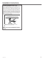
Installation Instructions
Install Condensate Drain (cont.)
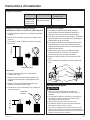
1. Pour several quarts of water into the drain pan,
enough to fill drain trap and line.
2. Check to make sure the drain pan is draining
completely, no leaks are found in drain line fittings,
and water is draining from the end o the primary
drain pan.
3. Correct any leaks found.
Insulate pipe as needed
Vent must extend a minimum of 2”
above the drain pan
Drain Pan
Pitch horizontal
drain lines
downward 1” per 10'
2” Min.
3/4” MPT Connector
2” Min.
Drain Line and Vent Tee
Vent
“T”
Drain Line
Clean Out
Press in
(DO NOT GLUE)
Reducing Tee with
1” Slip Hex Plug
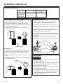
Install Condensate Drain
The air handler is provided with 3/4” NPT condensate
drain connections.
A field fabricated secondary drain pan with a drain
pipe to the outside of the building is required in all
installations over a finished living space or in any area
that may be damaged by overflow from the main drain
pa. In some localities, local codes require secondary
drain pan for any horizontal installations. The secondary
drain pan must have a larger footprint than the air
handler.
1. Remove the appropriate panel knockouts for drains.
See “Drain Pan Connections” section. You may need
to remove the indoor coil assembly from the cabinet.
2. Determine the drain connection to be used and
note differences between the primary (green) and
secondary (red) openings. Drain plugs are provided
for all openings; remove and discard the appropriate
plugs with 1/2” drive ratchet and verify that remaining
plugs are tight (2.5 ft-lbs). Attach drain line to pan
with 3/4” make pipe thread PVC fittings. Hand tight is
adequate—do not over tighten and do not reduce the
line size.
3. Secondary drain connections should be connected
to a separate drainage system. Run this drain to
a place in compliance with local installation codes
where is will be secondary drain indicates a plugged
primary drain.
4. Install a 2” trap in the primary drain line as close to
the unit as practical. Make sure the top of the trap
is below the connection to the drain pan to allow
complete drainage of the pan.
NOTE: Horizonal runs must also have an anti-siphon
air vent (standpipe) installed ahead of the horizontal
run. An extremely long horizontal run may require an
oversized drain line to eliminate air trapping.
NOTE: Do not operate air handler without a drain trap.
The condensate drain is on the negative pressure
side of the blower; therefore being pulled through the
condensate line will prevent positive drainage without a
proper trap.
5. Route the drain line to the outside or to an
appropriate drain. Drain lines must be installed so
they do not block serviceaccess to the front of the air
handler. A 24” clearance is required for filter, coil, or
blower removal and service access.
NOTE: Check local codes before connecting the drain
line to an existing drainage system.
6. Insulate the drain lines where sweating could cause
water damage.
Upon completeion of installation, it is the responsibility
of the installer to ensure the drain pan(s) is capturing
all condensate, and all condensate is draining properly
and not getting into the duct/system.

31-5000486 Rev. 2 13
Installation Instructions
Electrical Requirements
Model Power Supply Recommended breaker
size (A)
UUY24ZGDAA
UUY36ZGDAA
UUY48ZGDAA
UUY60ZGDAA
208/230V-1Ph-60Hz 15
Control wiring” to “Electric wiring
Using 18 Gauge Solid Core Copper Wire
1. Cut back the insulation 1” from the end of the wire.
2. Remove the screw from the terminal block, and wrap
the wire around the screw.
3. Return the screw and wire to the terminal block and
tighten securely.
Jacket / Insulation
1” (25mm)
Stranded Wire
1. Cut back the insulation 3/8” from the end of the wire.
2. Make sure the round or forked terminal connector is
rated for the amperage of the unit being installed.
3. Use a crimping tool only to fasten the connector to the
wire.
4. Return the screw and connector to the terminal block
and tighten securely.
Solderless
Terminal
3/8” (10mm)
Wiring Connections
1. High and low voltage wires should be led through
different rubber rings of the electric box cover.
2. To avoid communication errors, maintain as much
separation as possible between the power and control
wiring.
3. High and low voltage wires should be secured
separately. Secure the former ones with large clamps
and the latter ones with small clamps.
4. Use screws to tighten high and low voltage wiring on
the terminal board. Improper connection may create a
fire hazard.
5. Ground the units by connecting the ground wire.
6. All wiring must comply with local and national code.
Screw with
Special Fastener
Round
Terminal
Wire
Terminal
Board
Duct System
CAUTION
1. Ensure that the power supply is disconnected prior to
installing the heater kit.
2. A means of strain relief and conductor protection must
be provided at the supply wire entrance into cabinet.
3. Only use copper conductors.
4. Installation must follow The National Electrical Code
and other applicable codes.
5. If this appliance is installed in an enclosed area, such
as a garage or utility room with any carbon monoxide
producing appliance, ensure that area is properly
ventilated to the outside.

14 31-5000486 Rev. 2
Installation Instructions
Heater Kit
1. Refer to the table for the appropriate heater kit.
2. Check for any physical damage; do not install a
damaged heater kit.
3. Remove the upper access panel from the air handler.
4. Remove cover plate from air handler.
5. Slide the heater kit into the slot and secure element
plate with previously removed screws.
6. Insert power leads into the circuit breaker lugs or
stripped red and black wires (for heater kit without
circuit breaker) and tighten.
7. Connect ground wire to ground lug.
8. Knock off appropriate area of the plastic circuit
breaker cover on the access panel of the air handler.
Knock off the holes according to the actual installation
number and positions of circuit breakers. If circuit
breaker is not installed, do not knock off the holes,
otherwise there maybe has electric shock occur.
9. Replace access panel and check operation.
10. Finalize power and control wiring.
Cover Plate
Heater Kit
Circuit Breaker
Bolt
Fig 2.9
Kit # Description
UAZEH08A 8kW Heater with 45A breaker
UAZEH15A 15kW Heater with 30A and 60A
breakers
Electrical Connections
ATTENTION: If it is new air handler and it is the first
time install heat, make sure the L1/L2 wire to heater
breaker, then wire the ground wire. Use proper wire
size as specified in this manual for 8K and 15 K heater
assemblies.
If there is no heat kit to install, please make sure wire to
terminal block.
Connect to 8kw heater Circuit Breaker
Air Handler Supply Voltage
Wire Connections
Field Supply
Ground Wires
208/230 Volt
Field Supply Wires
Connect to 15kw heater Circuit Breaker
Air Handler Supply Voltage
Wire Connections
Field Supply
Ground Wires
208/230 Volt
Field Supply Wires
Connect to Terminal Block
Air Handler Supply Voltage Wire Connections
208/230 Volt
Field Supply Wires
Field Supply
Ground Wires
L1
L2

31-5000486 Rev. 2 15
Installation Instructions
Thermal Expansion Valve (TXV)
Factory Installed Expansion Valves: Sensing bulbs are
factory installed and clamped to the suction line. For
optimum performance, reattach and insulate the bulb
at a 10 or 2 o’clock position outside of the cabinet to
the main suction line no more than one foot from the
suction line connection. If necessary, the bulb can be
installed on a vertical suction line. In this instance, the
bulb must be placed before any trap, with the bulb’s
capillary tube facing upward.
Thermal Expansion Valve (Letter A)
NOTE: Some models are equipped with thermo expansion
valve and do not require any orifice change.
NOTE: The coil comes pre-charged with refrigerant
R410A. The coil must be evacuated if the TXV valve is
changed.

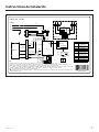
16 31-5000486 Rev. 2
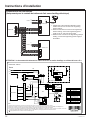
Thermostat Connections
(Only for air handler without electric heater)
ATTENTION: Thermostat must energize reversing valve in heat mode using the “B” terminal.
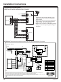
Installation Instructions
Indoor Unit
Outdoor Unit
Power
Power
Thermostat
Y
B
W1
R
C
G
Y
B
W1
R
C
G
Y
B
W1
R
C
G
L2
L1
XT1
XT2
L2
L1
G
L2
L1
G
L2
L1
XT1
XT2
X1
X1
8kw Heat Kit
See Note
G
CB1CB1
AP1
Power
G
L1
L2
Fan motor
X1
1
XT3
DC_MOTOR1
TC
RD
BK
BU
YE
WH
1
X1
2 3 4 5 6
G
M
XT1-1
XT1-2
8KW HEAT KIT
G
CB1 CB1
L1
L2
G
YEGN
W1
W2
BK
RD
AP2
G
CN1
COM2
W7 W8
W9
W10
W11
W12
Thermostat
Heat
W13
X1 X2
X10
X4
X3
X9 X13X7
Y
B
W1
R
C
G
Y
XT2
C
Y
G G
Y
C
B B B
W1 W1 W1
R R R
C
①
W5
W6
W3
W4
N 2
1
XT1
1
Code Name
CB1 Circuit breaker
TC Transformer
XT1~XT3 Wiring board
Y
B
4-way valve control
signal, energized under
the heating mode
W1 Heater control signal
R 24V AC power supply
C 24V common
G Indoor unit fan signal
Indoor Unit - 2/3 ton
Note:
1. Please refer to the Instruction Manual to check
whether the unit can connect to the engineerig
electric heating.
2. When the unit doesn't connect to the engineering
electric heating, connect the engineering power
supply to the L1 and L2 of wiring board.
3. When the unit connects to the engineering electyric
heating, connect the engineering power supply to
the breaker.
Note:
1. Please refer to the instruction manual to check whether the unit can connect to the engineering electric heating.
2. When the unit doesn’t connect to the engineering electric heating, connect the engineering power supply to the W5(BK) and W6(WH) of X1.
3. When the unit connects to the engineering electric heating, connect the engineering power supply to the breaker.
4. The primary input voltage of transformer is defaulted at 230V(BK). When switching the power supply of the complete unit to 208V, connect the
primary input voltage of transformer to 208V(BU), which can be realized by exchanging the black wire and the blue wire.
5. 1 Only applicable for the unit whose motor is with earthing wire.

31-5000486 Rev. 2 17
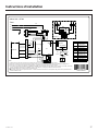
Installation Instructions
AP1
Power
Indoor Unit - 4/5 ton
L1
L2
1
XT3
TC
RD
BK
BU
YE
WH
1
X1
2 3 4 5 6
G
W1
W2
G
CN1
W7 W8
W9
W10
W11
Thermostat
W13
X1 X2
X10
X4
X3
X9 X13 X7
Y
B
W1
R
C
G
Y
XT2
C
Y
G G
Y
C
B B B
W1 W1 W1
R R R
C
W5
W6
W3
W4
N 2
1
XT1
1
W14
X1
G
CB1 CB2
CB2
CB1
L1
L2
G
15KW Heat kit
Heat
Code Name
CB1
Circuit breaker only for
10KW heat kit
CB2
Circuit breaker only for
5KW heat kit
TC Transformer
XT1~XT3 Wiring board
Y
B
4-way valve control
signal, energized under
the heating mode
W1 Heater control signal
R 24V AC power supply
C 24V common
G Indoor unit fan signal
G
Fan
motor
M
XT1-1
XT1-2
YEGN
BK
RD
AP2
COM2
W12
①
DC_MOTOR1
4
4
Note:
1. Please refer to the instruction manual to check whether the unit can connect to the engineering electric heating.
2. When the unit doesn’t connect to the engineering electric heating, connect the engineering power supply to the W5(BK) and W6(WH) of X1.
3. When the unit connects to the engineering electric heating, connect the engineering power supply to the breaker.
4. The primary input voltage of transformer is defaulted at 230V(BK). When switching the power supply of the complete unit to 208V, connect the
primary input voltage of transformer to 208V(BU), which can be realized by exchanging the black wire and the blue wire.
5. 1 Only applicable for the unit whose motor is with earthing wire.
6. As for wiring, please refer to the parameters before “ /” of MCA and MOP of heat kit on the nameplate for CB1; please refer to parameters after “ /”
of MCA and MOP for CB2.

18 31-5000486 Rev. 2
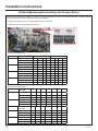
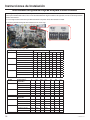
Installation Instructions
Airflow Adjustments Instructions for Connect Series
Default airflow setting of air handler is in speed 1. It can be adjusted by using the control board dip switch to different speed
according to Water static(Pa). Operation Instruction is below:
1. Dip switch settings must be completed before power on the unit.
2. Airflow dip switch is indicated by the red circle.
Model Level Heat (SA2) Cool (SA1)
UUY24ZGDAA Speed 1-CFM (L) Default ON OFF ON OFF ON OFF ON OFF
Speed 2-CFM (M) ON OFF OFF ON ON OFF OFF ON
Speed 3-CFM (H) ON OFF OFF OFF ON OFF OFF OFF
UUY36GDAA Speed 1-CFM (L) Default ON ON OFF ON ON ON OFF ON
Speed 2-CFM (M) ON ON OFF OFF ON ON OFF OFF
Speed 3-CFM (H) ON OFF ON ON ON OFF ON ON
UUY48ZGDAA Speed 1-CFM (L) Default OFF ON OFF OFF OFF ON OFF OFF
Speed 2-CFM (M) OFF OFF ON ON OFF OFF ON ON
Speed 3-CFM (H) OFF OFF ON OFF OFF OFF ON OFF
UUY60GDAA Speed 1-CFM (L) Default OFF ON ON ON OFF ON ON ON
Speed 2-CFM (M) OFF ON ON OFF OFF ON ON OFF
Speed 3-CFM (H) OFF ON OFF ON OFF ON OFF ON
DIP Switch Configuration
Model Static Pressure -
Inches W.C.
0 0.1 0.15 0.2 0.3 0.4 0.5
UUY24ZGDAA Speed 1-CFM (L) 1050 940 910 850 720 - -
Speed 2-CFM (M) 1200 1070 1010 950 820 630 -
Speed 3-CFM (H) 1280 1180 1130 1080 970 790 660
UUY36ZGDAA Speed 1-CFM (L) 1230 1100 1000 950 900 - -
Speed 2-CFM (M) 1315 1230 1190 1145 1050 900 -
Speed 3-CFM (H) 1430 1325 1275 1225 1120 1050 900
Model Static Pressure -
Inches W.C.
0 0.1 0.2 0.3 0.4 0.5 0.6
UUY48ZGDAA Speed 1-CFM (L) 1650 1550 1470 1320 1210 - -
Speed 2-CFM (M) 1830 1730 1580 1500 1400 1280 -
Speed 3-CFM (H) 2000 1915 1810 1700 1590 1480 1350
UUY60ZGDAA Speed 1-CFM (L) 1850 1750 1600 1540 1440 - -
Speed 2-CFM (M) 2020 1930 1830 1730 1630 1530 -
Speed 3-CFM (H) 2100 2050 1950 1840 1750 1640 1580
Blower Performance Data

31-5000486 Rev. 2 19
Installation Instructions
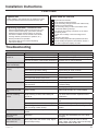
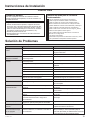
Troubleshooting
Problem Possible Causes Solution
The unit cannot be
turned on.
The unit is not connected to the power supply Connect to power supply
Low voltage Check if circuit voltage is within rated scope.
The fuse is broken or the breaker shorted out Replace fuse or connect breaker
The unit operates but
stops immediately.
Air inlet/outlet of indoor unit is blocked. Remove obstacles.
Abnormal cooling or
heating.
Air inlet/outlet of indoor unit is blocked. Remove obstacles.
Inaccurate temperature setting. Adjust setting at wired controller.
Doors or windows are opened. Close the door or windows.
Direct sunshine. Draw curtain or louver.
Too much heat source in the room. Reduce heat source.
Filter screen is blocked by dirt. Clean the filter.
Unit doesn’t run. When unit is started immediately after it is
just turned off.
Overload protection switch makes it run after
3 minutes delay.
When power is turned on. Standby operating for about 1 minute.
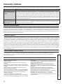
Mist comes from the
unit.
Under cooling. Indoor high humidity air is cooled rapidly.
The unit is making
noises
Slight cracking sound is heard when just
turned on.
It is noise when electronic expansion valve
initialization.
There is consecutive sound when cooling. That’s sound for gas refrigerant flowing in the
unit.
There is sound when unit starts or stops. That’s sound for gas refrigerant stops flowing.
There is slight and consecutive sound when
unit is running or after running.
That’s sound for operation of drainage
system.
The unit blows out dust. When unit runs after no operation for a long
period.
Dust in indoor unit is blew out.
The unit smells
abnormal
Operating. The room odor absorbed by the unit is blew
out again.
Indoor unit still runs
after switch off.
After every indoor unit receive “stop” signal,
fan will keep running.
Indoor fan can be set as “ON” or “AUTO”
mode. Under “ON” mode, indoor fan will keep
running after switch off the unit.
Final Check
System Test
Please explain to the customer how to operate the system
by using the Owner’s Manual found with the indoor unit.
Check Items for Test Run
No gas leak from linesets?
Are the linesets insulated properly?
Are the connecting wirings of indoor and outdoor firmly
inserted to the terminal block?
Is the connecting wiring of indoor and outdoor fixed?
Is condensate draining correctly?
Is the ground wire securely connected? Is the indoor
unit securely fixed?
Is power source voltage correct according to local
code?
Is there any odd noise?
Does the cooling temperature drop between 20-30°F?
Does the heating temperature raise between 30-40°F?
Is the room temperature display accurate?
Explaining Operation To the End User
• Using the User Manual, explain to the user how to use
the air conditioner/heat pump, (the remote controller,
adding/removing the air filters, placing or removing
the remote controller from the remote control holder,
cleaning methods, precautions for operation, etc.)
• Review precautions for operation.
• Recommend that the user read the Operating
Instructions carefully.

20 31-5000486 Rev. 2
Notes
La page est en cours de chargement...
La page est en cours de chargement...
La page est en cours de chargement...
La page est en cours de chargement...
La page est en cours de chargement...
La page est en cours de chargement...
La page est en cours de chargement...
La page est en cours de chargement...
La page est en cours de chargement...
La page est en cours de chargement...
La page est en cours de chargement...
La page est en cours de chargement...
La page est en cours de chargement...
La page est en cours de chargement...
La page est en cours de chargement...
La page est en cours de chargement...
La page est en cours de chargement...
La page est en cours de chargement...
La page est en cours de chargement...
La page est en cours de chargement...
La page est en cours de chargement...
La page est en cours de chargement...
La page est en cours de chargement...
La page est en cours de chargement...
La page est en cours de chargement...
La page est en cours de chargement...
La page est en cours de chargement...
La page est en cours de chargement...
La page est en cours de chargement...
La page est en cours de chargement...
La page est en cours de chargement...
La page est en cours de chargement...
La page est en cours de chargement...
La page est en cours de chargement...
La page est en cours de chargement...
La page est en cours de chargement...
La page est en cours de chargement...
La page est en cours de chargement...
La page est en cours de chargement...
La page est en cours de chargement...
La page est en cours de chargement...
La page est en cours de chargement...
La page est en cours de chargement...
La page est en cours de chargement...
-
 1
1
-
 2
2
-
 3
3
-
 4
4
-
 5
5
-
 6
6
-
 7
7
-
 8
8
-
 9
9
-
 10
10
-
 11
11
-
 12
12
-
 13
13
-
 14
14
-
 15
15
-
 16
16
-
 17
17
-
 18
18
-
 19
19
-
 20
20
-
 21
21
-
 22
22
-
 23
23
-
 24
24
-
 25
25
-
 26
26
-
 27
27
-
 28
28
-
 29
29
-
 30
30
-
 31
31
-
 32
32
-
 33
33
-
 34
34
-
 35
35
-
 36
36
-
 37
37
-
 38
38
-
 39
39
-
 40
40
-
 41
41
-
 42
42
-
 43
43
-
 44
44
-
 45
45
-
 46
46
-
 47
47
-
 48
48
-
 49
49
-
 50
50
-
 51
51
-
 52
52
-
 53
53
-
 54
54
-
 55
55
-
 56
56
-
 57
57
-
 58
58
-
 59
59
-
 60
60
-
 61
61
-
 62
62
-
 63
63
-
 64
64


GE AUH2436ZGDA Guide d'installation
- Catégorie
- Climatiseurs split-system
- Taper
- Guide d'installation
dans d''autres langues
- English: GE AUH2436ZGDA Installation guide
- español: GE AUH2436ZGDA Guía de instalación
Documents connexes
Autres documents
-
Maytag C7B(A,H)M0 Guide d'installation
-
-
Medallion C6BH-X Guide d'installation
-
Haier AP48DS1ERA Operation Manual And Installation Manual
-
Maytag B5VM-IQ Guide d'installation
-
ClimateMaster Dedicated Outside Air Systems Le manuel du propriétaire
-
Samsung AM036TNZDCH/AA Guide d'installation
-
Unbranded R6GD 3 - 5 Ton, 3 Phase Guide d'installation
-
Dometic Aircommand Heron 2.2 Guide d'installation
-
Trane Horizon OANE360A Installation, Operation and Maintenance Manual