Metrologic IS421X ScanGlove Mode d'emploi
- Catégorie
- Lecteurs de codes à barres
- Taper
- Mode d'emploi
Ce manuel convient également à

METROLOGIC INSTRUMENTS, INC.
IS421X ScanGlove
®
Laser Bar Code Scanner
Installation and User’s Guide
MLPN 2187
Printed in USA
October 1998

ii
Locations:
USA Corporate Headquarters Europe
Metrologic Instruments, Inc. Metrologic Instruments GmbH
90 Coles Road Dornierstrasse 2
Blackwood, NJ 08012 82178 Puchheim b.
Customer Service: 1-800-ID-METRO Munich, Germany
Tel: 609-228-8100 Tel: 49-89-89018-0
Fax: 609-228-6673 Fax: 49-89-89019-200
www.metrologic.com
ASIA
South America Metrologic Asia (PTE) Ltd.
Metrologic Instruments 31, Kaki Bukit Road 3
Rua Flórida, 1.821-5°Andar-Brooklin #05-08 Techlink
CEP 04571-090, São Paulo-SP, Brasil Singapore 417818
Outside Brazil: Tel: 65-842-7155
Tel: 55-11-5505-6568 Fax: 65-842-7166
Fax: 55-11-5505-1681 [email protected]
In Brazil:
Tel: 55-11-5505-2396
Fax: 55-11-5507-2301
Copyright
© 1998 by Metrologic Instruments, Inc. All rights reserved. No part of this work may
®
be reproduced, transmitted, or stored in any form or by any means without prior written
consent, except by reviewer, who may quote brief passages in a review, or provided for
in the Copyright Act of 1976.
Products and brand names mentioned in this document are trademarks of their
respective companies.

iii
Table of Contents
Introduction ................................................... 1
Unpacking List ................................................. 1
Theory of Operation ............................................. 2
Connecting the IS4210 or IS4213 ScanGlove to a Decoder/Controller ..... 3
Parts of the ScanGlove Scanner ................................... 4
Audible Indications ............................................. 5
Visual Indications ............................................ 6-9
Labels ....................................................... 10
IR Sensor Activation ........................................... 11
Scan Field ................................................... 11
Depth of Field and Symbol Specification ........................... 12
Maintenance .................................................. 13
Appendix A
Specifications ......................................... 14
Appendix B
IS4210 and IS4213 Pin Assignments .................... 15, 16
IS4215 Pin Assignments ............................. 17, 18
Appendix C
Warranty and Disclaimer ............................. 19, 20
Appendix D
Notices ........................................... 21, 22
Appendix E
Patents ............................................... 23
Index .................................................... 24, 25

1
Introduction
The ScanGlove™ non-decode scanners interface directly into decode equipped
"keyboard wedges," controllers, or decode, they are designed distinctly to
accommodate many types of applications.
When using the ScanGlove™ with a decoder, scanner operation is dependent
upon your decoder. Since there are many decoders available, refer to the
decoder’s documentation concerning scanner requirements and operation.
Unpacking List
With the purchase of a ScanGlove scanner, the following will be in the
shipping carton:
! Installation and User’s Guide
! ScanGlove Laser Bar Code Scanner
! Glove
To order additional items, contact your dealer, distributor or call Metrologic’s
Customer Service Department.

2
Theory of Operation
When connected to a decoder/controller and to the signals as defined in the pin
assignment sections, the IS4210 and IS4213 scanners will operate as follows.
The scanning process initiates by an infrared (IR) device located behind the
window. The IR sensor is active as long as the power is applied to the unit.
When the IR sensor detects an object, the green LED will flash. When the
laser decodes a bar code, the scanner transmits the data to the host system and
then " beeps" to show the decoding is complete. The IR sensing range can be
programmed for two ranges.
Short Range Activation - The IR signal initiates the scan process if it senses
an object anywhere from the face of the window out to approximately 4" to 7".
Long Range Activation - The IR signal initiates the scan process if it senses
an object anywhere from the face of the window out to approximately 9" to
13".
If the object is removed from the field during the scanning process, the laser
turns off and the scanner reenters "standby" mode.
However, if the object stays in the field, the laser remains on for up to 2.5
seconds trying to detect another bar code. If the scanner does not detect a bar
code, the scanner reenters "standby" mode. To reactivate the scanning
sequence, remove the object and present another.
If the same symbol stays in the field after a successful scan, the laser stays on
for approximately 4 seconds and then turns off. This prevents uninten-tional
reads of the same bar code. To read the same symbol more than once, remove
the object from the scan field for approximately 1 second and then present the
symbol again.

3
Connecting the IS4210 or IS4213 ScanGlove to a
Decoder/Controller
Important Note: To maintain compliance with applicable standards, all
circuits connected to the scanner must meet the requirements for SELV (Safety
Extra Low Voltage) according to EN 60950.
Since each host system is unique, configure the decoder/controller to match
your host system requirements. Refer to the Installation and User’s Guide for
further information.
Since there are many different types of decoders, refer to your decoder’s
documentation to connect the decoder to your host system.
1. Make sure the host system is off and the ON/OFF toggle switch on the
controller is in the OFF (O) position.
2. Connect the 9-pin squeeze end of the scanner adaptor cable to the
decoder/ controller. Then, attach the 15-pin connector of the host’s
communication cable to the decoder/controller. Connect the other end
of the cable to the host device.
3. If the decoder/controller receives power from an external power supply,
check the AC input requirements of the transformer/power supply to
make sure the voltage matches an available AC outlet. Connect the
power supply to the decoder/controller. (The socket-outlet can be
installed near the equipment so it will be easily accessible.)
4. Supply power to the scanner and decoder/controller by plugging the
power supply into the AC outlet. Position the decoder ON/OFF switch
to the ON (1) position and then power up the host system.
Note: When the ScanGlove first receives power, it will immediately go
through a self diagnostic routine, then the red and green LED will
flash and the unit will beep once.
When positioning the ScanGlove, make sure to align the output
window flush with the knuckles of your hand. Also, avoid
obstructing the output window. Rings and fingers may prevent the
scanner from reading a bar code.

4
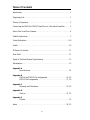
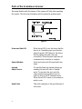
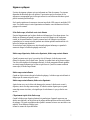
Figure 1
Parts of the ScanGlove Scanner
Becoming familiar with the features of the scanner will help when operating
the scanner. The following illustration and list explain the pertinent parts.
Green and Red LED When the red LED is on, this shows that the
laser is on. Depending upon your decoder,
when the green LED flashes on, this shows
that the scanner has read a bar code
successfully. When the green light turns off,
communication to the host is complete.
Output Window Sends and receives the IR signal and Laser
beam.
Infrared If a specified time has elapsed without any
Object Sensor scanning, the unit will enter a “standby”
mode. To reactivate the unit, point the
output window downwards or wave an
object in front of the IR (infrared) sensor.
When the red LED comes on, the scanner is
ready to scan.
Head Cable This cable terminates to the specifications of
each order.

5
Audible Indicators
Audible indicators show the status of the scanner. These indicators are
dependent upon the decoder being used. The function of these indications may
not work as described below if the decoder pinouts and software controls do
not match the pin out signals as defined in the pin assignment section of this
manual.
To change the volume (four settings are available) or turn the beeper off, refer
to the Programming Guide section: Beeper Tones.
One Beep When the scanner first receives power, the red LED will
blink, followed by the green LED, and then the scanner will
"beep." After the scanner performs this start-up sequence, the
scanner is ready to scan.
When the scanner successfully reads a bar code, the green
light will flash and "beep" once. If the scanner does not
"beep" or the green LED does not flash then the bar code
read is not successful.
Razzberry If, upon power up, the scanner emits a razzberry tone,
Tone then the scanner has failed diagnostics.
Note: The scanner can be programmed to emit a razzberry
tone when the timeout occurs during communica-
tion between the host and scanner. Refer to the Pro-
gramming Guide section: Audible Indicators for
Communication Timeouts.

6
Visual Indicators
There are visual indicators to show the status of the scanner. These indicators
are dependent upon the decoder being used. The function of these indicators
may not work as described below if the decoder pinouts and software controls
do not match the pin out signals as defined in the pin assignment section of this
manual.
There are a red LED and a green LED at the top of the scanner. When the
scanner is on, the flashing or steady activity of the LEDs indicates the status of
the scan and scanner.
No Red or Green Illumination of the LEDs will not occur if the scanner
has remained dormant for a specified time and the
scanner is not receiving power from the host. To
reactivate the unit, direct the output window up then
down toward the object.
Red Flash; When the scanner first receives power, the red LED
Green Flash; will flash, followed by the green LED, and then "beep"
Steady Red once. After the scanner performs this startup sequence,
the red LED will remain on for a specified time show-
ing that the scanner is ready to scan. If an object is not
presented to the scanner, the red light will turn off.
Steady Red When the laser is on, the red LED will be on. This
occurs when an object is in the scan field. If the scanner
cannot detect a bar code within approximately 2.5
seconds, the red LED will shut off indicating that the
laser is no longer on.
Steady Red; When the scanner successfully reads a the scanner does
Green Flash not bar code, the green LED will flash and "beep"
once. If "beep" or the green LED does not flash then
the bar code read is not successful.
Repetitive When the red LED flashes several times while it rests
Red Flashes upon a stationary surface, then an object is within the
scan field and is activating the IR sensor. To eliminate
this disturbance, direct the scan window toward a diff-
erent location.

7
Signaux optiques
Il existe des signaux optiques qui vous informent sur l'état du scanner. Ces signaux
dépendent du décodeur que vous utilisez. Il peut arriver que les fonctions de ces
signaux ne correspondent pas à celles qui suivent si vous utilisez un décodeur qui n'a
pas été construit par Metrologic.
Sur la partie supérieure du scanner se trouvent une diode LED rouge et une diode LED
verte. Les diodes rouge et verte clignotantes ou allumées vous informent sur l'état de
palpage et de scanner.
Ni la diode rouge, ni la diode verte n'est allumée
Il arrive fréquemment que les deux diodes ne s'allument pas. Pour deux raisons. Les
diodes ne s'allument pas quand le scanner ne reçoit de l'énergie ni de l'ordinateur
central, ni du transformateur. Quand le scanner reçoit de l'énergie et ne s'allume
cependant pas, le scanner est resté pendant une certaine période sansêtre utilisé et le
laser et le moteur sont désactivés.
Pour réactiver l'unité, déplacer un objet devantle palpeur infrarouge ou prendre le
scanner et diriger la fenêtre de palpage vers le bas.
Diode rouge clignotante; diode verte clignotante; diode rouge restant allumée
Quand le scanner reçoit pour la première fois de l'énergie, la diode rouge se met
d'abord à clignoter, puis la diode verte. Ensuite, le scanner émet un bip sonore unique.
Une fois cette séquence de démarrage effectuée, la diode rougereste allumée pendant
un certain temps indiquant que le laser est prêt à servir. Quand le scanner nedétecte
aucun objet, la diode rouge s'éteint.
Diode rouge restant allumée
Quand un objet se trouve devant la fenêtre de palpage, la diode rouge reste allumée et
indique que le scanner est prêt à servir.
Diode rouge restant allumée; diode verte clignotante
Après lecture avec succès d'un code barres par le scanner, la diode verte se met à
clignoter, suivie d'un bip sonore unique. Si la diode vertene clignote pas ou quand
aucun bip sonore n'est émis, cela signifie que le code barres n'a pas pu être lu avec
succès.
Clignotement répété de la diode rouge
Quand la diode rouge clignote plusieurs fois pendant que l'appareil repose sur une
surface non déplacée, un objet activant le palpeur infrarouge setrouve devant la fenêtre
de palpage. Ceci peut se produire même quand le scanner se trouve sur une table ou un
reposoir. Pour éliminer ce défaut, posi-
tionner le scanner de façon différente.

8
Optische Anzeigen
Es sind optische Anzeigen vorhanden, die Ihnen Aufschluß über den Scannerstatus
geben. Diese Anzeigen sind abhängig von dem von Ihnen verwendeten Dekodierer. Es
kann sein, daß die Funktionen dieser Anzeigen nicht den nachfolgend angegebenen
entsprechen, falls Sie einen Dekodierer verwenden, der nicht von Metrologic hergestellt
wurde.
Auf der Oberseite des Scanners befinden sich zwei Leuchtdiodenanzeigen: eine rote
und eine grüne. Die blinkenden bzw. feststehenden Leuchtdiodenanzeigen geben
Aufschluß über den Abtast- und Scannerstatus.
Weder rote noch grüne Leuchtanzeige
Es kommt häufig vor, daß die beiden Leuchtdiodenanzeigen nicht aufleuchten. Dafür
gibt es zwei mögliche Gründe. Die Anzeigen leuchtennicht, wenn der Scanner weder
vom Hostrechner noch vom Transformator Energie erhält. Erhält der Scanner Energie,
und die Anzeigen leuchten dennoch nicht auf, so ist der Scanner für einen bestimmten
Zeitraum untätig geblieben, und Laser und Motor sind abgeschaltet. Zur Reaktivierung
der Einheit sollten Sie ein Objekt vor dem Infrarot-Sensorhin- und herbewegen oder
den Scanner aufnehmen und das Abtastfenster nach unten richten.
Rote Blinkanzeige; Grüne Blinkanzeige; feststehende rote Leuchtanzeige
Wenn dem Scanner erstmalig Energie zugeführt wird, blinkt zunächst die rote
Leuchtdiodenanzeige auf, gefolgt von der grünen Leuchtdiodenanzeige,
und anschließend sendet der Scanner ein einmaliges Piep-Signal aus. Nach Ausführung
dieser Startsequenz leuchtet die rote Leuchtdiodenanzeige für einen bestimmten
Zeitraum auf und zeigt an, daß der Scanner zur Durchführung des Scannens bereit ist.
Wird dem Scanner kein Objekt präsentiert, so erlischt die rote Leuchtanzeige.
Feststehende rote Leuchtanzeige
Befindet sich ein Objekt vor dem Ausgabefenster, so leuchtet die rote Leuchtdiode
weiterhin auf und zeigt an, daß der Scanner zur Durchführung des
Abtastvorgangs bereit ist.
Feststehende rote Leuchtanzeige; grüne Blinkanzeige
Nach erfolgreichem Lesen eines Barcodes durch den Scanner blinkt die grüne
Leuchtdiodenanzeige auf, gefolgt von einem einmaligen Piep-Signal. Falls die grüne
Leuchtdiodenanzeige nicht aufblinkt oder der Scanner kein Piep-Signal aussendet,
bedeutet dies, daß der Barcode nicht erfolgreichgelesen werden konnte.
Wiederholte rote Blinkanzeigen
Blinkt die rote Leuchtdiodenanzeige mehrmals auf, während das Gerät auf einer
nichtbewegten Fläche liegt, so befindet sich ein Objekt innerhalb des Abtastfeldes, das
den Infrarot-Sensor aktiviert. Dies kann selbst dann vorkommen, wenn der Scanner auf
dem Ladentisch oder dem Ablagegestell liegt. Um diese Störung zu beseitigen sollten
Sie den Scanner anders positionieren.

9
Segnali ottici
Sono previsti dei segnali ottici che Vi informano sullo stato dello scanner. Questi
segnali dipendono dal decodificatore da Voi utilizzato. Se utilizzate un decodifi-catore
che non è stato fabbricato dalla Metrologic è possibile che le funzioni di questi segnali
non corrispondano a quelle qui di seguito indicate.
Sulla parte superiore dello scanner si trovano due diodi luminosi: uno rosso e uno verde.
I diodi luminosi, che possono o essere accesi in continuazione o lampeggiare, Vi
informano sullo stato della scansione e dell’apparecchio.
Né il diodo luminoso rosso né quello verde sono accesi
Succede spesso che i due diodi luminosi non siano accesi. Vi sono due cause possibili.
Se lo scanner non viene alimentato né dal calcolatore host né dal trasformatore, i diodi
luminosi non sono accesi. Se invece lo scanner viene alimentato e ciònonostante i diodi
luminosi non sono accesi, lo scanner è rimasto disattivato per un determinato periodo e
laser e motore sono spenti. Per riattivare l’unità dovreste muovere un oggetto davanti al
sensore a infrarossi oppure prendere lo scanner e rivolgere il finestrino di scansione
verso il basso.
Il diodo luminoso rosso lampeggia; il diodo luminoso verde lampeggia; il diodo l-
uminoso verde è acceso
Quando lo scanner viene alimentato per la prima volta, lampeggia dapprima il diodo
luminoso rosso e quindi quello verde. Poi lo scanner emette un unico segnale beep.
Dopo l’esecuzione di questa sequenza di avvio, il diodo luminoso rosso si accende per
un determinato periodo ed indica che il laser è pronto per effettuare una scansione. Se
allo scanner non viene presentato nessun oggetto, il diodo luminoso rosso si spegne.
Il diodo luminoso rosso è acceso
Se un oggetto si trova davanti al finestrino di uscita, il diodo luminoso continua ad
essere acceso indicando così che lo scanner è pronto per effettuare una scansione.
Il diodo luminoso rosso è acceso; il diodo luminoso verde lampeggia
Dopo la lettura riuscita di un codice a barre da parte dello scanner il diodo luminoso
verde lampeggia e quindi viene emesso un unico segnale beep. Se il diodo luminoso
verde non lampeggia oppure lo scanner non emette un segnale beep, ciò significa che la
lettura del codice a barre non è riuscita.
Il diodo luminoso rosso lampeggia ripetutamente
Se il diodo luminoso rosso lampeggia ripetutamente mentre l’apparecchio si trova su
una superficie immobile, vi è un oggetto all’interno della zona di scansione che attiva il
sensore a infrarossi. Ciò può essere addirittura il caso quando lo scanner si trova sul
banco oppure nel suo supporto. Per eliminare questa anomalia basta cambiare la
posizione dello scanner.

10
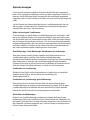
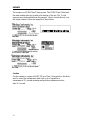
Labels
The scanner is a CDRH Class II laser system. The CDRH Class II label and
the serial number label are located at the bottom of the unit. The “Avoid
exposure laser light emitted from this aperture” label is located directly over
the output window. Below are examples of these labels:
Caution
For the scanner to comply with IEC 825 as a Class 1 laser product, the device
used to control the scanner must limit each cycle of operation to
a maximum of 3.5 seconds scanning and provide a minimum reaction
time of 1 second.

11
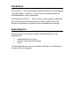
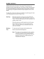
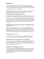
Figure 2
Figure 3
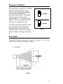
IR Sensor Activation
The scanning process initiates by an infrared
(IR) sensor located behind the output
window. In short range mode the signal it
projects extends approximately 4" - 7"
beyond the output window. In long range
mode the signal it projects extends
approximately 9" - 13" beyond the output
window. The IR sensor remains active as
long as power is applied to the unit.
The mode wanted can be manually enabled
by repositioning the Short Range/Long
Range switch that is on the side of the
ScanGlove (refer to Figure 2). Short range
activation is down; long range activation is
up.
Scan Field
The depth of field for the scanner is 38.1 mm to 139.7 mm (1.5" to 5.5") from
the face of the output window (Refer to Figure 3).

12
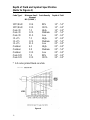
Figure 4
Depth of Field and Symbol Specification
(Refer to Figure 4)
Code Type* Minimum Small Code Density Depth of Field
Element
Mil. (1/1000")
UPC/EAN 10.4 80% 1.5" - 5.5"
UPC/EAN 13.0 100% 1.5" - 6.0"
Code 39 7.5 High 1.5" - 4.0"
Code 39 12.0 Medium 2.5" - 5.5"
Code 39 21.0 Low 3.0" - 6.5"
I 2 of 5 7.5 High 1.5" - 4.0"
I 2 of 5 12.0 Medium 3.0" - 5.5"
I 2 of 5 21.0 Low 2.5" - 6.0"
Codabar 6.5 High 2.5" - 4.0"
Codabar 9.8 Medium 2.0" - 5.0"
Codabar 13.0 Low 2.0" - 6.0"
Code 128 7.0 80% 2.0" - 4.0"
Code 128 13.0 100% 3.0" - 6.0"
* All codes printed black on white.

13
Maintenance
Smudges and dirt can interfere with the proper scanning of a bar code.
Therefore, the output window will need occasional cleaning.
1. Spray glass cleaner onto lint free, non-abrasive cleaning cloth.
2. Gently wipe the output window.

14
Appendix A
Specifications
Application: Hand mounted laser bar code scanner
Light Source: VLD 675 ± 5 nm
Max. Laser Power: 1.0 mW
CDRH: Designed to meet Class II laser product
UL/CSA: Designed to meet UL 1950; CSA, C22.2 No.
950
EMI: Designed to meet FCC Class A
IEC: Class I
Mechanical
Dimensions: 71mm L x 51mm W x 27mm H (2.8" x 2.0"x 1")
Weight: 180g (6.35 oz.)
Electrical
Power (Watts): .75
Input Voltage, DC: 5V
Operating Current (Amps): 135 - 145 mA
Standby Current (Amps): 18 mA
Operational
Depth of Field, UPC 100%: 38.1 mm to 139.7 mm (1.5" to 5.5")
Scan Speed: 70 scan lines per second
Scan Pattern: Single scan line
Maintenance: Clean output window periodically
Print Contrast: 35% minimum reflectance difference
Roll, Pitch, Yaw: 42E, 68E, 52E
Environmental
Storage Temperature: -40EC to 60EC (-40EF to 140EF)
Operating Temperature: 0EC to 35EC (32EF to 95EF)
Humidity: 5% to 95% relative humidity, non-condensing
Light Levels: Up to 3200 foot candles; works in direct
sunlight
Ventilation: None required
Shock: Drop of 1.5 meters (5')
ESD: 15 kV IEC 801-2 Level 4
Contaminants: Sealed to resist airborne particulate
contaminants
Specifications subject to change without notice.

15
Appendix B
IS4210 and IS4213 Pin Assignments
The IS4210 and IS4213 scanners both terminate with a 9-pin female squeeze
connector. The pin numbers impress on the connector.
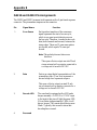
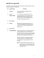
Pin Signal Name Function
1 Scan Sense Each positive transition of the scan sense
signal represents the start of a scan cycle,
which is one pass in each direction across
the bar code. Therefore, it sends the bar code
data (both forwards and reverse) between the
rising edges. There are 35 scan sense pulses
per second, which equals 70 scans per
second.
Note: The polarity does not show scan
direction.
This open collector output can sink 25 mA
via an external pull up resistor connected to
a voltage not to exceed +20 VDC.
2 Data Data is an output digital representation of the
scanned bar code. A low level represents a
bar and a high level represents a space.
This open collector output can sink 25 mA
via an external pull up resistor connected to a
voltage not to exceed +20 VDC.
3 Decode LED The scan head is equipped with a LED and a
beeper assembly. A +5VDC to 12 VDC input
to the head at this pin will light the green LED.
If it oscillates at approximately 2 KHz, it will
drive a beeper. The current should be no more
30mA. Typically, this is used to show that
decoding has occurred.
4 Reserved

16
5 Proximity Detect The proximity detect is a grounding switch that
is active while an object is in the specified
detection field. The controlling computer should
provide a +5 VDC pull up. Ground the +5 VDC
pull up when the proximity detect activates.
This shows that an object has moved within
scanning range. We recommend that this signal
debounce for approximately 30 milliseconds.
Note: We did not make the design of this scan
head to have the continual enabling of
the laser as if the scanner is in a perm-
anent mounting fixture.
6 Laser/ A +5 VDC input to the head. Its use is to start
Motor Control the flipper motor and signal processor, and
enable the visible laser diode (VLD). This can
be a TTL level signal and require less than 1
milliampere of current.
7 Ground A power ground that can handle a 500-
milliampere load.
8 SHIELD Cable shield to chassis ground (no load).
9 +5 VDC Supply Primary laser diode/motor power input. +5
VDC should be present at this pin and can
supply up to 125 mA when enabled by the
signal at pin 6.

17
IS4215 Pin Assignments
The IS4215 scanner terminates with a 25-pin male D-type connector. The pin
numbers impress on the connector:
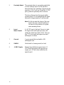
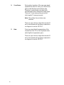
Pin Signal Name Function
7 Ground A power ground that can handle a 500-
milliampere load.
13 Laser/ A +5 VDC input to the head. Its use is to
Motor Control start the flipper motor and signal processor,
and enable the visible laser diode (VLD).
This can be a TTL level signal and require
less than 1 milliampere of current.
18 No Connect
19 Power Primary laser diode/motor power input. +5
VDC should be present at this pin and it can
supply up to 125 mA when enabled by the
signal at pin 6.
20 No Connect
23 Proximity Detect The proximity detect is a grounding switch that
is active while an object is in the specified
detection field. The controlling computer should
provide a +5 VDC pull up. Ground the +5 VDC
pull up when the proximity detect activates.
This shows that an object has moved within
scanning range. We recommend that this
signal debounce for approximately 30 milli-
seconds.
Note: We did not make the design of this scan
head to have the continual enabling of the
laser as if the scanner is in a perm-anent
mounting fixture.
La page est en cours de chargement...
La page est en cours de chargement...
La page est en cours de chargement...
La page est en cours de chargement...
La page est en cours de chargement...
La page est en cours de chargement...
La page est en cours de chargement...
La page est en cours de chargement...
-
 1
1
-
 2
2
-
 3
3
-
 4
4
-
 5
5
-
 6
6
-
 7
7
-
 8
8
-
 9
9
-
 10
10
-
 11
11
-
 12
12
-
 13
13
-
 14
14
-
 15
15
-
 16
16
-
 17
17
-
 18
18
-
 19
19
-
 20
20
-
 21
21
-
 22
22
-
 23
23
-
 24
24
-
 25
25
-
 26
26
-
 27
27
-
 28
28


Metrologic IS421X ScanGlove Mode d'emploi
- Catégorie
- Lecteurs de codes à barres
- Taper
- Mode d'emploi
- Ce manuel convient également à
