Metrologic MS7100 Manuel utilisateur
- Catégorie
- Lecteurs de codes à barres
- Taper
- Manuel utilisateur

METROLOGIC INSTRUMENTS, INC.
MS7100 Series Fixed Projection
Laser Scanner
Installation and User’s Guide
MLPN 2408
Printed in USA
October 1998

ii
Locations:
USA Corporate Headquarters Europe
Metrologic Instruments, Inc. Metrologic Instruments GmbH
90 Coles Road Dornierstrasse 2
Blackwood, NJ 08012 82178 Puchheim b.
Customer Service: 1-800-ID-METRO Munich, Germany
Tel: 609-228-8100 Tel: 49-89-89018-0
Fax: 609-228-6673 Fax: 49-89-89019-200
www.metrologic.com
ASIA
South America Metrologic Asia (PTE) Ltd.
Metrologic Instruments 31, Khaki Bukit Road 3
Rua Flórida, 1.821-5°Andar-Brooklin #05-08 Techlink
CEP 04571-090, São Paulo-SP, Brasil Singapore 417818
Outside Brazil: Tel: 65-842-7155
Tel: 55-11-5505-6568 Fax: 65-842-7166
Fax: 55-11-5505-1681 [email protected]
In Brazil:
Tel: 55-11-5505-2396
Fax: 55-11-5507-2301
Copyright
© 1998 by Metrologic Instruments, Inc. All rights reserved. No part of this work may
®
be reproduced, transmitted, or stored in any form or by any means without prior written
consent, except by reviewer, who may quote brief passages in a review, or provided for
in the Copyright Act of 1976.
Products and brand names mentioned in this document are trademarks of their
respective companies.

iii
Table of Contents
Introduction ................................................... 1
Scanner and Accessories ......................................... 2
Quick Start .................................................... 3
Operational Test ............................................... 4
Scanner Installation: Powered by External Power Supply ............... 5
Scanner Installation: Powered by the Host Device ..................... 6
Scanner Installation: to the PC for the Scanner with built-in
PC Keyboard Wedge Interface .................................... 7
Scanner Parts .................................................. 8
Audible Indicators ............................................. 9
Failure Modes ......................................... 10
Visual Indicators .............................................. 11
Labels ....................................................... 12
Depth of Field Specifications .................................... 13
Optimal Depth of Field .................................. 13
Close Depth of Field .................................... 13
Normal Depth of Field .................................. 14
Far Depth of Field ...................................... 14
Minimum Bar Code Element From Scanner Face .................... 15
Optimal Depth of Field .................................. 15
Close Depth of Field .................................... 16
Normal Depth of Field .................................. 17
Far Depth of Field ...................................... 18
Maintenance .................................................. 19
Troubleshooting Guide ...................................... 20-25
Application and Protocols ....................................... 26

iv
Appendix A
Design Specifications 27, 28
Appendix B
Default Settings 29-32
Appendix C
Pin Assignments 33-35
Appendix D
Warranty and Disclaimer 36, 37
Appendix E
Notices 38, 39
Index 40, 41

1
Introduction
Orbit™ is an aggressive, omnidirectional laser bar code scanner. Light-weight
and rugged, Orbit is small in size, but BIG in performance. Designed for
applications where counter space is limited, Orbit is the ideal presentation
scanner for retail, convenience, liquor and specialty stores. In addition, Orbit’s
unique, contoured shape allows it to be picked-up and used as a hand-held
scanner when scanning large or bulky items.
Engineered with a large, easy-to-find optimal scan area, Orbit increases the
first pass read rate for maximum productivity. The scanning head can be tilted
vertically a full 30 for added flexibility when scanning various sized objects.
o
These features increase the scanning throughput without increasing the
scanner size.
SCANNER INTERFACE
7100-41 RS-232/Light Pen ready (KBW)
7100-47 Keyboard Wedge ready (KBW)
7100-67 RS-232 ready (OCIA)
7100-9 OCIA ready (OCIA)
7100-11 IBM 46XX/RS-232 ready (IBM)
Orbit offers a great deal of features to the consumer:
‚ Fully automatic scanning operation
‚ PowerLink compatible
‚ Easy programming
‚ 7 beeper tones
‚ Programmable depth of field
‚ Data editing

2
Scanner and Accessories
The following is a list of the parts included in the MS7100 kit.
! MS7100 Hand-Held Laser Scanner - Refer to page 26 for available
communication protocols
! Power Transformer AC in 120V, 220V- 240V Continental
European or 220V- 240V UK. DC in regulates 5.2V@650mA
(MLPN45593/45591/45592)
! MLPN 2408 User’s and Installation Guide
Access MetroSelect Programming Guide MLPN 2407 on the web
http://www.metrologic.com
RS-232, Light Pen, some OCIA and some 46xx scanners:
! PowerLink cable with built in power jack:
Standard - MLPN 54xxx* - 2.1m (7') straight cord, short strain relief
or
Optional - MLPN 53xxx* - 2.7m (9') coiled cord, long strain relief
*xxx specifies connection to the host
Keyboard Wedge Scanners:
! Keyboard Wedge PowerLink Cable with a 5-pin
DIN female connector on one end and a 6-pin
mini DIN male on the other (MLPN 19763)
! Adapter Cable with a 5-pin DIN male
connector on one end and a 6-pin mini DIN
female connector on the other (MLPN
19716)
Other items may be ordered for the specific protocol being used. To order additional
items, contact the dealer, distributor or call Metrologic’s Customer Service Depart-ment
at 1-800-ID-METRO or 1-800-436-3876.

3
Quick Start
1.) Plug in the scanner. When the MS7100 is ready to scan,
the red LED will turn on, then the green LED will flash
and the scanner will beep once. (the green LED will
remain on for the duration of the beep).
2.) The scanner is shipped from the factory programmed with
default settings. To configure the MS7100 scanner to meet
the host system’s specific needs, refer to the MetroSelect
Programming Guide (MLPN 2407) for instructions on
how to enter the program mode and to select the appro-
priate bar codes.

4
Operational Test
Metrologic recommends using the external power supply provided with the
scanner when operating the MS7100. When using power supplied by the host,
the host system should supply a minimum of 250 mA of current @ 5VDC.
Keyboard Wedge Scanners:
1. Connect the 10-pin modular plug of the PowerLink cable into the scanner
jack. Connect the other end of the PowerLink Y-type cable
to the PC. Connect the 5-pin female DIN side of the Y-type cable
into the keyboard connector on the PC and connect the 6-pin male
mini-DIN side into the PC.
2. Check the AC input requirements of the power supply to make sure the
voltage matches the AC outlet. Connect AC power to the transformer.
3. Listen for a single beep that indicates the scanner is ready for use.
(steady red LED and the green LED will flash once)
RS-232, Light Pen, OCIA and 46xx scanners:
1. Connect the 10-pin modular plug of the PowerLink cable into the scanner
jack. Connect the other end of the PowerLink cable (the 9-pin D-type
connector) to the PC.
2. Check the AC input requirements of the power supply to make sure the
voltage matches the AC outlet. Connect AC power to the transformer.
3. Listen for a single beep that indicates the scanner is ready for use.
(steady red LED and the green LED will flash once)

5
Scanner Installation: Powered by External Power Supply
To maintain compliance with applicable standards, all circuits connected to the
scanner must meet the requirements for SELV (Safety Extra Low Voltage)
according to EN 60950.
1. Turn off the host system.
2. Make the necessary PowerLink cable connections to the scanner and
the host.
3. Connect the external transformer into the power jack on the Power Link
cable.
4. Check the AC input requirements of the power supply to make sure the
voltage matches the AC outlet. (the socket-outlet shall be installed near
the equipment and shall be easily accessible.) Connect AC power to the
transformer.
5. Turn on the host system.
NOTE:
a. When the scanner first receives power, the red LED will turn
on. Then the scanner will beep once and the green LED will
flash simultaneously.
b. Plugging the scanner into the serial port of the PC does not
guarantee that scanned information will appear at the PC. A
software driver and correct configuration setting are also
required for proper communication to occur.

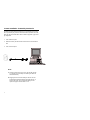
6
Scanner Installation: Powered by Host Device
The MS7100 scanner interfaces terminate to a 10-pin modular jack. Connect
the 10-pin modular plug of the PowerLink cable into the jack then connect the
other end of the PowerLink cable to the host. Refer to Appendix C page 33 for
pin assignments.
1. Turn off the host system.
2. Make the necessary PowerLink cable connections to the scanner and the
host.
3. Turn on the host system.
NOTE:
a. When the scanner first receives power, the red LED will turn
on. Then the scanner will beep once and the green LED will
flash simultaneously.
b. Plugging the scanner into the serial port of the PC does not
guarantee that scanned information will appear at the PC. A
software driver and correct configuration setting are also
required for proper communication to occur.

7
Scanner Installation to the PC for the Scanner with Built-in
PC Keyboard Wedge Interface
To maintain compliance with applicable standards, all circuits connected to the
scanner must meet the requirements for SELV (Safety Extra Low Voltage)
according to EN 60950.
1. The MS7100 Keyboard Wedge scanner interface terminates to a 10-pin
modular jack. Connect the 10-pin modular plug of the PowerLink cable
into the jack. The Power Link cable is terminated with a 5-pin DIN
female connector on one end, and a 6-pin mini DIN male on the other.
Metrologic will supply an adapter cable with a 5-pin DIN male
connector on one end and a 6-pin mini DIN female connector on the
other. According to the termination required, connect the appropriate
end of the adapter cable to the PowerLink cable, leaving the neces-sary
termination exposed for connecting to the keyboard and the keyboard
port on the PC. Refer to Appendix C page 35 for pin assignments.
2. If the PC is on, exit the application and turn the PC off.
3. Disconnect the keyboard from the PC.
4. Connect the scanner as described in step 1. Connect the external
transformer into the power jack on the Power Link cable. Refer to
Manufacturer’s Recommendation below. Connect AC power to the
transformer.
5. Power up the PC.
Manufacturer’s Recommendation:
Metrologic recommends the use of an external power supply with
MS7100-47 Keyboard Wedge applications. Powering the MS7100-47
directly from the com-puter keyboard connector could interfere with
the operation of the scanner or the computer. Not all computers supply
the same current through the keyboard port, this explains why a scanner
would work on one computer and not another.

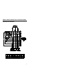
8
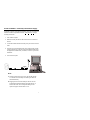
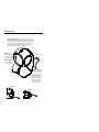
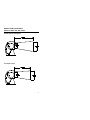
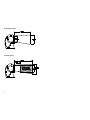
Green and Red LEDs: When the red LED is on, this
indicates that the laser is on. When the green LED flashes on,
the scanner has read a bar code successfully. When the green
light turns off, communication to the host is complete. The
LEDs are also used as diagnostic indicators and mode
indicators. Refer to pages 9-11 for details.
ú
Orbit Face: þ
Tilts 30 vertically
o
for variable position-
ing of the scan pattern.
Output Window: º
Laser light emits
from this aperture.
ü
Cable Connection:
The MS7100 scanner
has a 10-pin modular
jack. The PowerLink
cable will connect its
10-pin modular plug
into the jack. Refer to
pages 5-7 for specific
protocol PowerLink
cable connections.
Side View
Top View
Scanner Parts

9
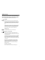
Audible Indicators
When the MS7100 scanner is in operation, it provides audible feedback.
These sounds indicate the status of the scanner. Eight settings are available for
the tone of the beep (normal, 6 alternate tones and no tone). To change the
tone, refer to the MetroSelect Programming Guide MLPN 2407.
One Beep
*
When the scanner first receives power, the red LED will turn
on, then the green LED will flash and the scanner will beep once.
(The green LED will remain on for the duration of the beep.) The
scanner performs this startup sequence, the scanner is ready to
scan.
When the scanner successfully reads a bar code, the green LED
will flash and the scanner beeps once (if programmed to do so).
If the scanner does not beep once and the green light does not
flash, then the bar code has not been successfully read.
Razzberry Tone
This is a failure indicator. Refer to failure modes page 10.
Three Beeps - during operation
***
During operation of the scanner, the green LED will flash
while the scanner simultaneously beeps three times (while going
into programming mode).
The green LED will continue to flash until the unit exits program
mode. Upon exiting program mode, the scanner will beep three
times and the green LED will stop flashing. When configured, 3
beeps can also indicate a communications timeout during normal
scanning mode.
When using one-code-programming, the scanner will beep
three times (the current selected tone), followed by a short
pause then by a high tone and a low tone. This tells the user
that the single configuration bar code has successfully con-
figured the scanner.
Three Beeps - on power up
This is a failure indicator. Refer to failure modes page 10.

10
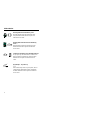
Failure Modes
Flashing Red and One Razzberry Tone
This indicates the scanner has experienced a laser
subsystem failure. Return the unit for repair at an
authorized service center.
Flashing Red and Green and Two Razzberry
Tones
This indicates the scanner has experienced a motor
failure. Return the unit for repair at an authorized
service center.
Continuous Razzberry Tone with both LEDs off
If, upon power up, the scanner emits a continuous razz-
berry tone, then the scanner has an electronic failure.
Return the unit for repair at an authorized service
center.
Three Beeps - on power up
***
If the scanner beeps 3 times on power up then, the non-
volatile memory that holds the scanner configuration
has failed. Return the unit for repair at an authorized
service center.

11
Visual Indicators
There are a red LED and a green LED on the head of the Orbit MS7100.
When the scanner is on, the flashing or stationary activity of the LEDs
indicates the status of the current scan and the scanner.
No Red or Green LED
The LEDs will not be illuminated if the scanner is not receiving
power from the host or transformer.
Steady Red
When the laser is active, the red LED is illuminated. The red
LED will remain illuminated until the laser is deactivated.
During the power save mode, the laser will turn on and turn off.
During this period, the red LED remains illuminated.
Steady Red and Single Green Flash
When the scanner successfully reads a bar code, the green LED will
flash and the scanner will beep once. If the green LED does not flash
or the scanner does not beep once, then the bar code has not been
successfully read.
Steady Red and Steady Green
After a successful scan, the scanner transmits the data to the host
device. Some communication modes require that the host inform the
scanner when data is ready to be received. If the host is not ready to
accept the information, the scanner’s green LED will remain on until
the data can be transmitted.
Steady Red and Flashing Green
This indicates the scanner is in program mode. A razzberry tone
indicates that an invalid bar code has been scanned in this mode.
Steady Green, Red off
This indicates the scanner may be waiting for communication from
the host.

12
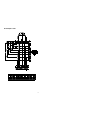
Labels
Each scanner has labels on the bottom of the unit. One label contains
information such as the model number, date of manufacture, serial number and
notes that the device is a Class IIa laser product. The other label states the
device is an LASERKLASSE 1 product. The following are examples of these
labels:

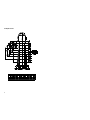
13
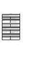
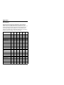
Depth of Field Specifications
(based on 100% UPC bar codes)
Optimal Depth of Field (default)
Close Depth of Field

14
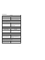
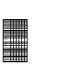
Normal Depth of Field
Far Depth of Field

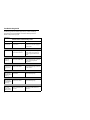
15
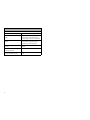
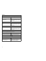
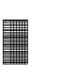
Depth of Field by Minimum Bar Code Element Width
Optimal Depth of Field (default)

16
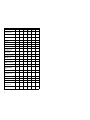
Close Depth of Field
La page est en cours de chargement...
La page est en cours de chargement...
La page est en cours de chargement...
La page est en cours de chargement...
La page est en cours de chargement...
La page est en cours de chargement...
La page est en cours de chargement...
La page est en cours de chargement...
La page est en cours de chargement...
La page est en cours de chargement...
La page est en cours de chargement...
La page est en cours de chargement...
La page est en cours de chargement...
La page est en cours de chargement...
La page est en cours de chargement...
La page est en cours de chargement...
La page est en cours de chargement...
La page est en cours de chargement...
La page est en cours de chargement...
La page est en cours de chargement...
La page est en cours de chargement...
La page est en cours de chargement...
La page est en cours de chargement...
La page est en cours de chargement...
La page est en cours de chargement...
-
 1
1
-
 2
2
-
 3
3
-
 4
4
-
 5
5
-
 6
6
-
 7
7
-
 8
8
-
 9
9
-
 10
10
-
 11
11
-
 12
12
-
 13
13
-
 14
14
-
 15
15
-
 16
16
-
 17
17
-
 18
18
-
 19
19
-
 20
20
-
 21
21
-
 22
22
-
 23
23
-
 24
24
-
 25
25
-
 26
26
-
 27
27
-
 28
28
-
 29
29
-
 30
30
-
 31
31
-
 32
32
-
 33
33
-
 34
34
-
 35
35
-
 36
36
-
 37
37
-
 38
38
-
 39
39
-
 40
40
-
 41
41
-
 42
42
-
 43
43
-
 44
44
-
 45
45


Metrologic MS7100 Manuel utilisateur
- Catégorie
- Lecteurs de codes à barres
- Taper
- Manuel utilisateur
dans d''autres langues
- italiano: Metrologic MS7100 Manuale utente
- English: Metrologic MS7100 User manual
Documents connexes
-
Metrologic MLPN 2168 Manuel utilisateur
-
-
-
-
-
-
-
Metrologic TECH 7 MS770 Installation and User Manual
-
Autres documents
-
DeLOCK 62593 Fiche technique
-
Kensington 62024 Manuel utilisateur
-
Metrologic Instruments MLPN 2159 Manuel utilisateur
-
-
Posiflex TS-2200 Manuel utilisateur
-
MSI 1P14330D22 1P 14 Stylus Pen Mode d'emploi
-
Datalogic Laptop DLL2020-WO Manuel utilisateur
-
NCR All in One Printer 7882 Manuel utilisateur
-
 Boundless VGB10 Manuel utilisateur
-
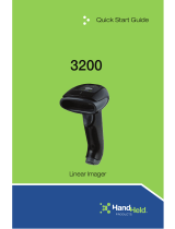 Hand Held Products 3200 Guide de démarrage rapide

