Foundry Networks FES Guide d'installation
- Catégorie
- Commutateurs réseau
- Taper
- Guide d'installation

Foundry FastIron Stackable
Hardware Installation Guide
FastIron Edge Switch
FastIron Edge Switch X-Series
FastIron Workgroup Switch X-Series
4980 Great America Parkway
Santa Clara, CA 95054
Tel 408.207.1700
www.foundrynet.com
June 2006
™

Copyright © 2006 Foundry Networks, Inc. All rights reserved.
No part of this work may be reproduced in any form or by any means – graphic, electronic or mechanical, including
photocopying, recording, taping or storage in an information retrieval system – without prior written permission of the
copyright owner.
The trademarks, logos and service marks ("Marks") displayed herein are the property of Foundry or other third parties.
You are not permitted to use these Marks without the prior written consent of Foundry or such appropriate third party.
Foundry Networks, BigIron, FastIron, IronView, JetCore, NetIron, ServerIron, TurboIron, IronWare, EdgeIron, IronPoint,
the Iron family of marks and the Foundry Logo are trademarks or registered trademarks of Foundry Networks, Inc. in
the United States and other countries.
F-Secure is a trademark of F-Secure Corporation. All other trademarks mentioned in this document are the property of
their respective owners.

June 2006 © Foundry Networks, Inc. iii
Contents
C
HAPTER
1
A
BOUT
T
HIS
G
UIDE
..................................................................................... 1-1
INTRODUCTION ...........................................................................................................................................1-1
W
HAT’S INCLUDED IN THIS EDITION? ...........................................................................................................1-2
A
UDIENCE ..................................................................................................................................................1-3
N
OMENCLATURE .........................................................................................................................................1-3
R
ELATED PUBLICATIONS .............................................................................................................................1-3
H
OW TO GET HELP .....................................................................................................................................1-4
W
EB ACCESS .......................................................................................................................................1-4
E
MAIL ACCESS .....................................................................................................................................1-4
T
ELEPHONE ACCESS ............................................................................................................................1-4
W
ARRANTY COVERAGE ...............................................................................................................................1-4
C
HAPTER
2
P
RODUCT
O
VERVIEW
.................................................................................. 2-1
PRODUCT OVERVIEW ..................................................................................................................................2-1
S
UPPORTED CONFIGURATIONS .............................................................................................................2-2
S
OFTWARE FEATURES ................................................................................................................................2-3
POE A
PPLICATIONS ....................................................................................................................................2-3
W
IRELESS APPLICATIONS ............................................................................................................................2-3
H
ARDWARE FEATURES ...............................................................................................................................2-4
FES2402, FES4802, FES9604 ..........................................................................................................2-4
FES12GCF .........................................................................................................................................2-5
FES2402-POE
AND FES4802-POE ...................................................................................................2-5
FESX424, FESX624,
AND FWSX424 ................................................................................................2-6
FESX424HF .......................................................................................................................................2-6
FESX424-POE ...................................................................................................................................2-7
FESX448, FESX648,
AND FWSX448 .................................................................................................2-7
C
ONTROL FEATURES ............................................................................................................................2-8
F
IBER OPTIC MODULES ......................................................................................................................2-15

Foundry Hardware Installation Guide for the FES, FESX, and FWSX
iv © Foundry Networks, Inc. June 2006
POWER SUPPLIES ..............................................................................................................................2-17
C
OOLING SYSTEM AND FANS ..............................................................................................................2-20
C
HAPTER
3
I
NSTALLING
A
F
AST
I
RON
S
TACKABLE
S
WITCH
............................................. 3-1
UNPACKING A SYSTEM ................................................................................................................................3-1
P
ACKAGE CONTENTS ...........................................................................................................................3-2
G
ENERAL REQUIREMENTS ....................................................................................................................3-2
S
UMMARY OF INSTALLATION TASKS .............................................................................................................3-3
I
NSTALLATION PRECAUTIONS .......................................................................................................................3-4
G
ENERAL PRECAUTIONS .......................................................................................................................3-4
L
IFTING PRECAUTIONS .........................................................................................................................3-4
P
OWER PRECAUTIONS .........................................................................................................................3-4
P
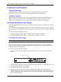
REPARING THE INSTALLATION SITE ............................................................................................................3-6
C
ABLING INFRASTRUCTURE ..................................................................................................................3-6
I
NSTALLATION LOCATION ......................................................................................................................3-6
I
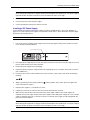
NSTALLING A REDUNDANT POWER SUPPLY .................................................................................................3-6
I
NSTALLING AN AC POWER SUPPLY ......................................................................................................3-6
I
NSTALLING A DC POWER SUPPLY ........................................................................................................3-7
I
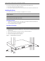
NSTALLING THE DEVICE ..............................................................................................................................3-8
D
ESKTOP INSTALLATION .......................................................................................................................3-8
R
ACK MOUNT INSTALLATION .................................................................................................................3-8
W
ALL MOUNT INSTALLATION .................................................................................................................3-9
P
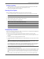
OWERING ON THE SYSTEM .......................................................................................................................3-9
V
ERIFYING PROPER OPERATION .................................................................................................................3-9
O
BSERVING THE POWER STATUS LEDS ..............................................................................................3-10
A
TTACHING A PC OR TERMINAL ................................................................................................................3-10
C
HAPTER
4
C
ONNECTING
N
ETWORK
D
EVICES
AND
C
HECKING
C
ONNECTIVITY
........................................................................... 4-1
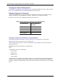
ASSIGNING PERMANENT PASSWORDS .........................................................................................................4-1
R
ECOVERING FROM A LOST PASSWORD ................................................................................................4-2
C
ONFIGURING IP ADDRESSES .....................................................................................................................4-3
D
EVICES RUNNING LAYER 3 SOFTWARE ...............................................................................................4-3
D
EVICES RUNNING LAYER 2 SOFTWARE ...............................................................................................4-4
C
ONNECTING NETWORK DEVICES ...............................................................................................................4-5
C
ONNECTORS ......................................................................................................................................4-5
C
ABLE SPECIFICATIONS ........................................................................................................................4-5
C
ONNECTING TO ETHERNET OR FAST ETHERNET HUBS .........................................................................4-5
C
ONNECTING TO WORKSTATIONS, SERVERS, OR ROUTERS ...................................................................4-6
C
ONNECTING A NETWORK DEVICE TO A FIBER PORT .............................................................................4-6
T
ESTING CONNECTIVITY ..............................................................................................................................4-7
P
INGING AN IP ADDRESS ......................................................................................................................4-7
O
BSERVING LEDS ................................................................................................................................4-8

Contents
June 2006 © Foundry Networks, Inc. v
TRACING A ROUTE ...............................................................................................................................4-9
T
ROUBLESHOOTING NETWORK CONNECTIONS ...........................................................................................4-10
U
SING VIRTUAL CABLE TESTING TO DIAGNOSE A CABLE .....................................................................4-10
C
HAPTER
5
M
ANAGING
THE
F
AST
I
RON
S
TACKABLE
C
HASSIS
......................................... 5-1
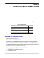
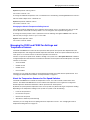
MANAGING FES TEMPERATURE SETTINGS ..................................................................................................5-1
M
ANAGING THE FESX AND FWSX FAN SETTINGS AND
T
EMPERATURE SENSORS .....................................................................................................................5-3
A
BOUT THE TEMPERATURE SENSORS FOR FAN SPEED SWITCHES .........................................................5-3
C
HANGING THE CHASSIS POLLING INTERVAL .........................................................................................5-4
A
DJUSTING TEMPERATURE THRESHOLDS ..............................................................................................5-4
V
IEWING FAN SPEED SWITCHES AND TEMPERATURE THRESHOLDS ........................................................5-5
D
ISPLAYING MANAGEMENT MODULE CPU USAGE .......................................................................................5-5
R
EMOVING MAC ADDRESS ENTRIES ...........................................................................................................5-5
C
HAPTER
6
M
AINTAINING
THE
H
ARDWARE
..................................................................... 6-1
HARDWARE MAINTENANCE SCHEDULE .........................................................................................................6-1
R
EPLACING A POWER SUPPLY ....................................................................................................................6-2
I
NSTALLATION PRECAUTIONS AND WARNINGS ........................................................................................6-2
D
ETERMINING WHICH POWER SUPPLY FAILED ......................................................................................6-2
AC P
OWER SUPPLIES ..........................................................................................................................6-2
DC P
OWER SUPPLIES ..........................................................................................................................6-3
V
ERIFYING PROPER OPERATION ...........................................................................................................6-5
D
ISPLAYING THE STATUS OF THE POWER SUPPLIES ..............................................................................6-5
I
NSTALLING OR REPLACING A 10-GIGABIT ETHERNET MODULE .....................................................................6-6
D
ISASSEMBLING THE CHASSIS ..............................................................................................................6-6
R
EMOVING A 10-GIGABIT ETHERNET MODULE .......................................................................................6-6
I
NSTALLING A 10-GIGABIT ETHERNET MODULE ......................................................................................6-7
R
E-ASSEMBLING THE CHASSIS ..............................................................................................................6-7
R
EPLACING A FIBER OPTIC MODULE ...........................................................................................................6-7
R
EMOVING A FIBER OPTIC MODULE ......................................................................................................6-8
I
NSTALLING A NEW FIBER OPTIC MODULE .............................................................................................6-8
C
ABLING A FIBER OPTIC MODULE .........................................................................................................6-9
C
LEANING THE FIBER-OPTIC CONNECTORS .................................................................................................6-9
C
HAPTER
7
H
ARDWARE
S
PECIFICATIONS
....................................................................... 7-1
CHASSIS SPECIFICATIONS ...........................................................................................................................7-2
P
HYSICAL DIMENSIONS .........................................................................................................................7-2
E
NVIRONMENTAL CONSIDERATIONS ......................................................................................................7-2
C
OOLING .............................................................................................................................................7-3
R
EGULATORY COMPLIANCE ..................................................................................................................7-3
W
ARRANTY ..........................................................................................................................................7-3

Foundry Hardware Installation Guide for the FES, FESX, and FWSX
vi © Foundry Networks, Inc. June 2006
PINOUTS AND SIGNALING ......................................................................................................................7-3
C
ABLE SPECIFICATIONS ........................................................................................................................7-5
P
OWER CORDS ....................................................................................................................................7-6
P
OWER SUPPLY SPECIFICATIONS ................................................................................................................7-6
O
VERVIEW ...........................................................................................................................................7-6
K
EY FEATURES .....................................................................................................................................7-7
P
HYSICAL DIMENSIONS AND WEIGHT ....................................................................................................7-7
I
NPUT CONNECTOR ..............................................................................................................................7-8
R
EGULATORY COMPLIANCE ..................................................................................................................7-8
E
NVIRONMENTAL CONSIDERATIONS ....................................................................................................7-10
E
LECTRICAL SPECIFICATIONS .............................................................................................................7-11
A
PPENDIX
8
C
AUTIONS
AND
W
ARNINGS
.......................................................................... 8-1
CAUTIONS ..................................................................................................................................................8-1
W
ARNINGS .................................................................................................................................................8-7

June 2006 © 2006 Foundry Networks, Inc. 1 - 1
Chapter 1
About This Guide
Introduction
This guide describes the following product families from Foundry Networks:
• FastIron Edge Switch (FES) Layer 2/Layer 3 Switch
• FastIron Edge Switch X-Series (FESX) Layer 2/Layer 3 Switch
• FastIron Workgroup Switch X-Series (FWSX) Layer 2 Switch
This guide includes procedures for installing the hardware and configuring essential, basic parameters such as
permanent passwords and IP addresses. The basic software configuration procedures show how to perform
tasks using the CLI. This guide also includes instructions for managing and maintaining the hardware.
This guide applies to the following products, collectively called the FastIron Family of stackable switches:
• FastIron Edge Switch products:
• FastIron Edge Switch 2402
• FastIron Edge Switch 4802
• FastIron Edge Switch 9604
• FastIron Edge Switch 12GCF
• FastIron Edge Switch 2402-POE
• FastIron Edge Switch 4802-POE
• FastIron Edge Switch X-Series products:
• FastIron Edge Switch X424
• FastIron Edge Switch X448
• FastIron Edge Switch X624
• FastIron Edge Switch X648
• FastIron Workgroup Switch X-Series products:
• FastIron Workgroup Switch X424
• FastIron Workgroup Switch X448

Foundry Hardware Installation Guide for the FES, FESX, and FWSX
1 - 2 © 2006 Foundry Networks, Inc. June 2006
NOTE: Except where explicitly mentioned in this manual, the FES2402 and FES2402-POE are similar devices,
and the FES4802 and FES4802-POE are similar devices. For example, the FES2402 and FES2402-POE have
similar network interfaces and port regions. The same is true of the FES4802 and FES4802-POE.
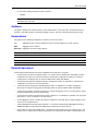
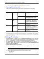
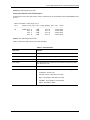
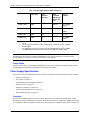
NOTE: This guide contains the terms FastIron Edge Switch (FES), FastIron Edge Switch X-Series (FESX),
and FastIron WorkGroup Switch X-Series (FWSX). Each term refers to a specific set of devices, as shown in
Table 1.1.
What’s Included in This Edition?
This edition describes the following software releases:
• For the FastIron Edge Switch products:
• 03.3.01a
• 03.3.00
• 03.2.00
• 03.1.02
• 03.1.01
• 03.1.00
• 03.0.00
• For the FastIron Edge Switch X-Series products (not including FESX624 and FESX648):
• 02.3.03 (combined FESX/FWSX release)
• 02.3.02 (combined FESX/FWSX release)
• 02.3.01 (combined FESX/FWSX release)
• 02.2.00 (combined FESX/FWSX release)
• 02.1.01
• 02.0.00
• 01.1.00
• 01.0.00
• For the FESX624 and FESX648:
• 02.6.00
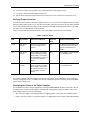
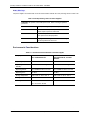
Table 1.1: FastIron Family of Switches
This Name Refers to These Devices
FastIron Edge Switch (FES) FES2402, FES4802, FES9604, FES12GCF,
FES2402-POE, and FES4802-POE
FastIron Edge Switch X-Series (FESX) FESX424, FESX448, FESX624, and FESX648
FastIron Workgroup Switch X-Series
(FWSX)
FWSX424 and FWSX448

About This Guide
June 2006 © 2006 Foundry Networks, Inc. 1 - 3
• For the FastIron Workgroup Switch X-Series products:
• 02.0.00
NOTE: Software releases for the FWSX devices were combined with the FESX software releases starting
with FESX release 02.2.00.
Audience
This guide is designed for network installers, system administrators, and resellers who will install the FastIron
hardware. This guide assumes a working knowledge of Layer 2 and Layer 3 Switching and routing concepts.
Nomenclature
This guide uses the following typographical conventions to show information:
Italic highlights the title of another publication and occasionally emphasizes a word or phrase.
Bold highlights a CLI command.
Bold Italic highlights a term that is being defined.
NOTE: A note emphasizes an important fact or calls your attention to a dependency.
CAUTION: A caution calls your attention to a possible hazard that can damage equipment.
WARNING: A warning calls your attention to a possible hazard that can cause injury or death.
Related Publications
The following Foundry Networks documents supplement the information in this guide.
• Foundry FastIron X-Series Configuration Guide – for X-Series devices (FESX, FSX, and FWSX), provides
configuration procedures for system-level features, and provides configuration information for enterprise
routing protocols including IP, RIP, IP multicast, OSPF, BGP4, VRRP and VRRPE.
• Foundry Switch and Router Installation and Basic Configuration Guide – for FES devices, provides basic
configuration procedures for system-level features.
• Foundry Enterprise Configuration and Management Guide – for FES devices, provides configuration
information for enterprise routing protocols including IP, RIP, IP multicast, OSPF, VRRP and VRRPE.
• Foundry Security Guide – provides procedures for securing management access to Foundry devices and for
protecting against Denial of Service (DoS) attacks.
• Foundry Switch and Router Command Line Interface Reference – for FES devices, provides a list and syntax
information for all CLI commands on Foundry devices.
• Foundry Diagnostic Guide – provides descriptions of diagnostic commands that can help you diagnose and
solve issues on Foundry devices.
• Foundry Management Information Base Reference – contains the Simple Network Management Protocol
(SNMP) Management Information Base (MIB) objects supported on Foundry devices.
• Release Notes for the FastIron Edge Switch – describes features introduced in each software release, lists
features that are supported on the FES, and describes how configuration procedures or defaults differ from

Foundry Hardware Installation Guide for the FES, FESX, and FWSX
1 - 4 © 2006 Foundry Networks, Inc. June 2006
those on other Foundry devices, due to the FastIron Edge Switches’ hardware architecture.
• Release Notes for the FastIron Edge Switch X-Series – describes features introduced in each software
release, lists features that are supported on the FESX, and describes how configuration procedures or
defaults differ from those on other Foundry devices, due to the FastIron Edge Switch X-Series’ hardware
architecture.
• Release Notes for the FastIron Workgroup Switch X-Series – describes features introduced in each software
release, lists features that are supported on the FWSX, and describes how configuration procedures or
defaults differ from those on other Foundry devices, due to the FastIron Workgroup Switch X-Series’
hardware architecture.
How to Get Help
Foundry Networks technical support will ensure that the fast and easy access that you have come to expect from
your Foundry Networks products will be maintained.
Web Access
• http://www.foundrynetworks.com
Email Access
Technical requests can also be sent to the following email address:
• support@foundrynet.com
Telephone Access
• 1.877.TURBOCALL (887.2622) United States
• 1.408.586.1881 Outside the United States
Warranty Coverage
Contact Foundry Networks using any of the methods listed above for information about the standard and extended
warranties.

June 2006 © 2006 Foundry Networks, Inc. 2 - 1
Chapter 2
Product Overview
This chapter contains an overview of the following Foundry Networks product families:
• FastIron Edge Switch® (FES) Layer 2 / Layer 3 Switch
• FastIron Edge Switch X-Series® (FESX) Layer 2 / Layer 3 Switch
• FastIron Workgroup Switch X-Series® (FWSX) Layer 2 Switch
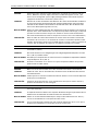
This chapter contains the following information:
Product Overview
The FES, FESX, and FWSX deliver a full complement of standards-based, feature-rich switching and Layer 3
multiprotocol routing capabilities. The extensive feature set supports network requirements ranging from basic
connectivity to multicast-enabled full streaming audio and video applications for converged services such as Voice
over IP (VoIP).
The FES, FESX, and FWSX come in a variety of models, providing an integral range of network connectivity within
the entire enterprise network. These switches provide high 10/100 port density and Gigabit Ethernet uplinks in a
compact, stackable form factor. The FESX and FWSX optionally provide up to two 10-Gigabit Ethernet uplinks.
The FES, FESX, and FWSX models are described below.
• Standard - Provides enterprise network connectivity and server farm support at the wiring closet and edge of
the network. When first shipped from the factory, standard models support full Layer 2 and base Layer 3
Switching.
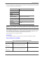
Table 2.1: Chapter Contents
Description See Page
Product overview and the benefits each product offers 2-1
Software features 2-3
POE support overview 2-3
Wireless support overview 2-3
Hardware features and how each major hardware
component functions
2-4

Foundry Hardware Installation Guide for the FES, FESX, and FWSX
2 - 2 © 2006 Foundry Networks, Inc. June 2006
NOTE: The FWSX is a Layer 2 Switch only. It does not support base Layer 3 and full Layer 3.
• Premium (PREM) – Premium devices support full Layer 2 Switching and full Layer 3 multiprotocol routing. All
FES and FESX devices can be upgraded to full Layer 3 multiprotocol routing, at which time they are
considered to be premium devices.
• 12GCF - Provides distribution and backbone connectivity at the Distribution and Core Layers of the enterprise
network. When first shipped from the factory, 12GCF models support full Layer 2 and base Layer 3
Switching.
• POE - Provides enterprise network connectivity and server farm support at the wiring closet and edge of the
network. Also provides electrical power over existing Ethernet cables, supporting the need for integrated
data, voice, and video applications. When first shipped from the factory, POE models support full Layer 2 and
base Layer 3 Switching.
• X-Series - Provides enterprise network connectivity, delivering Gigabit over Copper (GoC) to the desktop,
within the enterprise Distribution Layer, and the service provider data center for high-end servers, cluster
computing, and network-attached storage devices. Also provides the option of a one- or two-port 10 Gigabit
Ethernet module, enabling connectivity within a Metropolitan Area Network (MAN).
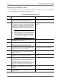
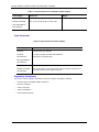
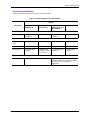
See Table 2.2 for a list of supported configurations.
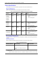
Supported Configurations
Table 2.2 lists the FastIron stackable products and their supported configurations.
NOTE: The device numbers denote the number of ports on the device. For example, the FES2402 has 24 10/
100 ports and 2 Gigabit uplink ports. Likewise, the FESX424, FESX624, and FWSX424 have 4 Gigabit uplink
ports and 24 10/100/1000 ports.
Table 2.2: FastIron Product Family Supported Configurations
Device Standard PREM (Premium) P (POE)
FES2402 X X X
FES4802 X X X
FES9604 X X
FES12GCF X X
FESX424 X
X
a
a.FESX premium devices are available starting in software release 02.0.00.
X
b
b.The FESX424-POE is available starting in software release 02.4.00.
FESX448
X
b
X
a
FESX624 X X
FESX648 X X
FWSX424
c
c.The FWSX424 and FWSX448 devices are Layer 2 Switches only. These devices do not support
base Layer 3 and full Layer 3.
X
FWSX448
c
X

Product Overview
June 2006 © 2006 Foundry Networks, Inc. 2 - 3
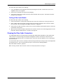
Software Features
Software features differ depending on the software version that is loaded on the device. When first shipped,
Standard and POE devices support full Layer 2 and base Layer 3 Switching. FWSX devices support full Layer 2
Switching only. Premium (PREM) devices support full Layer 2 Switching and full Layer 3 multiprotocol routing. All
FES and FESX devices can be upgraded to premium models, meaning all models can support full Layer 3
multiprotocol routing.
For a complete list of software features supported on the FESX or FWSX, see the release notes or the Foundry
FastIron X-Series Configuration Guide. For a complete list of software features supported on FES, see the FES
release notes.
POE Applications
Foundry’s FES2402-POE, FES4802-POE, and FESX424-POE provide Power over Ethernet, compliant with the
standards described in the IEEE 802.3af specification for delivering in-line power. The 802.3af specification
defines the standard for delivering power over existing network cabling infrastructure, enabling multicast-enabled
full streaming audio and video applications for converged services, such as, Voice over IP (VoIP), WLAN access
points, IP surveillance cameras, and other IP technology devices.
POE technology eliminates the need for an electrical outlet and dedicated UPS near IP powered devices. With
power sourcing devices, such as Foundry’s FES2402-POE and FES4802-POE, power is consolidated and
centralized in the wiring closets, improving the reliability and resiliency of the network. Because POE can provide
power over Ethernet cable, power is continuous, even in the event of a power failure.
For more information about POE and how to configure it on FES devices, see the Foundry Switch and Router
Installation and Basic Configuration Guide. For information about POE and how to configure it on FESX devices,
see the Foundry FastIron X-Series Configuration Guide.
Wireless Applications
You can convert (upgrade) your FastIron Edge Switch to an IronPoint-FES device. Converting your FES to an
IronPoint–FES allows you to run a software image that contains wireless feature support.
To convert your FES to an IronPoint-FES, you need an EEPROM kit, part number FESWLAN. The kit includes a
Dual Inline Package (DIP) key, IronPoint-FES software, upgrade instructions, and other items. Alternatively, you
can order an IronPoint-FES with the EEPROM and wireless software already installed.
You can convert the following FES devices to an IronPoint-FES:
• FastIron Edge Switch 2402
• FastIron Edge Switch 4802
• FastIron Edge Switch 9604
• FastIron Edge Switch 2402–DC
• FastIron Edge Switch 4802–DC
• FastIron Edge Switch 9402–DC
• FastIron Edge Switch 2402-POE
• FastIron Edge Switch 4802-POE
NOTE: You cannot convert the FES12GCF, FastIron Edge Switch X-Series, FastIron Workgroup Switch X-
Series, and FastIron SuperX to an IronPoint–FES device.

Foundry Hardware Installation Guide for the FES, FESX, and FWSX
2 - 4 © 2006 Foundry Networks, Inc. June 2006
The following IronPoint FES devices ship with the firmware required for the wireless features:
• FastIron Edge Switch 2402-WLAN
• FastIron Edge Switch 4802-WLAN
• FastIron Edge Switch 9604-WLAN
• FastIron Edge Switch 2402-WLAN-DC
• FastIron Edge Switch 4802-WLAN-DC
• FastIron Edge Switch 9604-WLAN-DC
• FastIron Edge Switch 2402-POE-WLAN
• FastIron Edge Switch 4802-POE-WLAN
Hardware Features
This section describes the physical characteristics of the Foundry FES, FESX, and FWSX. For details about
physical dimensions, power supply specifications, and pinouts, see the chapter “Hardware Specifications” on
page 7-1.
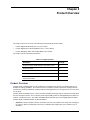
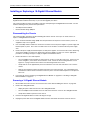
FES2402, FES4802, FES9604
The FastIron Edge Switch (FES) family provides high 10/100 port density and 10/100/1000 Gigabit Ethernet
uplinks in a compact form factor.
• The FES2402 has 24 10/100 ports and two Gigabit uplink ports.
• The FES4802 has 48 10/100 ports and two Gigabit uplink ports.
• The FES9604 has 96 10/100 ports and four Gigabit uplink ports.
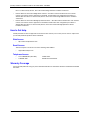
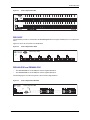
The following figures show the front panels of these FastIron Edge Switches.
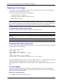
Figure 2.1 FastIron Edge Switch 2402
Figure 2.2 FastIron Edge Switch 4802
Console
PS1
PS2
Power
25C
Act
Lnk
26C
25F 26F
Lnk/
Act
Lnk/
Act
FDX
FDX
1
2
13
14
Console
PS1
PS2
Power
49C
Act
Lnk
50C
49F 50F
Lnk/
Act
Lnk/
Act
FDX
FDX
1
2
13
14
25
26
37
38

Product Overview
June 2006 © 2006 Foundry Networks, Inc. 2 - 5
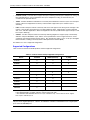
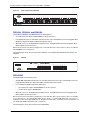
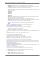
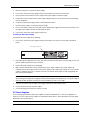
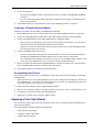
Figure 2.3 FastIron Edge Switch 9604
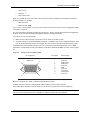
FES12GCF
The FES12GCF provides 12 combination 10/100/1000 Gigabit Ethernet Copper and Fiber ports in a compact form
factor.
Figure 2.4 shows the front panel of the FES12GCF.
Figure 2.4 FastIron Edge Switch 12GCF
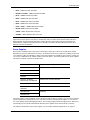
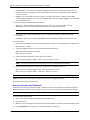
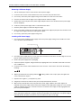
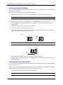
FES2402-POE and FES4802-POE
• The FES2402-POE has 24 10/100 ports and two Gigabit uplink ports.
• The FES4802-POE has 48 10/100 ports and two Gigabit uplink ports.
The following figures show the front panels of these FastIron Edge Switches.
Figure 2.5 FastIron Edge Switch 2402-POE
99C
Act
Lnk
100C
99F 100F
49
50
61
62
73
74
85
86
1
2
13
14
25
26
37
38
Console
PS1
PS2
Power
97C
Act
Lnk
98C
97F 98F
Lnk/
Act
Lnk/
Act
FDX
FDX
CONSOLE
FastIron Edge 12GCF
ACT
LINK
1F 2F
1C
2C
ACT
LINK
11F 12F
11C
12C
POWER
PS1
PS2
ACT
LINK
9F 10F
9C
10C
ACT
LINK
7F 8F
7C
8C
ACT
LINK
5F 6F
5C
6C
ACT
LINK
3F 4F
3C
4C
CONSOLE
POWER
PS1
PS2
ACT
LINK
25F 26F
FastIron Edge 2402 POE
1
2
3
4
5
6
7
8
9
10
11
12
241714 15 16 18 2319 20 21 22131252 3 4 6 117 8 9 101
Link/Act
FDX
Power
13
14
15
16
17
18
19
20
21
22
23
24
25C
26C

Foundry Hardware Installation Guide for the FES, FESX, and FWSX
2 - 6 © 2006 Foundry Networks, Inc. June 2006
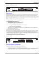
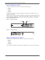
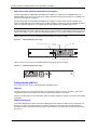
Figure 2.6 FastIron Edge Switch 4802-POE
FESX424, FESX624, and FWSX424
The FESX424, FESX624, and FWSX424 have the following ports:
• 24 Copper ports that support 10/100/1000Base-T RJ-45 connectors
• Four Gigabit Fiber ports for mini-GBIC optical transceivers (also called Small Form Factor Pluggable (SFP)
MultiSource Agreement (MSA)-compliant optical transceivers)
• Optionally, one or two 10-Gigabit Ethernet uplink ports for 10-Gigabit Small Form Factor Pluggable (XFP)
MSA-compliant optical transceivers
Note that one port out of the first four Copper ports or the four Fiber ports can be active at a time (see “FES 10/
100/1000 Mbps Ports” on page 2-9).
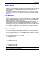
The following figure shows the front panel of the FESX424. The FESX624 and FWSX424 looks similar to the
FESX424.
Figure 2.7 FESX424
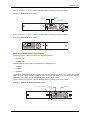
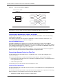
FESX424HF
The FESX424HF has the following ports:
• 20 100/1000 Gigabit Ethernet fiber ports for mini-GBIC optical transceivers (also called Small Form Factor
Pluggable (SFP) Multisource Agreement (MSA)-compliant optical transceivers).
• Four combination Gigabit Copper/Fiber uplink ports:
• The copper ports support 10/100/1000Base-T RJ-45 connectors.
• The fiber ports support 100/1000 SFPs.
• Optionally, one or two 10-Gigabit Ethernet uplink ports for 10-Gigabit Small Form Factor Pluggable (XFP)
MSA-compliant optical transceivers
Note that one port out of the first four Copper ports or the four Fiber ports can be active at a time. For example,
you can use ports 1C – 4C of the Gigabit Copper ports or ports 1 – 4 of the Gigabit Fiber ports. You can use a
combination of fiber and copper uplink ports or all copper or all fiber ports, as needed. For more information, see
see “FESX and FWSX Combination Ports” on page 2-11.
The following figure shows the front panel of the FESX424HF.
241714 15 16 18 2319 20 21 2213
CONSOLE
POWER
PS1
PS2
ACT
LINK
49F 50F
FastIron Edge 4802 POE
37
38
39
40
41
42
43
44
45
46
47
48
484138 39 40 42 4743 44 45 4637
49C
50C
25
26
27
28
29
30
31
32
33
34
35
36
362926 27 28 30 3531 32 33 3425
13
14
15
16
17
18
19
20
21
22
23
24
1
2
3
4
5
6
7
8
9
10
11
12
1252 3 4 6 117 8 9 101
Console
PS2
PS1
Power
1
2
FastIron Edge X424
FastIron Edge X424
1F
Lnk
Act
Lnk
Act
2F
Lnk
Act
3F
Lnk
Act
4F
Lnk
Act
1
2
3
4
1
2
5
6
1
2
7
8
9
10
11
12
115
16
117
18
13
14
19
20
21
22
23
24
Act
Lnk
25/49 26/50

Product Overview
June 2006 © 2006 Foundry Networks, Inc. 2 - 7
Figure 2.8 FESX424HF Front Panel
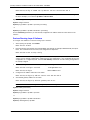
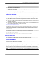
FESX424-POE
Foundry’s FESX424-POE is new in release 02.4.00. Its 10/100/1000 ports provide Power over Ethernet (PoE),
compliant with the IEEE 802.3af specification for delivering power over the LAN. The 802.3af specification
provides the standard for delivering power over existing network cabling infrastructure, enabling multicast-enabled
full streaming audio and video applications for converged services, such as, Voice over IP (VoIP), WLAN access
points, IP surveillance cameras, and other IP powered devices.
For more information about POE and the CLI commands used to configure it, see the Foundry FastIron X-Series
Configuration Guide.
The FESX424-POE has the following ports:
• 20 10/100/1000 ports with RJ-45 copper connectors
• Four combination Gigabit Copper/Fiber uplink ports:
• The copper ports support 10/100/1000BaseT RJ-45 connectors.
• The fiber ports support 10/100/1000 SFPs.
• Optionally, one or two 10-Gigabit Ethernet uplink ports for 10-Gigabit Small Form Factor Pluggable (XFP)
MSA-compliant optical transceivers
The ports numbered from 1 – 24 support POE.
Note that one port out of the first four Copper ports or the four Fiber ports can be active at a time. For example,
you can use ports 1 – 4 of the Gigabit Copper ports or ports 1F – 4F of the Gigabit Fiber ports. You can use a
combination of fiber and copper uplink ports or all copper or all fiber ports, as needed. For more information, see
see “FESX and FWSX Combination Ports” on page 2-11.
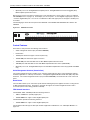
The following figure shows the front panel of the FESX424-POE.
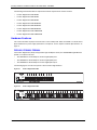
Figure 2.9 FESX424-POE Front Panel
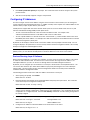
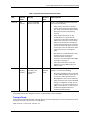
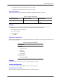
FESX448, FESX648, and FWSX448
The FESX448, FESX648, and FWSX448 have the following ports:
• 48 Copper ports that support 10/100/1000Base-T RJ-45 connectors
• Four Gigabit Fiber uplink ports (1F – 4F) for mini-GBIC optical transceivers (also called Small Form Factor
Pluggable (SFP) Multisource Agreement (MSA)-compliant optical transceivers)
Console
PS2
PS1
Power
FastIron Edge X424HF
Lnk/Act
1C 2C 3C 4C
Act
Lnk
25/49 26/50
1
2
3
4
5
6
7
8
9
10
11
12
13
14
15
16
17
18
19
20
21
22
23
24
Lnk/Act
Console
PS2
PS1
Power
FastIron
on
Edge X424-POE
1F 2F 3F
Lnk Act Lnk Act Lnk Act Lnk Act
4F
Act
Lnk
25/49 26/50
1
2
3
4
5
6
7
8
9
10
11
12
13
14
15
16
17
18
19
20
21
22
23
24
Lnk/
Act
POE Power
Lnk/
Act

Foundry Hardware Installation Guide for the FES, FESX, and FWSX
2 - 8 © 2006 Foundry Networks, Inc. June 2006
• Optionally, one or two 10-Gigabit Ethernet uplink ports for 10-Gigabit Small Form Factor Pluggable (XFP)
MSA-compliant optical transceivers
Note that one port out of the first four Copper ports or the four Fiber ports can be active at a time (see “FES 10/
100/1000 Mbps Ports” on page 2-9). For example, you can use ports 1 –4 of the Gigabit Copper ports or ports 1F
– 4F of the Gigabit Fiber ports. You can use a combination of fiber and copper ports or all copper or all fiber ports,
as needed.
The following figure shows the front panel of the FESX448. The FESX648 and FWSX448 looks similar to the
FESX448.
Figure 2.10 FESX448 Front Panel
Control Features
Each device’s front panel has the following control features:
• Serial management interface (the port labeled Console)
• Reset button
• 10/100 ports with RJ-45 copper connectors (FES only)
• 10/100/1000 ports with RJ-45 copper connectors
• 10/100/1000 ports with mini-GBIC slots for SFP MSA-compliant fiber transceivers
• 100/1000 ports with mini-GBIC slots for SFP MSA-compliant fiber transceivers (FESX424HF)
• Optionally, one or two 10 Gigabit Ethernet ports for XFP MSA-compliant fiber connector(s) (FESX and FWSX
only)
Serial Management Interface (Console Port)
The serial management interface enables you to configure and manage the device using a third-party terminal
emulation application on a directly connected PC. A straight-through EIA/TIA DB-9 serial cable (M/F) ships with
the device. The serial management interface (the port labeled Console) is located in the left corner of the front
panel.
Reset Button
The reset button allows you to restart the system without switching the power supplies off and on or using the CLI
or Web management interface. The button is located to the right of the serial management interface and is
recessed to prevent it from being pushed accidentally.
FES Network Interfaces
The FES2402, 4802, and 9604 provide the following interfaces:
• 10Base-T/100Base-T (10/100) copper ports
• 10/100/1000Base-T copper or Fiber Gigabit uplink ports
The FES12GCF provides the following interfaces:
• 10/100/1000Base-T copper or Fiber Gigabit uplink ports
For information about the type of fiber optic modules supported on FES devices, see “Fiber Optic Modules” on
page 2-15.
Console
PS2
PS1
Power
1
2
FastIron Edge X448
FastIron Edge X448
1F
Lnk
Act
Lnk
Act
2F
Lnk
Act
3F
Lnk
Act
4F
Lnk
Act
1
2
3
4
1
2
5
6
1
2
7
8
9
10
11
12
15
16
17
18
19
20
21
22
23
24
Act
Lnk
25/49 26/50
13
14
25
26
31
3230
27
28
29
33
34
35
36
37
38
39
40
41
42
47
4846
43
44
45

Product Overview
June 2006 © 2006 Foundry Networks, Inc. 2 - 9
FES 10/100 Mbps Ports
The 10/100 copper ports support automatic MDI/MDIX detection, and use auto-sensing and auto-negotiating to
determine the speed (10 Mbps or 100 Mbps) and mode (full-duplex or half-duplex) of the port at the other end of
the link and adjust port speed accordingly. In addition, the 10/100 ports on the FES POE models can detect
802.3af compatible IP devices and provide power accordingly.
For more information about automatic MDI/MDIX detection, see the Foundry Switch and Router Installation and
Basic Configuration Guide.
The 10/100 ports use RJ-45 connectors. For pinout information, see the chapter “Hardware Specifications” on
page 7-1".
The 10/100 Mbps ports on FES devices provide status information using the LEDs listed in Table 2.3.
FES 10/100/1000 Mbps Ports
The 10/100/1000 ports use auto-sensing and auto-negotiating to determine the speed (10 Mbps, 100 Mbps, or
1000 Mbps) and mode (full-duplex or half-duplex) of the port at the other end of the link and adjust port speed
accordingly. 10/100/1000 ports on the devices have the following interfaces:
• RJ-45 copper interface for 10/100/1000Base-T – Cat5 copper cabling
• Mini-GBIC slot for CWDM, 1000Base-BX, LH, LX, or SX – fiber cabling
The copper ports provide auto MDI/MDIX detection (see the Foundry Switch and Router Installation and Basic
Configuration Guide).
One port out of each pair of copper and fiber ports can be active at a time. For example, on the FES12GCF, you
can use either Copper port 10 or Fiber port 10, but not both at the same time. You can use a combination of fiber
and copper ports or all copper or all fiber ports, as needed. On the FES, if you attach both the copper and fiber
connectors for a port to the network, the fiber connector takes precedence over the copper connector and will be
the active connector for the port. Insertion of a fiber mini-GBIC disables the copper connector. To enable a port’s
copper connector, you must remove the port’s fiber mini-GBIC.
The 10/100/1000 Mbps ports on the FES provide status information using the LEDs listed in Table 2.3. The fiber
connectors on the FES devices use the Lnk and Act LEDs located between the mini-GBIC slots for the fiber ports.
The copper connectors use triangular LEDs located in the upper right and left corners of the upper Gigabit copper
connector. The LED on the left side is for the upper copper connector. The LED on the right side is for the lower
copper connector.

Foundry Hardware Installation Guide for the FES, FESX, and FWSX
2 - 10 © 2006 Foundry Networks, Inc. June 2006
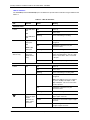
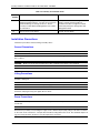
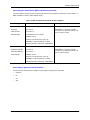
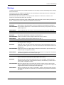
LEDs for FES Ports
The 10/100 Mbps and 10/100/1000 Mbps ports on FES devices provide status information using the LEDs listed in
Table 2.3.
Table 2.3: LEDs for FES Ports
LED Position State Meaning
10/100 Port LEDs
Lnk/Act Left LED above
port
OR
Top LED above
port
On Link is up.
Off Link is down.
Blinking Port is transmitting or receiving.
FDX Right LED
above port
OR
Middle LED
above port
On Full-duplex connection found or
configured.
Off Half-duplex connection or no port
connection exists.
Blinking Collisions are being detected.
Power (POE
devices only)
Bottom LED
above port
(POE devices
only)
On The port is providing in-line power to the
power consuming device, such as a VoIP
phone or other device, that is connected
to the port.
Off The port is not providing in-line power.
10/100/1000 Port LEDs
Lnk/Act Top On Link is up.
Off Link is down.
Blinking Port is transmitting or receiving traffic
FDX Bottom On Full-duplex connection found or
configured.
Note: This LED also is lit if you configure
the port to 10 Mbps full-duplex or 100
Mbps full-duplex. This is true even when
no link is present.
Off Half-duplex connection or no port
connection exists.
Blinking Collisions are being detected.
Upper left
corner of upper
copper
connector for
upper copper
connector
Off No copper port connection exists on
upper copper connector.
Green Copper port is connected on upper copper
connector.
Amber Traffic is being transmitted and received
on upper copper connector.
La page charge ...
La page charge ...
La page charge ...
La page charge ...
La page charge ...
La page charge ...
La page charge ...
La page charge ...
La page charge ...
La page charge ...
La page charge ...
La page charge ...
La page charge ...
La page charge ...
La page charge ...
La page charge ...
La page charge ...
La page charge ...
La page charge ...
La page charge ...
La page charge ...
La page charge ...
La page charge ...
La page charge ...
La page charge ...
La page charge ...
La page charge ...
La page charge ...
La page charge ...
La page charge ...
La page charge ...
La page charge ...
La page charge ...
La page charge ...
La page charge ...
La page charge ...
La page charge ...
La page charge ...
La page charge ...
La page charge ...
La page charge ...
La page charge ...
La page charge ...
La page charge ...
La page charge ...
La page charge ...
La page charge ...
La page charge ...
La page charge ...
La page charge ...
La page charge ...
La page charge ...
La page charge ...
La page charge ...
La page charge ...
La page charge ...
La page charge ...
La page charge ...
La page charge ...
La page charge ...
La page charge ...
La page charge ...
La page charge ...
La page charge ...
La page charge ...
La page charge ...
La page charge ...
La page charge ...
La page charge ...
La page charge ...
La page charge ...
La page charge ...
La page charge ...
La page charge ...
-
 1
1
-
 2
2
-
 3
3
-
 4
4
-
 5
5
-
 6
6
-
 7
7
-
 8
8
-
 9
9
-
 10
10
-
 11
11
-
 12
12
-
 13
13
-
 14
14
-
 15
15
-
 16
16
-
 17
17
-
 18
18
-
 19
19
-
 20
20
-
 21
21
-
 22
22
-
 23
23
-
 24
24
-
 25
25
-
 26
26
-
 27
27
-
 28
28
-
 29
29
-
 30
30
-
 31
31
-
 32
32
-
 33
33
-
 34
34
-
 35
35
-
 36
36
-
 37
37
-
 38
38
-
 39
39
-
 40
40
-
 41
41
-
 42
42
-
 43
43
-
 44
44
-
 45
45
-
 46
46
-
 47
47
-
 48
48
-
 49
49
-
 50
50
-
 51
51
-
 52
52
-
 53
53
-
 54
54
-
 55
55
-
 56
56
-
 57
57
-
 58
58
-
 59
59
-
 60
60
-
 61
61
-
 62
62
-
 63
63
-
 64
64
-
 65
65
-
 66
66
-
 67
67
-
 68
68
-
 69
69
-
 70
70
-
 71
71
-
 72
72
-
 73
73
-
 74
74
-
 75
75
-
 76
76
-
 77
77
-
 78
78
-
 79
79
-
 80
80
-
 81
81
-
 82
82
-
 83
83
-
 84
84
-
 85
85
-
 86
86
-
 87
87
-
 88
88
-
 89
89
-
 90
90
-
 91
91
-
 92
92
-
 93
93
-
 94
94


Foundry Networks FES Guide d'installation
- Catégorie
- Commutateurs réseau
- Taper
- Guide d'installation
dans d''autres langues
Autres documents
-
Digimerge ACCDPS261B Guide de démarrage rapide
-
Lorex 4KHDIP3232B Guide de démarrage rapide
-
-
D-Link DES-1526 Manuel utilisateur
-
 KYLAND Opal5G Guide d'installation
-
Motorola EX-3524 Guide d'installation
-
SMC Networks SMCGS501P Manuel utilisateur
-
Fortinet Switch 124dpoe Manuel utilisateur
-
SMC Networks 8150L2 Manuel utilisateur
-
Netgear FS2105 Manuel utilisateur
