Kenwood X802-5 Le manuel du propriétaire
- Catégorie
- Amplificateurs audio de voiture
- Taper
- Le manuel du propriétaire

X802-5
XM802-5
CLASS D FIVE CHANNEL POWER AMPLIFIER
INSTRUCTION MANUAL
AMPLIFICATEUR DE PUISSANCE 5 CANAUX CLASSE D
MODE D’EMPLOI
AMPLIFICADOR DE POTENCIA DE 5 CANALES CLASE D
MANUAL DE INSTRUCCIONES
Take the time to read through this instruction manual.
Familiarity with installation and operation procedures will help you obtain the best performance from
your new power amplier.
For your records
Record the serial number, found on the back of the unit, in the spaces designated on the warranty card, and in the
space provided below. Refer to the model and serial numbers whenever you call upon your Kenwood dealer for
information or service on the product.
Model X802-5 /XM802-5 Serial number
US Residence Only
Register Online
Register your Kenwood product at www.kenwood.com/usa
B5A-3472-10 / 01 (KN / WN)© 2021 JVCKENWOOD Corporation
248 mm (9-3/4̯)
53 mm
(2-1/16̯)
169 mm (6-5/8̯)
Accessories / Accessoires / Accesorios
Ø4×16 mm
Self-tapping screws
Vis taraudeuses
Tornillo autorroscantes 4Speaker level input cable
Câble d’entrée de niveau d’enceinte
Cable de entrada del nivel de altavoces 1
Dimensions / Dimensions / Dimensiones
KENWOOD
JVCKENWOOD Corporation
■
11
■
@
""
/ @
'W
KIMV00D
@ / " @

Safety precautions
WARNING
To prevent injury or re, take the following precau-
tions:
• Mounting and wiring this product requires skills and
experience. For safety’s sake, leave the mounting and
wiring work to professionals.
• When extending the ignition, battery, or ground wires,
make sure to use automotive-grade wires or other
wires with the range of 5 mm2 (AWG 10) or more to
prevent wire deterioration and damage to the wire
coating.
• To prevent a short circuit, never put or leave any metal-
lic objects (such as coins or metal tools) inside the unit.
• If the unit starts to emit smoke or strange smells,
turn off the power immediately and consult your
KENWOOD dealer.
• Do not touch the unit during use because the sur-
face of the unit becomes hot and may cause burns if
touched.
CAUTION
To prevent damage to the machine, take the follow-
ing precautions:
• Be sure the unit is connected to a 12 V DC power sup-
ply with a negative ground connection.
• Do not open the top or bottom covers of the unit.
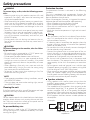
• Do not install the unit in a spot exposed to direct
sunlight or excessive heat or humidity. Also avoid
places with too much dust or the possibility of water
splashing.
• When replacing a fuse, only use a new one with the
prescribed rating. Using a fuse with the wrong rating
may cause your unit to malfunction.
• To prevent a short circuit when replacing a fuse, rst
disconnect the wiring harness.
NOTE
• If you experience problems during installation, consult
your KENWOOD dealer.
• If the unit does not seem to be working right, consult
your KENWOOD dealer.
Cleaning the unit
If the front panel gets dirty, turn o the power and wipe
the panel with a dry silicon cloth or soft cloth.
CAUTION
Do not wipe the panel with a hard cloth or a cloth damp-
ened by volatile solvents such as paint thinner and alco-
hol. They can scratch the surface of the panel and / or
cause the indicator letters to peel o.
To prevent battery rise
When the unit is used in the ACC ON position without
turning the engine ON, it depletes the battery. Use it after
starting the engine.
Protection function
The protection function is activated in the following
situations:
This unit is equipped with a protection function for
protecting this unit and your speakers from various acci-
dents or problems that can occur.
When the protection function is triggered, the power
indicator goes o and the amplier stops operating.
• When a speaker wire may be short-circuited.
• When a speaker output contacts ground.
• When the unit malfunctions and a DC signal is sent to
the speaker output.
• When the internal temperature is high and unit won’t
operate.
Wiring
• Take the battery wire for this unit directly from the bat-
tery. If it’s connected to the vehicle’s wiring harness, it
can cause blown fuses etc.
• If a buzzing noise is heard from the speakers when the
engine is running, connect a line noise lter (optional)
to each of the battery wire.
• Do not allow the wire to directly contact the edge of
the iron plate by using Grommets.
• Connect the ground wire to a metal part of the car
chassis that acts as an electrical ground passing elec-
tricity to the battery‘s negative terminal. Do not turn
the power on if the ground wire is not connected.
• Be sure to install a protective fuse in the power cord
near the battery. The protective fuse should be the
same capacity as the unit’s fuse capacity or somewhat
larger.
• For the power cord and ground, use a vehicle type
(reproof) power wring cord. (Use a power wiring cord
with the range of 5 mm2 (AWG 10) or more.)
• When more than one power amplier are going to be
used, use a power supply wiring wire and protective
fuse of greater current-handling capacity than the total
maximum current drawn by each amplier.
Speaker selection
• Using speakers with smaller input ratings than the
amplier’s output power would result in smoke gener-
ation or equipment failure.
• The impedance of the speakers that are going to be
connected should be 2 Ω or greater (for stereo con-
nections, amplier SUB), or 4 Ω or greater (for bridged
connections). When more than one set of speakers are
going to be used, calculate the combined impedance
of the speakers and then connect suitable speakers to
the amplier.
<Example>
Combined
impedance
■
IA
■
IA
I
40
:
._
___
..,;;..ii
40
I
,
____
---·
80~

MOISTURE
HUMIDITÉ
HUMEDAD
DUST
POUSSIÈRE
POLVO
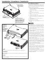
Installation / Installation / Instalación
Installation procedure
Since there are large variety of settings and
connections possible according to applications,
read the instruction manual well to select the
proper setting and connection.
1. Remove the ignition key and disconnect
the negative terminal of the battery to
prevent short circuits.
2. Set the unit according to the intended
usage.
3. Remove the Dressing cover.
4. Connect the input and output wires of the
units.
5. Connect the speaker wires.
6. Connect the power wire, power control
wire and grounding wire following this
order.
7. Install the installation ttings in the unit.
8. Attach the unit.
9. Attach the Dressing cover.
10. Connect the negative terminal of the
battery.
CAUTION
• Do not install in the below locations;
(Unstable location, In a location that inter-
feres with driving, In a location that gets wet,
In a dusty location, In a place that gets hot, In
a place that gets direct sunlight, In a location
that gets hit by hot air)
• Do not install the unit under the carpet.
Otherwise heat build-up occurs and the unit
may be damaged.
• Install this unit in a location which allows
heat to easily dissipate. Once installed, do not
place any object on top of the unit.
• The surface temperature of the amplier will
become hot during use. Install the amplier
in a place where people, resins, and other
substances that are sensitive to heat will not
come into contact with it.
• When making a hole under a seat, inside
the trunk, or somewhere else in the vehicle,
check that there is nothing hazardous on the
opposite side such as a gasoline tank, brake
pipe, or wiring harness, and be careful not to
cause scratches or other damage.
• Do not install near the dashboard, rear tray, or
air bag safety parts.
• The installation to the vehicle should securely
fasten the unit to a place in which it will not
obstruct driving. If the unit comes off due
to a shock and hits a person or safety part, it
may cause injury or an accident.
• After installing the unit, check to make sure
that electrical equipment such as the brake
lamps, turn signal lamps and windshield wip-
ers operate normally.
Installation board, etc.
(thickness: 15 mm or more)
Tableau d’installation, etc.
(épaisseur: 15 mm ou plus)
Tablero de instalación, etc.
(grosor: 15 mm o más)
Parts included
Pièces comprises
Partes incluidas
Dressing cover
Enjoliveur
Cubierta de adorno
XM802-5
Protective
cover
Couvercle de
protection
Cubierta
protectora
Cap
Capuchon
Tapa
NOTE
After wiring, x the protective cover securely with screws and washers.
REMARQUE
Après le câblage, xez fermement le couvercle de protection avec des vis et
des rondelles.
NOTA
Después de realizar el cableado, je rmemente la cubierta protectora con
tornillos y arandelas.
r
■
[A
Ji~~~
..............
;if---------

AFTER MARKET
HEAD UNIT
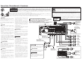
Connections / Raccordements / Conexiones
WARNING Remove the ignition key and disconnect the negative terminal of the battery to prevent short circuits.
AVERTISSEMENT Retirer la clé de contact et débrancher la borne négative de la batterie pour éviter les court-circuits.
ADVERTENCIA
Retire la llave de encendido y desconecte el terminal negativo de la batería para evitar cortocircuitos.
In a computer-equipped vehicle, when you remove the terminal of the battery, the memory may disappear, or a defect may occur in
the electrical system of the vehicle. Consult your dealer for further details.
Dans un véhicule équipé d’un ordinateur, lorsque vous retirez la borne de la batterie, la mémoire peut disparaître ou un défaut peut se
produire dans le système électrique du véhicule. Consultez votre revendeur pour de plus amples détails.
En un vehículo equipado con ordenador, cuando extrae el terminal de la batería, la memoria puede desaparecer o puede producirse un
defecto en el sistema eléctrico del vehículo. Consulte a su proveedor para obtener más detalles.
Battery
Batterie
Batería
Ground wire
Câble de masse
Cable de masa
Battery wire
Câble de la batterie
Cable de la batería
Protective fuse
Fusible de protection
Fusible de protección
Lead terminal
Cosse pour câble
Terminal de cable
WARNING
Particular attention must be given to making
good electrical contact at the amplier-out-
put and speaker terminals.
Poor or loose connections can cause spark-
ing or burning at the terminals because of
the very high power that the amplier can
deliver.
CAUTION
• If sound is not output normally, imme-
diately turn power off and check
connections.
• Be sure to turn the power o before chang-
ing the setting of any switch.
• If the fuse blows, check wires for shorts,
then replace the fuse with one of the same
rating.
• Check that no unconnected wires or con-
nectors are touching the car body. Do not
remove caps from unconnected wires or
connectors to prevent short circuits.
• Connect the speaker wires to appropriate
speaker connectors separately. Sharing the
negative wire of the speaker or grounding
speaker wires to the metal body of the car
can cause this unit to fail.
• After installation, check that the brake
lamps, turn signal lamps and windshield
wipers work properly.
AVERTISSEMENT
Veillez à ce que le contact électrique à la
sortie de l’amplificateur et aux prises des
enceintes soit bien établi.
Un mauvais branchement ou un branche-
ment lâche peut causer des étincelles ou un
réchauement des prises du fait de la très
grande puissance de l’amplicateur.
ATTENTION
• En cas d’anomalie, mettre immédiatement
l’appareil hors tension et vérier tous les
raccordements.
• Veiller à mettre l’appareil hors ten-
sion avant de changer la position des
commutateurs.
• Si le fusible saute, vérier si les câbles ne
sont pas court-circuités, et remplacer
le fusible par un autre fusible de même
capacité nominale.
•
Vérier qu’aucun câble ou connecteur non
raccordé ne touche la carrosserie de la
voiture. Ne pas retirer les capuchons des
câbles ou connecteurs non raccordés an
d’éviter tout courtcircuit.
• Raccorder séparément les câbles de haut-
parleur aux connecteurs de haut-parleur
appropriés. La mise en commun du câble
négatif d’un haut-parleur ou des fils de
masse des haut-parleurs à la carrosserie
métallique de la voiture pourrait rendre
l’appareil inopérant.
• Après l’installation, vérier que les voyants
de frein, les clignotants et les essuie-glace
fonctionnent correctement.
ADVERTENCIA
Debe ponerse especial atención para que se
haga un buen contacto eléctrico en la salida
del amplicador y en los terminales de los
altavoces.
Las conexiones mal hechas o las conexiones
ojas pueden causar chispas o quemaduras
en los terminales debido a la potencia muy
alta que puede suministrar el amplicador.
PRECAUCIÓN
• Si el sonido no sale normalmente, desco-
necte inmediatamente la alimentación y
compruebe las conexiones.
• No se olvide de desconectar la alimenta-
ción antes de cambiar el ajuste de cual-
quier conmutador.
• Si el fusible se quema, compruebe que no
haya un cortocircuito en los cables, luego
cambie el fusible por uno que tenga el
mismo amperaje.
•
Verifique que ninguno de los cables o
conectores que están sin conectar se
encuentren tocando la carrocería del auto-
móvil. No retire las tapas de los cables o
conectores que están sin conectar para evi-
tar de que se produzcan cortocircuitos.
• Conecte los cables del altavoz a los
conectores adecuados del altavoz separa-
damente. La puesta en contacto de termi-
nales de altavoces distintos, o la conexión
como toma de tierra de los terminales del
altavoz al coche del automóvil, pueden
causar daños a la unidad.
•
Después de la instalación, compruebe que
las lámparas del freno, luces de destello y
limpiaparabrisas funcionar correctamente.
Power control wire; for “RCA INPUT connection”
Câble de commande de l’alimentation; pour «Raccordement RCA INPUT»
Cable de control de alimentación; para “Conexión RCA INPUT”
Power wire and speaker wire connection
Raccordement d’un câble de l’alimentation et d’enceinte
Conexión del cable de alimentación y del altavoz
WARNING
To prevent fire caused by a short in the
wiring, connect a fusible link or breaker
nearby the battery’s positive terminal.
AVERTISSEMENT
Pour éviter tout incendie dû à un court-cir-
cuit, insérer un fusible ou un coupecircuit
à proximité de la borne de la batterie.
ADVERTENCIA
Para evitar incendios producidos por cor-
tocircuitos en el cableado, conecte un
fusible o cortacircuito entre la batería y los
terminales de la batería.
Stereo / Stéréo / Estereofónicas
Right
A.ch Droit
Derecho
Left
A.ch Gauche
Izquierdo
Right
B.ch Droit
Derecho
Left
B.ch Gauche
Izquierdo
Bridged / Pont / Puenteada
A.ch
B.ch
The product with this logo is conformed to Hi-Resolution Audio standard dened by
Japan Audio Society. This logo is used under license from Japan Audio Society.
It is recommended that a car audio system should be congured with all High-Resolution
Audio compatible products from player to speaker to enjoy its high quality sound.
Il est recommandé qu’un système audio de voiture doit être conguré avec tous les produits
compatibles Audio Haute Résolution de lecteur à haut-parleur pour apprécier son son haute
qualité. Se recomienda que el sistema de audio del coche esté congu-
rado con todos los productos compatibles con el audio de alta
resolución, desde el reproductor hasta los altavoces, para disfrutar
su alta calidad de sonido.
Subwoofer (L+R)
Haut-parleur
d'extrême grave
(G+D)
Altavoz de
subgraves (I+D)
Subwoofer (L+R)
Haut-parleur
d'extrême grave
(G+D)
Altavoz de
subgraves (I+D)
IA_
IA_
IA
__
IA
IA
■
■
■
IA
IA
IA
<?
"-------;;-----
11----
,}
__Ji
,---_
-~--=
-~~~
ER OUTPUT
~~~su~••
:~~
;:>~

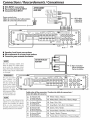
Connections I Raccordements I Conexiones
■
RCA
INPUT connection
■
Raccordement
RCA
INPUT
■
Conexi6n
RCA
INPUT
AFTER
MARKET
HEAD
UNIT
FRONT
REAR
SUB
L~
~ ~
::]
.__
____
R
-t
~ - -~
~
~~
Power control
wire
-
Cable
de
commande
de
l'alimentatio~
..-RCA
cable
Cable
RCA
Cable
RCA
Cable
de
control
de
alimentaci6n _
i <?
FUSE
[
3Q
Ax 3 ]
(@
~
j
□
~~~~@~·•
:
:
■
Speaker level
input
connections
■
Raccordement au niveau haut-parleur
■
Conexi6n
para
entrada
de
altavoz
I NOTE I
Do
not
connect
cables
and
leads
to
both
RCA
cable
input
jacks
and
the
speaker
level
input
terminals simultaneously,
for this may cause malfunction
or damage.
I
REMARQUE
I
Ne pas raccorder
des
cables
ou
conducteurs
a la
fois aux prises
de
sortie
pour
cable
RCA
et
aux prises
d>
entree
de
haut-
FACTORY
INSTALLED
HEAD
UNIT
A.
ch
B.
ch
SUB
~ @ Parts included
Pieces comprises
Partes incluidas
parleu r car l'appa-
L....=JU='.5E================:aE=========:Yu_~~
reil risquera it d'etre
endommage
OU
de
mal fonctionner
I
NOTA
I
No conecte simultaneamente
cables ni
conductores
a las
tomas
de
entrada
de
cables
RCA
o a los
terminales
de
entrada
de
altavoces
porque
podrfa producirse una averfa.
Cable color
of
the
connector/
Couleur
de
cable
du
connecteur /
Color
del
cable del conector
~
A channel
Left
(t)
White /
Blanc
/
Blanco
cg
A
canal
Gauche
A
canal
Izquierdo e
White-Black
/
Blanc-Nair
/
Blanco-Negro
~
A channel
Right
(t)
Gray
/
Gris
/
Gris
ffil
A
canal
Droit
A
canal
Derecho e
Gray-Black
/ Gris-Noir / Gris-Negro
[ID
B channel
Left
(t)
Green
/
Vert
/
Verde
cg
B
canal
Gauche
B
canal
Izquierdo e
Green-Black
/ Vert-Noir / Verde-Negro
[ID
B channel Right
(t)
Purple
/ Violet /
Purpura
ffil
B
canal
Droit
B
canal
Derec
ho
e
Purple-Black
/Violet-Noir / Purpura-Negro

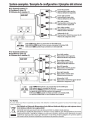
System
examples
I
Exemple
de
configuration
I
Ejemplos
de/
sistema
■
5-channel system (1) Front
left
speaker
Hau~parleuravantgauche
Altavoz
delantero
izquierdo
■
Systeme 5 voies (1)
■
Sistema
de
5 can ales (1)
HEAD
UNIT
Di[]
DiiO
,.....,
'--,
,.....,
'--,
OFF
HPF
O
FF
HPF
e FILT
ER
I])
CJiiD
,.....,
'--,
Front
right
speaker
Haut-parleur
avant
droit
Altavoz
delantero
derecho
Rear left
speaker
Haut-parleur
arriere
gauche
Altavoz
trasero
izquierdo
Rear right
speaker
Haut-parleur
arriere
droit
Altavoz
trasero
derecho
Subwoofer
(L+R)
Haut-parleur
d'extreme
grave
(G+D)
Altavoz
de
subgraves
(l+D)
l§l!ill
em
Select
(;l!ID
when
there
is
connection
to
the
SUB
input.
Selectionnez
(;l!ID lorsqu'il
n'y
a
aucune
connexion
a
l'entree
SUB.
Seleccione
(;l!ID
cuando
haya
conexi6n
a la
entrada
SUB.
INPUT
SELECTOR
....
■
5-channel
system
(2)
■
Systeme 5
voies
(2) Front
left
speaker
Haut-parleur
avant
gauche
Altavoz
delantero
izquierdo
■
Sistema
de
5 canales (2)
For
Turkey
HEAD
UNIT
Front
right
speaker
Haut-parleur
avant
droit
Altavoz
delantero
derecho
DiiO
Rear left
speaker
Haut-parleur
arriere
gauche
Altavoz
trasero
izquierdo
,.....,
'--,
,.....,
'--,
O
FF
H
PF
OFF
HPF
e FILTER
I])
Rear right
speaker
Haut-parleur
arriere
droit
Altavoz
trasero
derecho
•
~
7;.-=.~· •
.
~
-
~
--.
, -
Di[]
,.....,
'--,
l§l!ill
em
INPUT
SELECTOR
Subwoofer
(L+R)
Haut-par
leur
d'e
x
treme
grave
(G+D)
Altavoz
de
subgraves
(l+D)
Select
am
when
there
is
no
c
onnection
to
the
SUB
input.
SUB
output
signal
is
created
by
this
unit.
Selectionnez
am
lorsqu'il n'y a
aucune
connexion
a l'
entree
SUB
.
Le
signal
de
sortie
SUB
est
cree
par
cet
appareil.
Seleccione
am
cuando
no
haya conexi6n a la
entrada
SUB
.
La
serial
de
salida
SUB
se
crea
mediante
esta
unidad
.
Bu
OrOn
28300
sayil1
Resmi
Gazete'de yay1mlanan Atik Elektri
kl
i ve Elektronik
E~yalarin
KontrolO
Yo
netmeli
ge
uygun
ola
rak
Oretilmi~tir.
Eski Elektrik
ve
Elektronik Ekipmanlarm
imha
Edilmesi Hakkmda Bilgi (ayri at1k
toplama
sistem
-
lerini
kullanan
iilkeleri i~in uygulanabilir)
Se
mb
o
llO
(
Oz
e
rind
e
<;:a
rpr i?are
ti
olan
<;:o
p
kutu
su) Orunler
ev
a
t1kl
a
rr
o
la
rak atrlamaz.
Eski elektrik ve elektronik e
kipmanl
ar,
bu
OrOnl
eri ve Orun atrklarrni
ge
ri do
nO
?tOr
eb
ilecek
bi
r
te
siste
degerlendirilm
e
lidir
.
Ya?
adrgrnrz
bol
geye en yak
1n
ge
ri
donu
?
um
tesisinin yerini ogrenm
ek
i
<;:
in yerel
makamla
ra
muracaat e
din
. Uy
gun
geri do
nu
?
um
ve atrk
imh
a
yo
nt
emi
sa
glrgrmrz ve
<;:ev
remiz
Oz
er
in-
de
ki zararlr etkileri onlerken
ka
ynaklarrn
korunm
as
rna
da yardrmcr o
la
ca
kt1
r.

Declaration of Conformity with regard to the
EMC Directive 2014/30/EU
Declaration of Conformity with regard to the
RoHS Directive 2011/65/EU
Manufacturer:
JVCKENWOOD Corporation
3-12, Moriya-cho, Kanagawa-ku, Yokohama-shi,
Kanagawa, 221-0022, JAPAN
EU Representative:
JVCKENWOOD Europe B.V.
Amsterdamseweg 37, 1422 AC Uithoorn,
THE NETHERLANDS
Déclaration de conformité se rapportant à la
directive EMC 2014/30/UE
Déclaration de conformité se rapportant à la
directive RoHS 2011/65/UE
Fabricant:
JVCKENWOOD Corporation
3-12, Moriya-cho, Kanagawa-ku, Yokohama-shi,
Kanagawa, 221-0022, JAPAN
Représentants dans l’UE:
JVCKENWOOD Europe B.V.
Amsterdamseweg 37, 1422 AC Uithoorn, PAYS-BAS
Declaración de conformidad con respecto a
la Directiva EMC 2014/30/UE
Declaración de conformidad con respecto a
la Directiva RoHS 2011/65/UE
Fabricante:
JVCKENWOOD Corporation
3-12, Moriya-cho, Kanagawa-ku, Yokohama-shi,
Kanagawa, 221-0022, JAPAN
Representante en la UE:
JVCKENWOOD Europe B.V.
Amsterdamseweg 37, 1422 AC Uithoorn,
PAÍSES BAJOS
Information on Disposal of Old Electrical and Electronic
Equipment (applicable for countries that have adopted
separate waste collection systems)
Products with the symbol (crossed-out wheeled bin) cannot
be disposed as household waste. Old electrical and electronic
equipment should be recycled at a facility capable of handling
these items and their waste byproducts. Contact your local authority for
details in locating a recycle facility nearest to you. Proper recycling and
waste disposal will help conserve resources whilst preventing detrimental
eects on our health and the environment.
Information sur l’élimination des anciens équipements électriques
et électroniques (applicable dans les pays qui ont adopté des sys-
tèmes de collecte sélective)
Les produits sur lesquels le pictogramme (poubelle barrée) est apposé ne
peuvent pas être éliminés comme ordures ménagères. Les anciens équi-
pements électriques et électroniques doivent être recyclés sur des sites
capables de traiter ces produits et leurs déchets. Contactez vos autorités
locales pour connaître le site de recyclage le plus proche. Un recyclage
adapté et l’élimination des déchets aideront à conserver les ressources et à
nous préserver des leurs eets nocifs sur notre santé et sur l’environnement.
Información acerca de la eliminación de equipos eléctricos y elec-
trónicos al nal de la vida útil (aplicable a los países que hayan
adoptado sistemas independientes de recogida de residuos)
Los productos con el símbolo de un contenedor con ruedas tachado no
podrán ser desechados como residuos domésticos. Los equipos eléctricos
y electrónicos al nal de la vida útil, deberán ser reciclados en instalacio-
nes que puedan dar el tratamiento adecuado a estos productos y a sus
subproductos residuales correspondientes. Póngase en contacto con su
administración local para obtener información sobre el punto de recogida
más cercano. Un tratamiento correcto del reciclaje y la eliminación de
residuos ayuda a conservar los recursos y evita al mismo tiempo efectos
perjudiciales en la salud y el medio ambiente.
For Israel
ʩʨʰʥʥʬʸʯʹʩʩʰʥʸʨʷʬʠʥʩʬʮʹʧʣʥʩʶʬʹʤʴʹʠʬʤʫʬʹʤʸʡʣʡʲʣʩʮ
ʺʣʸʴʥʮʤʴʹʠʳʥʱʩʠʺʫʸʲʮʡʺʥʹʮʺʹʮʹʺʥʰʩʣʮʬ
ʥʩʬʲ Xʭʲ ʤʴʹʠ ʧʴ ʯʥʮʩʱʤ ʭʲ ʭʩʸʶʥʮ ʪʩʬʹʤʬ ʯʺʩʰ ʠʬ
ʯʹʩ ʩʰʥʸʨʷʬʠʥ ʩʬʮʹʧ ʣʥʩʶ ʸʦʧʮʬ ʹʩ ʤʬʩʢʸ ʺʩʺʩʡ ʤʴʹʠʫ
ʥʸʶʭʤʬʹʩʠʥʥʬʤʩʸʶʥʺʡʥʤʬʠʫʭʩʨʩʸʴʡʬʴʨʬʬʢʥʱʮʤʯʷʺʮʡ
ʸʥʦʧʩʮʤʯʷʺʮʺʥʣʥʠʭʩʨʸʴʺʬʡʷʬʺʩʮʥʷʮʤʺʥʹʸʤʭʲʸʹʷ
ʸʮʹʬ ʥʸʦʲʩ ʭʩʺʥʠʰ ʤʴʹʠʬ ʤʫʬʹʤʥ ʸʥʦʧʩʮ ʭʫʩʬʠ ʡʥʸʷʤ
ʤʡʩʡʱʤʬʲʥʥʰʺʥʠʩʸʡʬʲʺʥʩʬʩʬʹʺʥʲʴʹʤʲʥʰʮʬʥʭʩʡʠʹʮ
For U.S.A.
FCC CAUTION
Changes or modications not expressly approved by the party responsible for compliance could void the user’s authority to operate the equipment.
NOTE: This equipment has been tested and found to comply with
the limits for a Class B digital device, pursuant to part 15 of the FCC
Rules. These limits are designed to provide reasonable protection
against harmful interference in a residential installation. This equip-
ment generates, uses and can radiate radio frequency energy and,
if not installed and used in accordance with the instructions, may
cause harmful interference to radio communications. However, there
is no guarantee that interference will not occur in a particular instal-
lation. If this equipment does cause harmful interference to radio
or television reception, which can be determined by turning the
equipment o and on, the user is encouraged to try to correct the
interference by one or more of the following measures:
— Reorient or relocate the receiving antenna.
— Increase the separation between the equipment and receiver.
— Connect the equipment into an outlet on a circuit dierent from
that to which the receiver is connected.
— Consult the dealer or an experienced radio /TV technician for help.
Supplier’s Declaration of Conformity
Trade Name: KENWOOD
Products: CLASS D FIVE CHANNEL
POWER AMPLIFIER
Model Name: X802-5/XM802-5
Responsible Party: JVCKENWOOD USA CORPORATION
2201 East Dominguez Street,
Long Beach, CA 90810, U.S.A.
PHONE: 310 639-9000
THIS DEVICE COMPLIES WITH PART 15 OF THE FCC RULES. OPER-
ATION IS SUBJECT TO THE FOLLOWING TWO CONDITIONS:
(1) THIS DEVICE MAY NOT CAUSE HARMFUL INTERFERENCE,
AND
(2) THIS DEVICE MUST ACCEPT ANY INTERFERENCE RECEIVED,
INCLUDING INTERFERENCE THAT MAY CAUSE UNDESIRED
OPERATION.
X802-5 only / X802-5 uniquement / X802-5 solamente
Declaration of Conformity with regard to the Electromagnetic Compatibility Regulations 2016 (S.I.
2016/1091)
Declaration of Conformity with regard to the Restriction of the Use of Certain Hazardous
Substances in Electrical and Electronic Equipment Regulations 2012 (S.I. 2012/3032)
Manufacturer:
JVCKENWOOD Corporation
3-12, Moriya-cho, Kanagawa-ku, Yokohama-shi, Kanagawa, 221-0022, JAPAN
UK Importer:
JVCKENWOOD U.K. Limited
First Floor, Gleneagles, the Belfry, Colonial Way, Watford, Hertfordshire WD24 4WH, UNITED KINGDOM
For Europe/ Pour l’Europe / Para Europa
X802-5 only /
X802-5 uniquement /
X802-5 solamente
CE
~
UK
CA
-

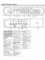
Controls I Contra/es I Contra/es
1 2 3 4 5 6 7
@
INPUT
BASS BOOST
LPF
HPF
SENSITIVITY
(VJ
LEVEL[dB)
FREGUENCY[Hz]
FREGUENCY(Hz
]
D
Isl
IEl!EI
IEl!EI
IEl!EI
D
Isl
1 1
0.5
3(mf
21
□□
.
1~0
1<,0
190
2.
2 .
p.5 fl·
3·
• 1• •
ad
4 ·
o.:3
@ 5
0.2
D
18
50
200
50
200
50
200
@
(MIN]
1MAx1
(M
INI
(MAXltu=JIMINJ
IMAX)
(JU
[Ju
10
The
unit
is
a S-channel
amplifier
incorporating
2
stereo
amplifi-
ers
and 1 monaural amplifier
in
a
single body.
The
stereo
amplifier
on
one
side is called
amplifier
A,
while
the
one
on
the
other side
is
amplifier
B.
The monaural amplifi-
er
is
called the amplifier SUB. This
unit
is compatible with a large va-
riety
of
systems by combining
the
switches and functions described
in the following.
G)
Fuse (30 Ax 3)
I
NOTE
I
If you can't find
the
specified capaci
ty
fuse at
your
s
tore
etc.,
consult
your
KENWOOD
dealer.
@ Battery terminal (POWER IN
BATT.)
® Power control terminal
(P.CON)
Controls
th
e
unit
ON/O
FF.
© Ground terminal (GND)
@
SPEAKER
OUTPUT terminals
(A
.
ch/
B.
ch)
• Stereo connections:
When you wish
to
use
the
unit
as
a
stereo
amplif
ier, stereo connections
are used. The speakers
to
be
con-
nected should have
an
impedance
of
20
or greater. When multiple spea
k-
ers are
to
be connected, ensure
that
the
combined
impedance
is
20
or
greater for each channel.
•
Br
i
dged
connections:
When you wish
to
use
the
unit
as
a
hi
gh-output
amplifier, bridged con-
nections
are
used. (Make connections
to
the
LEFT
channel ® and the
RIGHT
channel 0 S
PE
AKER
OUTPUT
termi
-
nals.) The speakers
to
be connected
~
' ---,
~
' ---,
~'
---,
11m
I
Dial
O
FF
HPF
OF
F
HPF
INPVT
SELECTOR I'll FIL
TER
la)
@
11
12
13
14
15
should have
an
i
mp
edance
of
4 0
or
greater. When
mult
iple speakers
are
to
be connected, en
su
re
that
the
com-
bined impedance is 4 0
or
greater.
@
SPEAKER
OUTPUT terminals
(SUB)
As
this unit accepts speakers
with
a
minimum impedance
of
2 ohms, con-
nect speakers
with
2-ohm
or
higher
impedance
to th
ese terminals.
(J)
SP
LEVEL
INPUT terminal
The
output
from
the
FACTORY
INS
TA
LLED
HEAD UNIT
up
to 50 W
can
be
input.
The
power
is
turned
on
and
off
as
the
un
it detects
input
signal (SIGNAL
SE
NSING TURN-ON).
Therefore
it
is
not
necessary
to
con-
nect the power control wi
re.
@
REMOTE
terminal (SUB)
(for separately available
part
KCA-RC01A)
This terminal is an exclusive terminal
for a con
tr
oller
to
adjust
the
volume
of
the
SUB
output.
® LINE IN terminal (A.ch/B.ch/
SUB)
@INPUT SENSITIVITY control
(A.ch/B.ch/SUB)
Set
this
con
tr
ol
accord
i
ng
to
the
pre-output
level
of
the
HE
AD
UN
IT
connected wi
th
this uni
t.
I NOTE I
For
the
pre-output
level, refer
to
the
"Speci
fications"
in
the
instruction
manual
of
the
HE
AD
UN
I
T.
@ INPUT
SELECTOR
switch
Set
this switch according
to
the
con-
nection
with
th
is unit.
• A B position:
Se
l
ect
"A
B"
when
there
is
no
connection
to
the
SUB
input.
SUB
out-
put
signal
is
created
by
th
is unit.
•
SUB
position:
Select
"SUB
" when there is connection
to
the
SUB
input.
@
BASS
BOOST
LEVEL
control
(SUB)
Sets
the
low
frequency
level
to
be
compensated.
@
LPF
FREQUENCY control (SUB)
This control adjusts
the
frequency
band
output
from
th
is unit.
@
FILTER
switch (
A.ch/B
.
ch)
This
sw
itch al
low
fil
te
r
ing
of
the
speaker output signals.
• HPF (High-
Pass
Filter) position:
The filter outputs
th
e band of higher
frequenci
es
than
the
frequency set
wi
th
the "
HP
F
FREQUENCY"
contro
l.
• OFF position:
The entire
bandw
i
dth
is
output
with-
out
filtering.
@ HPF FREQUENCY control
(A.ch/
B.ch)
This con
tr
ol
ad
justs
the
frequency
band
output
from
th
is unit.
@ Power indicator
When
the
power
is
turned
on
,
th
e
Power indicator lights.
8 9
@
~
KENWOOO
@
16

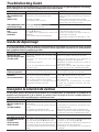
Troubleshooting Guide
What might appear to be a malfunction in your unit may just be the result of slight misoperation or miswiring.
Before calling service, rst check the following table for possible problems.
PROBLEM POSSIBLE CAUSE SOLUTION
No sound.
(No sound from one
side.)
(Blown fuse.)
• Input (or output) cables are disconnected.
• Protection circuit may be activated.
• Volume is too high.
• The speaker cord is shorted.
• Connect the input (or output) cables.
• Check connections by referring to “Protection
function”.
• Replace the fuse and use lower volume.
• After check the speaker cord and xing the
cause of the short, replace the fuse.
The output level is too
small (or too large). • The input sensitivity adjusting control is not
set to the correct position. • Adjust the control correctly referring to “Con-
trols”.
The sound quality is
bad.
(The sound is
distorted.)
•The speakers wire are connected with
wrong/ polarity.
• A speaker wire is pinched by a screw in the
car body.
• The switches may be set improperly.
• Connect them properly checking the /
of the terminals and wires well.
• Connect the speaker wire again so that it is
not pinched by anything.
• Set switches properly by referring to “Con-
trols”.
Guide de dépannage
Ce qui peut apparaître comme un mauvais fonctionnement de votre appareil n’est peut-être que le résultat
d’une mauvaise opération ou d’une mauvaise connexion. Avant d’appeler un centre de service, vériez d’abord
dans le tableau suivant les problèmes possibles.
PROBLEME CAUSE POSSIBLE SOLUTION
Absence de sons.
(Pas de son d’un côté)
(Fusible grillé)
•Les câbles d’entrée (ou de sortie) sont
débranchés.
•Le circuit de protection peut être
actionné.
• Le volume est trop fort.
• Les ls de raccordement d’enceinte sont
en court-circuit.
• Brancher les câbles d’entrée (ou de sortie).
• Vérier les raccordements en se reportant au
paragraphe «Fonction de protection».
• Remplacez le fusible et utilisez un niveau de
volume plus faible.
• Après avoir vérié le câble d’enceinte et réparé
la cause du court-circuit, remplacez le fusible.
Niveau de sortie trop
faible (ou trop fort). •
La commande de réglage de la sensibilité d’en-
trée n’est pas amenée sur la bonne position.
• Faire le réglage correctement en se reportant
aux indications données en «Contrôles».
La qualité sonore est
mauvaise.
(Le son est distordu.)
• Les câbles de haut-parleur ont été raccor-
dés en inversant la polarité/.
• Un câble de haut-parleur est pincé par
une vis dans le châssis de la voiture.
• Les commutateurs ne sont peut-être pas
positionnés comme il convient.
• Raccorder correctement en respectant les indi-
cations et des bornes et des câbles.
• Rebrancher le câble de haut-parleur en évitant
tout pincement
•Positionner les commutateurs en tenant
compte des indications fournies aux para-
graphes «Contrôles».
Guía para la solución de averías
Lo que podría parecer una falla de funcionamiento de su unidad podría ser simplemente el resultado de un
pequeño error de operación o de un defecto de conexión. Antes de acudir al servicio, verique primero el
siguiente cuadro sobre los problemas que se podrían presentar.
PROBLEMA CAUSA POSIBLE SOLUCION
No hay sonido.
(No hay sonido de un
lado.)
(Fusible fundido)
• Los cables de entrada (o salida) están des-
conectados.
• El circuito de protección puede estar acti-
vado.
• El volumen está demasiado alto.
• El cable del altavoz está cortocircuitado.
• Conecte los cables de entrada (o salida).
• Compruebe las conexiones consultando “Fun-
ción de protección”.
• Reemplace el fusible y utilice volumen bajo.
• Después de revisar el cable del altavoz y arreglar
la causa del cortocircuito, reemplace el fusible.
El nivel de salida está
muy bajo (o muy alto) • El control de ajuste de sensibilidad de
entrada no está en la posición correcta. • Ajuste bien el control consultando en “Contro-
les”.
La calidad del sonido
es mala.
(El sonido está
distorsionado.)
• Los cables de los altavoces están conecta-
dos con las polaridades /invertidas.
• Un cable de altavoz está pellizcado por
un tornillo de la carrocería del automóvil.
• Los conmutadores pueden estar mal ajus-
tados.
• Conéctelos correctamente asegurándose bien
de cuáles son los terminales y.
• Vuelva a conectar los cables de los altavoces de
forma que no queden pellizcados.
•Ponga bien los conmutadores consultando
“Controles”.
I I
I I
I I

Spécifications
Les spécifications sont sujettes à changements sans
notication.
Section audio
Puissance de sortie nominale (+B = 14,4 V)
Stéréo (4 Ω)+SUB (4 Ω)
....................................50 W×4 (20 Hz–20 kHz, ≤ 1,0% THD) +
300 W (20 Hz–200 Hz, ≤ 1,0% THD)
Stéréo (2 Ω)+SUB (2 Ω) .......75 W×4 (1 kHz, ≤ 1,0% THD) +
500 W (100 Hz, ≤ 1,0% THD)
Pont (4 Ω)+ SUB (4 Ω) ........ 150 W×2 (1 kHz, ≤ 1,0% THD) +
300 W (20 Hz–200 Hz, ≤ 1,0% THD)
Impédance d'enceinte........................4 Ω (2 Ω à 8 Ω admissible)
(Connexions en pont: 4 Ω à 8 Ω admissible)
Réponse en fréquence (+0, −3 dB).........................20 Hz–50 kHz
(+0, −3 dB)...........20 Hz–200 Hz (SUB)
Sensibilité d'entrée (RCA) ...................................................0,2 V–5,0 V
Taux de signal / bruit.......................................................................100 dB
Impédance d’entrée.......................................................................... 10 kΩ
Fréquence du ltre passe-bas (−24 dB/ oct.) (SUB)
....................................................................50 Hz–200 Hz (variable)
Fréquence du ltre passe-haut (−12 dB/ oct.) (A.ch / B.ch)
....................................................................50 Hz–200 Hz (variable)
Control d’amplication des basses (40 Hz) (SUB)
............................................................................0– +18 dB (variable)
Général
Tension de fonctionnement.........Batterie de voiture 12 V CC
Courant absorbé.................................................................................... 42 A
Taille d’installation (L ×H×P)..........................248 ×53 ×169 mm
9-3/4× 2-1/16× 6-5/8 pouce
Masse .......................................................................................2,1 kg (4,6 lbs)
Especificaciones
Las especicaciones se encuentran sujetas a cambios
sin previo aviso.
Sección de audio
Salida de potencia nominal (+B = 14,4 V)
Estereofónicas (4 Ω) + SUB (4 Ω)..........................................50 W× 4
(20 Hz–20 kHz, ≤ 1,0% de distorsión armónica total)+
300 W (20 Hz–200 Hz, ≤ 1,0% de distorsión armónica total)
Estereofónicas (2 Ω) + SUB (2 Ω)..........................................75 W × 4
(1 kHz, ≤ 1,0% de distorsión armónica total)+
500 W (100 Hz, ≤ 1,0% de distorsión armónica total)
Puenteada (4 Ω)+ SUB (4 Ω)................................................150 W× 2
(1 kHz, ≤ 1,0% de distorsión armónica total)+
300 W (20 Hz–200 Hz, ≤ 1,0% de distorsión armónica total)
Impedancia de altavoz......................... 4 Ω (2 Ω a 8 Ω permitido)
(Conexiones en puente: 4 Ω a 8 Ω permitido)
Respuesta de frecuencia (+0, −3 dB).....................20 Hz–50 kHz
(+0, −3 dB).......20 Hz–200 Hz (SUB)
Sensibilidad de entrada (RCA) .........................................0,2 V–5,0 V
Relación señal a ruido..........................................................................100 dB
Impedancia de entrada ........................................................................10 kΩ
Frecuencia del ltro pasa bajos (−24 dB/octava) (SUB)
....................................................................50 Hz–200 Hz (variable)
Frecuencia del ltro pasa altos (−12 dB/octava) (A.ch/B.ch)
........................................................................50 Hz–200 Hz (variable)
Control acentuador de graves (40 Hz) (SUB)
............................................................................0– +18 dB (variable)
General
Tensión de funcionamiento ..........Batería de coche de 12 V CC
Consumo..................................................................................................... 42 A
Tamaño de instalación (Anch
×
Alt
×
Prof )....
248× 53× 169 mm
9-3/4× 2-1/16× 6-5/8 pulgada
Peso .....................................................................................2,1 kg (4,6 libras)
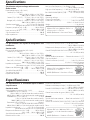
Specifications
Specications subject to change without notice.
Audio section
Rated power output (+B= 14.4 V)
Stereo (4 Ω)+SUB (4 Ω)
..................................50 W × 4 (20 Hz–20 kHz, ≤ 1.0% THD) +
300 W (20 Hz–200 Hz, ≤ 1.0% THD)
Stereo (2 Ω)+SUB (2 Ω).......75 W×4 (1 kHz, ≤ 1.0% THD) +
500 W (100 Hz, ≤ 1.0% THD)
Bridged (4 Ω)+SUB (4 Ω)....150 W×2 (1 kHz, ≤ 1.0% THD)+
300 W (20 Hz–200 Hz, ≤ 1.0% THD)
Speaker impedance.............................4 Ω (2 Ω to 8 Ω allowable)
(Bridged connection: 4 Ω to 8 Ω allowable)
Frequency response (+0, −3 dB)..............................20 Hz–50 kHz
(+0, −3 dB).................20 Hz–200 Hz (SUB)
Input sensitivity (RCA)............................................................0.2 V–5.0 V
Signal to noise ratio.........................................................................100 dB
Input impedance................................................................................ 10 kΩ
Low pass lter frequency (−24 dB / oct.) (SUB)
....................................................................50 Hz–200 Hz (variable)
High pass lter frequency (−12 dB / oct.) (A.ch/ B.ch)
....................................................................50 Hz–200 Hz (variable)
Bass boost control (40 Hz) (SUB)...............0– +18 dB (variable)
General
Operating voltage................................................12 V DC car battery
Current consumption......................................................................... 42 A
Dimensions (W×H×D).....................................248 ×53 ×169 mm
9-3/4× 2-1/16× 6-5/8 inch
Weight.....................................................................................2.1 kg (4.6 lbs)
50 Watts RMS × 4 + 300 Watts RMS× 1 at
4 Ohms and ≤ 1% THD+N
80 dBA (Reference: 1 Watt into 4 Ohms)
50 Watts RMS × 4 + 300 Watts RMS× 1 à
4 Ohms et ≤ 1% THD+N
80 dBA (Référence: 1 Watt dans 4 Ohms)
50 Vatios RMS×4+300 Vatios RMS× 1 a
4 Ohmios y ≤ 1% de distorsión armónica
total+N
80 dBA (Referencia: 1 Vatio en 4 Ohmios)
-
 1
1
-
 2
2
-
 3
3
-
 4
4
-
 5
5
-
 6
6
-
 7
7
-
 8
8
-
 9
9
-
 10
10


Kenwood X802-5 Le manuel du propriétaire
- Catégorie
- Amplificateurs audio de voiture
- Taper
- Le manuel du propriétaire
dans d''autres langues
- English: Kenwood X802-5 Owner's manual
- español: Kenwood X802-5 El manual del propietario