
PN: 1810600301 Spectrum Controls, Inc. Publication 0100267-01B
Installation Instructions
Installing InView Marquee
2706-P9xC2-SC Message Displays
Catalog Number: 2706-P92C2-SC, 2706-P94C2-SC
Inside
Page
Important User Information
2
Overview
3
Wire and Safety Guidelines
3
Description of the InView 92C2-SC and 2706-P94C2-SC Displays
4
Mounting the 2706-P92C2-SC and 2706-P94C2-SC Displays
4
Wiring the 2706-P92C2-SC and 2706-P94C2-SC Displays
6
Specifications
9
2706-P9xC2 Display Language Messaging Format Codes
10
Additional Resources
11
Getting Technical Assistance
12

2 Installing InView Marquee P2706-9xC2-SC Message Displays
Spectrum Controls, Inc. Publication 0100267-01B PN: 1810600301
Important User Information
Solid state equipment has operational characteristics differing from those of electromechanical
equipment. Because of this difference, and also because of the wide variety of uses for solid state
equipment, all persons responsible for applying this equipment must satisfy themselves that each
intended application of this equipment is acceptable.
In no event will Spectrum Controls, Inc. be responsible or liable for indirect or consequential
damages resulting from the use or application of this equipment.
The examples and diagrams in this manual are included solely for illustrative purposes. Because of
the many variables and requirements associated with any particular installation, Spectrum Controls,
Inc. cannot assume responsibility or liability for actual use based on the examples and diagrams.
No patent liability is assumed by Spectrum Controls, Inc. with respect to use of information, circuits,
equipment, or software described in this manual.
Reproduction of the contents of this manual, in whole or in part, without written permission of
Spectrum Controls, Inc., is prohibited.
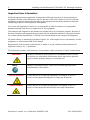
Throughout this manual, when necessary, we use notes to make you aware of safety considerations.
WARNING
WARNING
Identifies information about practices or circumstances that can cause
an explosion in a hazardous environment, which may lead to personal
injury or death, property damage, or economic loss.
NOTE
Identifies information that is critical for successful application and
understanding of the product.
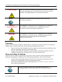
SHOCK HAZARD
Labels may be on or inside the equipment, for example, a drive or
motor, to alert people that dangerous voltage may be present.
BURN HAZARD
Labels may be on or inside the equipment, for example, a drive or
motor, to alert people that surfaces may reach high temperatures.

Installing InView Marquee P2706-9xC2-SC Message Displays 3
PN: 1810600301 Spectrum Controls, Inc. Publication 0100267-01B
AVERTISSEMENT
Actions ou situations risquant de provoquer une explosion dans un
environnement dangereux et d’entraîner des blessures pouvant être
mortelles, des dégâts matériels ou des pertes financières.
NOTE
Informations particulièrement importantes dans le cadre de
l’utilisation du produit.
DANGER
D’ÉLECTROCUTION
Les étiquettes ci-contre, placées sur l’équipement ou à l’intérieur
(un variateur ou un moteur, par ex.), signalent la présence
éventuelle de tensions électriques dangereuses.
RISQUE DE
BRÛLLURE
Les étiquettes ci-contre, placées sur l’équipement ou à l’intérieur
(un variateur ou un moteur, par ex.), indiquent au personnel que
certaines surfaces peuvent atteindre des températures
particulièrement élevées.
Overview
These instructions show you how to mount InView 2706-92C2-SC and 2706-94C2-SC signs with
NEMA Types 4, and 4X enclosures. These signs are intended for indoor use.
Type 4 enclosures are intended to provide a degree of protection against windblown dust
and rain, splashing water, and hose-directed water.
Type 4X enclosures are intended to provide a degree of protection against corrosion,
windblown dust and rain, splashing water, and hose-directed water.
Wire and Safety Guidelines
Install the InView display conforming to all locally in effect, Electrical Safety Requirements for
Employee Workplaces. In addition to the NFPA general guidelines, refer to the following:
Careful cable routing helps minimize electrical noise. Route incoming power to the
module by a separate path from the communication cables.
Wire used for installation must be rated higher than 75° C (167° F) or 15° C (59° F)
above ambient temperature.
NOTE
You can configure your InView Communications module or
Messaging software without having an InView display connected.

4 Installing InView Marquee P2706-9xC2-SC Message Displays
Spectrum Controls, Inc. Publication 0100267-01B PN: 1810600301
Description of the 2706-P92C2-SC and 2706-P94C2-SC Displays
There are two InView C2 models, 2706-92C2-SC and 2706-94C2-SC. These displays provide 10,
user-selectable colors for fonts and bitmaps. The displays provide a 1800 NITs brightness level.
Power consumption is also much lower than the previous models of P9 InView displays. The
resolution is 6.25 mm versus 7.5 mm. You may scroll images and characters from right-to-left, or
left-to-right, depending on the language. The displays comply with NEMA 4 and IP66 housing
standards.
NOTE
If you use the equipment in a manner not specified by Spectrum
Controls, Inc. may impair the protection provided by the equipment.
Mount the sign so that it is easy to disconnect power when servicing.
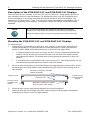
Mounting the 2706-P92C2-SC and 2706-P94C2-SC Displays
To mount the sign:
1. Attach the two sign brackets to a metal post, wall, ceiling, or other surface with sufficient
weight bearing rating. It is preferable that you install the display on metal posts attached
directly to studs. Never install the brackets only on sheetrock with toggle bolts:
If installing directly onto a wall or ceiling, use two 5/16-inch lug bolts and washers per
bracket, screwed at least one-inch into the center of wood studs. The washer must be
snug against the bracket. The bracket must be snug against the sheetrock or other wall
surface.
If a wooden stud is not available in the correct spot, use 3/4 –inch thick plywood or a 3/4-
inch metal backing plate attached to studs to secure the bracket.
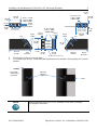
2. Be sure to place the brackets so the bracket flanges face appropriately as shown below. Mount
the brackets the following distance apart (measured from the center of the mounting holes in
each bracket):
3. Mount the sign onto the sign brackets using the two hex bolts supplied.
4. Insert the bolts into the far single holes first, until the desired viewing angle is determined.
Dimensions are shown in mm (in) approximately.
Mounted so flanges are hidden
behind the display
Mounted so flanges are hidden
show on sides of the display
Ceiling or wall
Ceiling or wall
Flanges facing
inwards behind
display
Flanges facing
outwards from
display

Installing InView Marquee P2706-9xC2-SC Message Displays 5
PN: 1810600301 Spectrum Controls, Inc. Publication 0100267-01B
5. Tilt the sign to select a viewing angle.
6. To hold the sign in place, insert the remaining bolts into the desired viewing angle hole on each
bracket.
NOTE
Keep a minimum 2.54 cm (1.0 in.) clearance on all sides of the sign
for adequate ventilation.
38.10
(1.5)
38.10
(1.5)
10.16
(.40)
139.16
(5.40)
8.74 x 17.48
(.344 x .688)
OBROUND
End view,
wall/ceiling
mounted
Ceiling
Wall
Desired
viewing
angle hole
33.78
(1.33)
22.35
(.88)
44.45
(1.75)
44.45
(1.75)
14.53
(0.572
)
10°
193.93
(7.635)
Left
Bracket
07.14
(.281)
117.60
(4.63)
14.53
(0.572)
3.43
(.135)
33.78
(1.33)
8.74 x 17.48
(.344 x .688)
OBROUND
14.53
(0.572)
19.30 (.76)
10.16 (.40) 10.16 (.40)
33.78
(1.33)
10°
07.14
(.281)
193.93
(7.635)
Right
Bracket
07.14
(.28)
22.35
(.88)
33.78
(1.33)
10.16
(.40)
44.45
(1.75)
44.45
(1.75)
8.74 x 17.48
(.344 x .688)
OBROUND
139.16
(5.40)

6 Installing InView Marquee P2706-9xC2-SC Message Displays
Spectrum Controls, Inc. Publication 0100267-01B PN: 1810600301
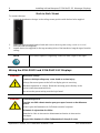
Back-to-Back Mount
To connect the sign:
1. Attach the brackets to the sign in the ceiling mount position with the hex bolts supplied.
2. Match the signs together back-to-back and connect them together using a total of six 5/16”
bolts and nuts (not supplied).
3. Attach chains (not supplied) to the top mounting holes of the bracket to hang the signs from the
ceiling.
NOTE
Use chains capable of supporting 4 times the total weight of the signs.
Wiring the 2706-P92C2 and 2706-P94C2-SC Displays
WARNING
Hazardous voltage.
Contact with high voltage may cause death or serious injury.
Always disconnect power to the InView display prior to servicing.
Maintain separation of circuits. Route the incoming power directly to the
power connections terminal block.
Do not run the power wiring over the logic board.
WARNING
Tension dangereuse.
Toucher un câble a haute tension peut provoquer la mort ou des blessures
graves.
Sortir la prise d'alimentation de l'afficheur avant de le réparer.
Maintenir la séparation des câbles.
Brancher le câble d’alimentation directement au bornier d’alimentation
électrique.
Ne pas faire cheminer le câble d'alimentation le long de la carte

Installing InView Marquee P2706-9xC2-SC Message Displays 7
PN: 1810600301 Spectrum Controls, Inc. Publication 0100267-01B
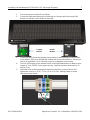
1. Disconnect power to the InView display.
2. Loosen the right-hand drawer by unscrewing its 4 screws until you can pull the
drawer out. Set the screws aside for later step.
3. Connect power conduit through the power drawer conduit opening on the left side
of the drawer. Pull wires through the conduit and wire as shown below. Ensure you
follow all applicable, local, electrical codes for completion of the wiring.
4. The InView Display power terminal block in the right-hand drawer is rated for wire
ranges of 20 to 6 AWG for the power wiring. Strip the electrical wires back 6.35
mm (0.25 in).
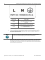
5. Insert the wires into the appropriate terminal connection as shown below and
tighten the screw to 1.47 to 1.7 N-m (13 to 15 in-lbs). Enlarged label is shown
following image below:
Comms
Drawer
Power
Drawer

8 Installing InView Marquee P2706-9xC2-SC Message Displays
Spectrum Controls, Inc. Publication 0100267-01B PN: 1810600301
Wire Color
Wire Name
Black
Line (Hot) connect to L (White
terminal)
White
Neutral connect to N (Blue terminal)
Green
Ground connect to G (Green and
Yellow terminal)
6. If you are installing a Communications Module in the left-hand drawer, install it
now (refer to the 0300289-0n_A0(Users_Guide_InView_COMMS_MODULE)
manual) for additional details.
NOTE
Cable tie locations are supplied within the drawer to help ensure loose
wires are not obstructed by adjacent mechanical obstructions.
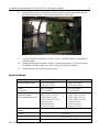
7. Route the Comms cable and tie down the cable as shown below. The cable must be
kept above the board until it is past the slots in the drawer. Individual wires must
also be kept clear of the slots. The InView Comms Module screws must be torqued
to 0.68 N-m (6.0 in-lbs ± 0.100).

Installing InView Marquee P2706-9xC2-SC Message Displays 9
PN: 1810600301 Spectrum Controls, Inc. Publication 0100267-01B
8. Route sixteen inches of the Ethernet cable inside the closure and between the two
terminal blocks as shown. This avoids a tight curve in the cable.
9. Use the 0300289-0n_A0(Users_Guide_InView_COMMS_MODULE) manual to
complete setup.
10. Replace the drawers using the 4 screws. Torque the screws to 1.8 N-m (16 in-lbs)
for NEMA 4 models, and 3 N-m (26.5 in-lbs) for NEMA 4X models.
11. Connect the power wiring to a power source.
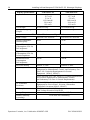
Specifications
Display Specifications
2706-P92C2-SC
2706-P94C2-SC
Active Display Area
39.37 in × 9.84 in
(100 cm × 25 cm)
68.90 in × 9.84 in
(175 cm × 25 cm)
Array/
Pixel pitch
160 × 40 pixels/
6.25 mm pitch
280 × 40 pixels/
6.25 mm pitch
Lines of Text/
Character height/
Max characters per line
40H/1 line/9.9 in/7
32H/1 line/7.25 in/20
20H/2 lines/4.75 in/8
16H/2 lines/3.56 in/20
3 lines/3.0 in/13
4 lines/2.25 in/20
5 lines/1.75 in/24
40H/1 line/9.9 in/12
32H/1 line/7.25 in/35
20H/2 lines/4.75 in/14
16H/2 lines/3.56 in/35
3 lines/3.0 in/13
4 lines/2.25 in/20
5 lines/1.75 in/24
Default Brightness
Setting
1,800 Nits
Colors
10 colors
Viewing Distance
450 ft (137 m)
Character Set
Standard and extended ASCII

10 Installing InView Marquee P2706-9xC2-SC Message Displays
Spectrum Controls, Inc. Publication 0100267-01B PN: 1810600301
Display Specifications
2706-P92C2-SC
2706-P94C2-SC
Physical Dimensions
44.8 in W
15.7 in H
5.2 in D
113.8 mm W
39.9 cm H
132 cm D
74.3 in W
15.7 in H
5.2 in D
188.8 cm W
39.9 cm H
13.2 cm D
Unit Weight
62 lbs/28.13 kg
93.5 lbs/42.41 kg
Packaged (Shipping)
Weight
74 lbs/33.64 kg
111 lbs/50.45 kg
Electrical and Environmental Specifications
Input Voltage
100-264 VAC 50/60 Hz
100-264 VAC 50/60 Hz
Power Consumption
(blank display)
20 W
35 W
Typical Power
Consumption (35% lit)
Full brightness
50 W
90 W
Typical Power
Consumption (35% lit)
Default brightness
35 W
62.5 W
Maximum Power
Consumption
Full brightness
160 W
280 W
Enclosure Rating
NEMA 4 / IP66
NEMA 4 / IP66
UL Safety
UL 61010-2-201 Safety Requirements for Electrical
Equipment for Measurement, Control, and Laboratory Use -
Part 2-201: Particular Requirements for Control
Equipment (NRAQ, NRAQ7)
cUL CAN/CSA C22.2 No. 61010-1-12 (Safety Requirements
for Electrical Equipment for Measurement, Control,
and Laboratory Use–Part 1: General Requirements)
UL Hazardous
Locations
ULH ANSI/ISA–12.12.01–2007 Nonincendive Electrical
Equipment for Use in Class I, Division 2 Hazardous
(Classified) Locations (NRAG, NRAG7)
CE Compliance
EMC Directive 2014/30/EU
Low Voltage Directive 2014/35/EU
Storage Temperature
-40˚ C to 85˚ C (-40˚ F to 185˚ F)
Relative humidity
(operating)
5% to 95% non-condensing

Installing InView Marquee P2706-9xC2-SC Message Displays 11
PN: 1810600301 Spectrum Controls, Inc. Publication 0100267-01B
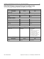
2706-P9xC2 Display Language Message Formatting Codes
The following message formatting codes have been added for the C2 displays:
Mode
Description
ASCII
Hex
Rotate right
A
41
Justification
Description
ASCII
Hex
Right
^^2
IE32
Message Attributes
Description
ASCII
Hex
20High
^Z2
IA32
20Fancy
^Z4
IA34
40High
^Z<
IA3C
40Fancy
^Z=
IA3D
Character Color
Description
ASCII
Hex
RGB Color
^\Zrrggbb
IC5Arrggbb
Where:
rr=ASCII hex value (00 -
FF) for red channel
gg=ASCII hex value (00 -
FF) for green channel
bb=ASCII hex value (00 -
FF) for blue channel
Character Width/Height
Description
ASCII
Hex
Bold
^Q^]01
111D3031

12 Installing InView Marquee P2706-9xC2-SC Message Displays
Spectrum Controls, Inc. Publication 0100267-01B PN: 1810600301
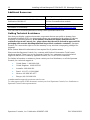
Additional Resources
Resource
Description
InView Communication Module User Manual,
Publication 0300289-05
Provides all setup information for the
InView Communications module.
All other InView Manuals
http://spectrumcontrols.com/InView.htm
Declaration of Conformity
http://spectrumcontrols.com/InView.htm
You can view or download publications at http://www.spectrumcontrols.com
Getting Technical Assistance
Note that your display contains electrostatic components that are susceptible to damage from
electrostatic discharge (ESD). An electrostatic charge can accumulate on the surface of ordinary
wrapping or cushioning material. In the unlikely event that the display should need to be
returned to Spectrum Controls, Inc., please ensure that the unit is enclosed in approved ESD
packaging (such as static-shielding/metallized bag or black conductive container). Spectrum
Controls, Inc. reserves the right to void the warranty on any unit that is improperly packaged for
shipment.
RMA (Return Material Authorization) form required for all product returns.
Please note that Spectrum Controls, Inc. contracts with Rockwell Automation TechConnect
telephone support. There is no cost to Spectrum Controls, Inc. customers to use this technical
support as the service is funded by Spectrum Controls, Inc. for all InView customers.
For further information or assistance, please contact your local distributor, or call the Spectrum
Controls, Inc. technical support at:
United States: 1-440-646-6900
United Kingdom: 01908-635230
Australia: 1800-809-929
Brazil: 011 (55) 11 3619 8800
Mexico: 001-888-365-8677
Europe: (49) 2104 960 630
or send an email to
To order paper copies of this document, contact your local Spectrum Controls, Inc. distributor or
Spectrum Controls sales representative

14 Installing InView Marquee P2706-9xC2-SC Message Displays
Spectrum Controls, Inc. Publication 0100267-01B PN: 1810600301

PN: 1810600301 Spectrum Controls, Inc. Publication 0100267-01B

Spectrum Controls, Inc. Publication 0100267-01B PN: 1810600301
©2016 Spectrum Controls, Inc. All rights reserved.
Specifications subject to change without notice. The
Encompass logo and ControlLogix are trademarks of
Rockwell Automation.
Corporate Headquarters
Spectrum Controls Inc.
1705 132nd Ave NE
Bellevue, WA 98005 USA
Fax: 425-641-9473
Tel: 425-746-9481
Web Site: www.spectrumcontrols.com
E-mail: spectrum@spectrumcontrols
-
 1
1
-
 2
2
-
 3
3
-
 4
4
-
 5
5
-
 6
6
-
 7
7
-
 8
8
-
 9
9
-
 10
10
-
 11
11
-
 12
12
-
 13
13
-
 14
14
-
 15
15


