
Installation
Instructions
BOSCHAPPLIANCES.COM
HEZCMT3050 COFFEE MAKER TRIM KIT

Page. 1
This Bosch
®
appliance is made by
BSH Home Appliances Corporation
1901 Main Street, Suite 600
Irvine, CA 92614
Questions?
1-800-735-4328
www.bosch-home.com/us
We look forward to hearing from you!
Table of
Contents
Safety ...................................................................................... 2
Important Safety Instructions.......................................... 2
Installation with a Warming Drawer........................................ 3
Before You Begin............................................................ 3
General Dimensions........................................................ 3
Cabinet Cutout Dimensions............................................ 3
Flush Install Dimensions.................................................. 4
Installation with a Warming Drawer................................ 4
Stand-Alone Installation.......................................................... 8
Before You Begin............................................................ 8
General Dimensions........................................................ 8
Cabinet Cutout Dimensions............................................ 8
Flush Install Dimensions.................................................. 9
Stand-Alone Installation.................................................. 9
Safety
Definitions
NOTICE: This indicates that damage to the appliance or
property may occur as a result of non-compliance with this
advisory.
Note: This alerts you to important information and/or tips.
9 WARNING
This indicates that death or serious injuries may occur as a
result of non-observance of this warning.
9 CAUTION
This indicates that minor or moderate injuries may occur as a
result of non-observance of this warning.

Page. 2
Safety
IMPORTANT SAFETY
INSTRUCTIONS
READ AND SAVE
THESE INSTRUCTIONS
INSTALLER: Please leave these instructions with this unit
for the owner. Show the owner the location of the circuit
breaker or fuse. Mark it for easy reference.
OWNER: Please retain these instructions for future
reference.
APPLIANCE HANDLING SAFETY
Hidden surfaces may have sharp edges. Use caution when
reaching behind or under appliance.
It is the responsibility of the owner and the installer to
determine if additional requirements and/or standards
apply to specific installations.
ELECTRIC SAFETY
Before you plug in an electrical cord, be sure all controls
are in the OFF position.
For appliances equipped with a cord and plug, DO NOT
cut or remove the ground prong. It must be plugged into
a matching grounding type receptacle to avoid electrical
shock. If there is any doubt as to whether the wall
receptacle is properly grounded, the customer should
have it checked by a qualified electrician.
If required by the National Electrical Code (or Canadian
Electrical Code), this appliance must be installed on a
separate branch circuit.
Be sure your appliance is properly installed and grounded
by a qualified electrician. Installation, electrical
connections and grounding must comply with all
applicable codes.
RELATED EQUIPMENT SAFETY
Remove all tape and packaging before using the
appliance. Destroy the packaging after unpacking the
appliance. Never allow children to play with packaging
material.
Never modify or alter the construction of the appliance.
For example, do not remove leveling legs, panels, wire
covers or anti-tip brackets/screws.
GROUNDING INSTRUCTIONS
This appliance must be grounded. In the event of an
electrical short circuit, grounding reduces the risk of
electric shock by providing an escape wire for the electric
current. This appliance is equipped with a cord having a
grounding wire with a grounding plug. The plug must be
plugged into an outlet that is properly installed and
grounded.
WARNING
When properly cared for, your new appliance has been
designed to be safe and reliable. Read all instructions
carefully before use. These precautions will reduce the
risk of burns, electric shock, fire and injury to persons.
When using kitchen appliances, basic safety precautions
must be followed, including those in the following pages.
WARNING
DO NOT repair or replace any part of the appliance
unless specifically recommended in the manuals.
Improper installation, service or maintenance can cause
injury or property damage. All other servicing should be
done by an authorized servicer.
WARNING
State of California Proposition 65 Warning:
This product can expose you to chemicals including vinyl
chloride, which is known to the State of California to
cause cancer and birth defects or other reproductive
harm. For more information go to
www.P65Warnings.ca.gov.
CAUTION
It is recommended to have two installers to
install the coffee maker. Failure to do so may
result in property damage or personal injury.
WARNING
Improper grounding can result in a risk of electric shock.

Page. 3
Installation with a Warming Drawer
Before You Begin
Trim Kits
Trim kits are designed for use ONLY with the Built-in
Coffee Maker models BCM8450UC.
IMPORTANT: The Built-in Coffee Maker installation
instructions can be found in the Built-in Coffee Maker
Assembly. The coffee maker must be installed according
to the instructions in the Installation Instructions. If the
instructions are not followed, this may result in
unsatisfactory installation or unit performance.
Tools Needed
• Phillips head screwdriver
• Torx T-20 screwdriver
• Measuring tape
• Drill with bits (1/16")
Screws Included with the Coffee Maker Trim Kit
Items Used Included with BCM8450UC Coffee Maker
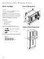
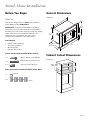
General Dimensions
Cabinet Cutout Dimensions
8 x
#8 x ¾'' Wood Screw (Phillips)
7 x
M4 x 25mm Screw (T20 Torx)
14 x
#10 x ½ Screw (T20 Torx)
1 x
Spacer
4 x
Shims
29¾" (755)
13
¾" (349)
14¾" (374)
17
(449)
11
/16
"
23½" (596)
22" (558)
17
⅞"
(455)
19⅝"
(498)
inches (mm)
28½"
28½"
28½"
(724)
(724)
(724)
23½"
(597)
28⅝"
(727)
inches (mm)

Page. 4
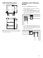
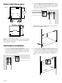
Flush Install Dimensions
NOTE: * Flush installation requires a 5/16'' (8 mm) high x
28½'' (724 mm) wide x 22½'' (571 mm) deep baseplate
underneath the unit body.
Installation with a Warming
Drawer
Mounts above a HWD5051UC Warming Drawer.
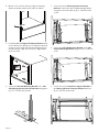
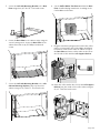
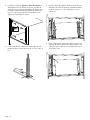
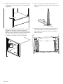
1. Install Warming Drawer according to the Warming
Drawer Installation Instructions.
2. Install the Left Cabinet Mounting Bracket at the top
left of the cabinet opening using two (2) ¾'' Phillips
head wood screws. Ensure the bracket is flush to the
cabinet side and cabinet face.
3. Install the Right Cabinet Mounting Bracket at the top
right of the cabinet opening using two (2) ¾'' Phillips
head wood screws. Ensure the bracket is flush to the
cabinet side and cabinet face.
Top View
Side View
reveal
cleat
29⅛"
(740)
ush
cut-out
height
24½"
(622)
ush inset
depth
¾" (19)
¾" (19)
reveal
cleat
reveal
cleat
1" (25)
1"
(25)
28½" (724)
30¾" (781)
8
(218)
"
9
/16
23½" (622)23½" (622)23½" (622)
*
inches (mm)
dia. 1/16"
1
2
dia. 1/16"
1
2

Page. 5
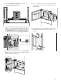
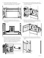
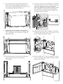
4. Measure 1½'' (38 mm) from top edge of warming
drawer and make mark on both sides of cabinet.
5. Install the Left and Right Side Cabinet Brackets flush
to the cabinet face with two (2) ¾'' Phillips head wood
screws per side. Install side trim mounting bracket so
that the bottom edge of the bracket is aligned with
the pencil mark.
6. Secure the Left Side Mounting Bracket to the Left
Side Warming Drawer Clearance Bracket using three
(3) x
½'' T-20 Torx head screws.
7. Secure the two (2) Warming Drawer Clearance
Brackets to the top of the installed warming drawer
using the outer holes with six (6) ½'' T-20 Torx head
screws.
8. Secure the Left Side Mounting Bracket to the Left
Cabinet Mounting Bracket using one (1) ½'' T-20 Torx
screw.
9. Secure the two (2) Transformer Support Brackets to
the Warming Drawer Clearance Brackets with four
(4) ½'' T-20 Torx head screws.
1½" (38)1½" (38)1½" (38)
dia. 1/16"
1

Page. 6
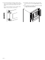
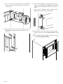
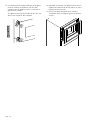
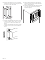
10. Set the Coffee Maker Transformer on top of the
Transformer Support Brackets.
11. Plug the transformer plug into the back of the coffee
maker, as instructed in the Coffee Maker Installation
Instructions. Slide coffee maker in cabinet on top of
the Base Plate and move coffee maker to the left so
the left side is flush with the Left Support Bracket.
12. Open the coffee maker door. Secure the Left Support
Bracket from the inside of the coffee maker using six
(6) x 1'' T-20 Torx head screws.
13. Use a 1'' T-20 Torx screw with spacer (shipped with
coffee maker) to secure the top right corner of the
coffee maker.
14. If the door does not shut smoothly, check to see if the
Door Latch is hitting on the top or bottom or the
receiver.

Page. 7
15. If the latch is hitting on the bottom, pull the coffee
maker out and install the 1mm Shim, included with the
coffee maker, at the bottom left side of the coffee
maker.
If the receiver is hitting on the top, install the 1mm
Shim on the top left of the coffee maker.
16. Reinstall the coffee maker. If the receiver hits again
increase the shim size until the Door Latch no longer
hits.
17. Press the Built-in Coffee Maker Trim Kit into the Left
and Right Side Cabinet Brackets.
1mm 2mm
3mm
4mm

Page. 8
Stand-Alone Installation
Before You Begin
Trim Kits
Trim kits are designed for use ONLY with the Built-in
Coffee Maker models BCM8450UC.
IMPORTANT: The Built-in Coffee Maker installation
instructions can be found in the Built-in Coffee Maker
Assembly. The coffee maker must be installed according
to the instructions in the Installation Manual. If the
instructions are not followed, this may result in
unsatisfactory installation or unit performance.
Tools Needed
• Phillips head screwdriver
• Torx T-20 screwdriver
• Measuring tape
• Drill with bits (1/16")
Screws Included with the Coffee Maker Trim Kit
Items Used Included with BCM8450UC Coffee Maker
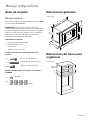
General Dimensions
Cabinet Cutout Dimensions
8 x
#8 x ¾'' Wood Screw (Phillips)
7 x
M4 x 25mm Screw (T20 Torx)
10 x
#10 x ½ Screw (T20 Torx)
1 x
Spacer
4 x
Shims
29¾" (755)
13
¾" (349)
14¾" (374)
17
(449)
11
/16
"
23½" (596)
22" (558)
17
⅞"
(455)
19⅝"
(498)
inches (mm)
28
½
"28
½
"28
½
"
(724)(724)(724)
19
⅞
" – 23
½
"
(504 – 597)
19
⅞
" – 23
½
"
(504 – 597)
19
⅞
" – 23
½
"
(504 – 597)
19
¼
"
(488)
inches (mm)

Page. 9
Flush Install Dimensions
NOTE: * Flush installation requires a 5/16'' (8 mm) high x
28½'' (724 mm) wide x 22½'' (571 mm) deep baseplate
underneath the unit body.
Stand-Alone Installation
1. Install the Left Cabinet Mounting Bracket at the top
left of the cabinet opening using two (2) ¾'' Phillips
head wood screws. Ensure the bracket is flush to the
cabinet side and cabinet face.
2. Install the Right Cabinet Mounting Bracket at the top
right of the cabinet opening using two (2) ¾'' Phillips
head wood screws. Ensure the bracket is flush to the
cabinet side and cabinet face.
3. Measure 1
⅝'' (41 mm) from cabinet base and make
mark on both sides of cabinet.
4. Install the Left and Right Side Cabinet Brackets flush
to the cabinet face with two (2) ¾'' Phillips head wood
screws per side. Install side trim mounting bracket so
that the bottom edge of the bracket is aligned with
mark.
*
Top View
Side View
reveal cleats
20⅛"
(511)
ush
cut-out
height
ush inset
depth
¾" (19)¾" (19)
reveal
cleats
reveal
cleats
1" (25)
1"
(25)
28½" (724)
30" (762)
19
⅞
" – 23
½
"
(504 – 597)
19
⅞
" – 23
½
"
(504 – 597)
19
⅞
" – 23
½
"
(504 – 597)
19
⅞
" – 23
½
"
(504 – 597)
19
⅞
" – 23
½
"
(504 – 597)
19
⅞
" – 23
½
"
(504 – 597)
inches (mm)
dia. 1/16"
1
2
dia. 1/16"
1
2
1⅝" (41)1⅝" (41)1⅝" (41)
dia. 1/16"
1
2

Page. 10
5. Secure the Left Side Mounting Bracket to the Base
Plate using three (3) T-20 x
½'' Torx head screws.
6. Center the Base Plate in the cabinet cavity using the
center locating notch. Secure the Base Plate to the
cabinet floor with six (6) ¾” Phillips head wood
screws.
7. Secure the Left Side Mounting Bracket to the Left
Cabinet Mounting Bracket at the top left of the
cabinet using one (1) T-20 x
½'' Torx head screw.
8. Set the Coffee Maker Transformer behind the Base
Plate. Install and plug transformer according to the
Coffee Maker instructions.
9. Plug the transformer plug into the back of the coffee
maker, as instructed in the Coffee Maker Installation
Instructions. Slide coffee maker in cabinet on top of
the Base Plate and move coffee maker to the left so
the left side is flush with the Left Support Bracket.
10. Open the coffee maker door. Secure the Left Support
Bracket from the inside of the coffee maker using six
(6) x 1'' T-20 Torx head screws.
CCC
LL
dia. 1/16"
1

Page. 11
11. Use a 1'' T-20 Torx screw with the spacer (shipped with
coffee maker) to secure the top right corner of the
coffee maker.
12. If the door does not shut smoothly, check to see if the
Door Latch is hitting on the top or bottom or the
receiver.
13. If the latch is hitting on the bottom, pull the coffee
maker out and install the 1mm Shim, included with the
coffee maker, at the bottom left side of the coffee
maker.
If the receiver is hitting on the top, install the 1mm
Shim on the top left of the coffee maker.
14. Reinstall the coffee maker. If the receiver hits again
increase the shim size until the Door Latch no longer
hits.
15. Press the Built-in Coffee Maker Trim Kit into the left
and right Side Cabinet Brackets.
1mm 2mm
3mm
4mm

Page. 12
Cet appareil électroménager de Bosch
TM
est fait par BSH Home Appliances LtD
1901 Main Street, Suite 600
Irvine, CA 92614
Des questions?
1-800-944-2904
www.bosch-home.com/us
Nous attendons de vos nouvelles!
Table des
Matières
Sécurité................................................................................... 13
Consignes de sécurité importantes ................................ 13
Installation avec tiroir chauffant.............................................. 15
Avant de commencer...................................................... 15
Dimensions générales..................................................... 15
Dimensions du caisson.................................................... 15
Dimensions de l'installation en affleurement.................. 16
Installation avec tiroir chauffant...................................... 16
Installation seule ..................................................................... 20
Avant de commencer...................................................... 20
Dimensions générales..................................................... 20
Dimensions du caisson.................................................... 20
Dimensions de l'installation en affleurement.................. 21
Installation seule ............................................................. 21
Définitions de
Sécurité
NOTICE : Ceci indique que la non-conformité à cet avis de
sécurité peut entraîner des dégâts à l'appareil ou à la propriété.
Note : Ceci vous avertit que d'importantes informations et/ou
conseils sont fournis.
9 AVERTISSEMENT
Ceci indique que le non respect de cet avertissement
peut entraîner des blessures graves, voire la mort.
9 ATTENTION
Ceci indique que le non respect de cet avertissement peut
entraîner des blessures légères ou modérées.

Page. 13
Sécurité
CONSIGNES DE
SÉCURITÉ
IMPORTANTES
LIRE ET CONSERVER
CES CONSIGNES
INSTALLATEUR : Prière de laisser ces instructions
d’installation avec cet appareil à l’intention du
propriétaire. Montrez au propriétaire l'emplacement du
disjoncteur ou du fusible. Identifiez sa position pour
pouvoir le retrouver facilement.
PROPRIÉTAIRE : Prière de conserver ces instructions pour
pouvoir s’y référer ultérieurement.
MANIPULATION SÉCURITAIRE DE L'APPAREIL
Des parties cachées pourraient avoir des rebords
tranchants. Redoublez de vigilance quand vous passez la
main derrière ou sous l'appareil.
Ce sont au propriétaire et à l'installateur qu'il incombe de
déterminer si des exigences ou des codes additionnels
s'appliquent à des installations spécifiques.
SÉCURITÉ ÉLECTRIQUE
Avant de brancher le cordon électrique, vérifiez que
toutes les commandes sont à la position OFF (Arrêt).
NE PAS brancher la cafetière dans la prise murale avant
d'avoir terminé l'installation. Vous éviterez ainsi d'activer
accidentellement la cafetière au cours de l'installation.
Pour les appareils dotés d'un cordon d'alimentation avec
fiche, NE PAS couper ni enlever la broche de mise à la
terre. Pour éviter toute décharge électrique, branchez le
cordon dans une prise de courant correspondante avec
mise à la terre. En cas de doute concernant la mise à la
terre appropriée de la prise murale, le client doit faire
vérifier celle-ci par un électricien qualifié.
Si le National Electrical Code (ou le Code canadien de
l'électricité) l'exige, cet appareil doit être installé sur un
circuit séparé.
Assurez-vous que l'appareil est correctement installé et
mis à la terre par un technicien qualifié. L’installation, les
raccordements électriques et la mise à la terre doivent
être conformes avec tous les codes applicables.
AUTRES CONSIGNES DE SÉCURITÉ DE L'APPAREIL
Retirez tout le ruban et l'emballage avant d'utiliser
l'appareil. Jetez tout l'emballage après avoir déballé
l'appareil. Ne laissez jamais les enfants jouer avec le
matériel d'emballage.
Ne modifiez ou n'altérez jamais la construction de
l'appareil. Par exemple, ne retirez pas les pieds
d'ajustement, les panneaux, les couvre-fils ou les vis ou
supports anti-basculement.
AVERTISSEMENT
Correctement entretenu, votre nouvel électroménager a
été conçu pour être sécuritaire et fiable. Lisez toutes les
instructions attentivement avant l’utilisation. Ces
consignes réduiront le risque de brûlure, d'électrocution,
d’incendie et de blessure pour les personnes utilisant
l'appareil. Lorsque vous utilisez des appareils
électroménagers, il importe de suivre les précautions de
sécurité de base, y compris celles indiquées dans les
pages suivantes.
AVERTISSEMENT
NE PAS réparer ni remplacer toute pièce de l’appareil à
moins que cela ne soit spécifiquement recommandé par
ce manuel. L'installation, l'entretien ou un service
inadéquat pourrait causer des blessures ou des dégâts
matériels. Toute autre réparation devrait être effectuée
par un service d'entretien autorisé.
AVERTISSEMENT
Avertissement relatifs à la Proposition 65 de l'État de
la Californie :
Ce produit vous exposez à des produits chimiques,
comme du chlorure de vinyle, reconnus par l'État de la
Californie comme causant le cancer, des malformations
congénitales ou d'autres effets nocifs sur la
reproduction. Pour de plus amples renseignements,
consulter www.P65Warnings.ca.gov.
MISE EN GARDE
Il est conseillé de faire installer la cafetière
par deux (2) installateurs. Tout manquement à
respecter cette consigne pourrait occasionner
des dégâts matériels ou des blessures.

Page. 14
CONSIGNES DE
SÉCURITÉ
IMPORTANTES
LIRE ET CONSERVER
CES CONSIGNES
INSTRUCTIONS DE MISE À LA TERRE
Cet appareil doit être mis à la terre. En cas de court-circuit
électrique, la mise à la terre réduira le risque de décharge
électrique en offrant au courant électrique un fil
d'évacuation. Cet appareil est équipé d’un cordon ayant
un fil de mise à la terre avec une prise de mise à la terre.
La fiche doit être branchée dans une prise qui a été
installée et mise à la terre de façon conforme.
AVERTISSEMENT
Une mise à la terre inadéquate peut entraîner un risque
d'électrocution.

Page. 15
Installation avec tiroir chauffant
Avant de commencer
Ensembles de finition
Les ensembles de finition sont conçus pour être utilisés
SEULEMENT avec les modèles de cafetière encastrable
BCM8450UC.
IMPORTANT : Les instructions d'installation de la cafetière
encastrable se trouvent dans l'assemblage de la cafetière
encastrable. La cafetière doit être installée en respectant
les instructions dans le manuel d'installation. Si les
instructions ne sont pas respectées, l'installation ou le
rendement de l'appareil pourrait être inadéquat.
Outils requis
• Tournevis à tête Phillips
• Tournevis Torx T-20
• Ruban à mesurer
• Perceuse avec forets (1/16 po)
Vis comprises avec la barrette de finition de la
cafetière :
Articles utilisés inclus avec la cafetière modèle
TCM24RS :
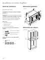
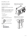
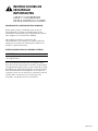
Dimensions générales
Dimensions du caisson
8 x
#8 x ¾'' Vis à bois (Phillips)
7 x
M4 x 25mm Vis (T20 Torx)
14 x
#10 x ½ Vis (T20 Torx)
1 x
Entretoise
4 x
Cales
29¾" (755)
13
¾" (349)
14¾" (374)
17
(449)
11
/16
"
23½" (596)
22" (558)
17
⅞"
(455)
19⅝"
(498)
pouces (mm)
28½"
28½"
28½"
(724)
(724)
(724)
23½"
(597)
28⅝"
(727)
pouces (mm)

Page. 16
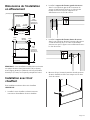
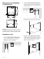
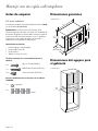
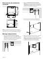
Dimensions de l'installation
en affleurement
REMARQUE : * Une installation en affleurement nécessite
une plaque de base d'une hauteur de 5/16 po (8 mm),
d'une largeur de 28½ po (724 mm) et d'une profondeur
de 22½ po (571 mm) sous la partie principale de l'unité.
Installation avec tiroir
chauffant
Pour installation au-dessus d'un tiroir chauffant
HWD5051UC.
1. Installez le tiroir chauffant conformément aux
instructions d'installation du tiroir chauffant.
2. Installez le support de fixation gauche du caisson
dans le coin supérieur gauche de l'ouverture du
caisson à l'aide de deux (2) ¾ po vis à bois à tête
Phillips. Assurez-vous que le support est en
affleurement avec le côté du caisson.
3. Installez le support de fixation droite du caisson
dans le coin supérieur droit de l'ouverture du caisson
à l'aide de deux (2) ¾ po vis à bois à tête Phillips.
Assurez-vous que le support est en affleurement avec
le côté du caisson.
4. Mesurez 1½ po (38 mm) à partir du rebord supérieur
du tiroir chauffant et faites une marque sur les deux
côtés du caisson.
Vue latérale
Bordure
de cadre
Hauteur de
découpe en
affleurement
Profondeur
intérieure en
affleurement
Bordure
de cadre
Bordure
de cadre
Vue du dessus
29⅛"
(740)
24½"
(622)
¾" (19)¾" (19)
1" (25)
1"
(25)
28½" (724)
30¾" (781)
8
(218)
"
9
/16
23½" (622)23½" (622)23½" (622)
*
pouces (mm)
dia. 1/16"
1
2
dia. 1/16"
1
2
1½" (38)1½" (38)1½" (38)

Page. 17
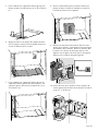
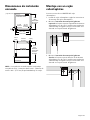
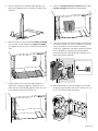
5. Installez les supports gauche et droit du caisson en
affleurement avec le devant du caisson, à l'aide de
deux (2) ¾ po vis à bois à tête Phillips sur chaque côté.
Installez le support latéral de fixation de finition de
façon à ce que le rebord inférieur du support soit
aligné avec la marque au crayon.
6. Fixer solidement le support de fixation gauche à la
plaque de base à l'aide des trois (3) vis Torx T-20 x ½
po..
7. Fixez les deux (2) supports d'espacement du tiroir
chauffant sur le dessus du tiroir chauffant installé à
l'aide de six (6) ½'' vis Torx T-20 dans les trous
extérieurs.
8. Fixer solidement le support de fixation gauche au
support de fixation gauche du caisson dans le coin
supérieur gauche de l'armoire à l'aide d'une (1) vis
Torx T-20 x ½ po.
dia. 1/16"
1

Page. 18
9. Fixez les deux (2) supports de soutien du
transformateur aux supports d'espacement du tiroir
chauffant à l'aide de quatre (4) ½'' vis Torx T-20.
10. Placez le transformateur de la cafetière sur les
supports de soutien du transformateur. Branchez le
transformateur.
11. Brancher la fiche du transformateur dans la section
arrière de la cafetière, conformément aux instructions
d'installation de la cafetière. Glisser la cafetière dans
l'armoire sur le dessus de la plaque de base et la
déplacer vers la gauche de sorte que le côté gauche
affleure avec le support de fixation gauche.
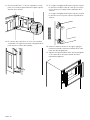
12. Ouvrez la porte de la cafetière. Fixez le support de
soutien gauche de l'intérieur de la cafetière à l'aide de
six (6) x 1 '' T-20 Torx vis.
13. Utiliser une vis Torx T-20 de 1 po avec l'entretoise
(expédiée avec la cafetière) pour fixer solidement le
coin supérieur droit de la cafetière.
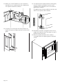
14. Si la porte ne se ferme pas sans heurt, Vérifier si le
loquet de la porte ne frappe pas haut ou le bas de la
gâche.

Page. 19
15. Si le loquet heurte la partie inférieure de la gâche,
retirer la cafetière et installer la cale de 1 mm
(comprise avec la cafetière) sous le coin inférieur
gauche de la cafetière.
Si la gâche heurte le haut, installer la cale de 1 mm
dans le coin supérieur de la cafetière.
16. Réinstaller la cafetière. Si la gâche heurte encore,
augmenter l'épaisseur de la cale jusqu'à ce que le
loquet pénètre sans heurt.
17. Placez l'ensemble de finition de la cafetière
encastrable dans les supports gauche et droit du
caisson.
1mm 2mm
3mm
4mm
La page est en cours de chargement...
La page est en cours de chargement...
La page est en cours de chargement...
La page est en cours de chargement...
La page est en cours de chargement...
La page est en cours de chargement...
La page est en cours de chargement...
La page est en cours de chargement...
La page est en cours de chargement...
La page est en cours de chargement...
La page est en cours de chargement...
La page est en cours de chargement...
La page est en cours de chargement...
La page est en cours de chargement...
La page est en cours de chargement...
La page est en cours de chargement...
La page est en cours de chargement...
-
 1
1
-
 2
2
-
 3
3
-
 4
4
-
 5
5
-
 6
6
-
 7
7
-
 8
8
-
 9
9
-
 10
10
-
 11
11
-
 12
12
-
 13
13
-
 14
14
-
 15
15
-
 16
16
-
 17
17
-
 18
18
-
 19
19
-
 20
20
-
 21
21
-
 22
22
-
 23
23
-
 24
24
-
 25
25
-
 26
26
-
 27
27
-
 28
28
-
 29
29
-
 30
30
-
 31
31
-
 32
32
-
 33
33
-
 34
34
-
 35
35
-
 36
36
-
 37
37


dans d''autres langues
- English: Bosch HEZCMT3050 User manual
- español: Bosch HEZCMT3050 Manual de usuario