Airwell AquaScop AM AQHAS 05-N-2GB Installation and Maintenance Manual
- Taper
- Installation and Maintenance Manual

English
AM AQHAS 05-N-2GB
Part number / Code / Teil Nummer / Codice / Código : 3990666GB
Supersedes / Annule et remplace / Annulliert und ersetzt /
Annulla e sostituisce / Anula y sustituye : AM AQHAS 05-N-1GB
Français EspañolDeutsch Italiano
Dual zone kit
Kit double zone
Doppelbereichs-Bausatz
Kit doppia zona
Kit doble zona
Installation and maintenance manual
Manuel d’installation et de maintenance
Installations- und Wartungshandbuch
Manuale di installazione e di manutenzione
Manual de instalación y de mantenimiento
AM AQHAS 05-N-2
Part number / Code / Teil Nummer / Codice / Código : 3990666
Supersedes / Annule et remplace / Annulliert und ersetzt /
Annulla e sostituisce / Anula y sustituye : AM AQHAS 05-N-1
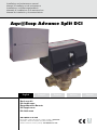
Aqu@Scop Advance Split DCI


INSTALLATION INSTRUCTION
NOTICE D’INSTALLATION
INSTALLATIONSHANDBUCH
ISTRUZIONI INSTALLAZIONE
INSTRUCCIONES DE INSTALACIÓN

2
CONTENTS
1. SAFETY INSTRUCTIONS ............................................................................................................................................. 3
1.1. SAFETY INSTRUCTIONS EXPLANATIONS ........................................................................................................................................................ 3
1.2. INTENDED RECIPIENTS ................................................................................................................................................................................. 3
1.3. REGULATORY COMPLIANCE ......................................................................................................................................................................... 3
1.4. WORKING ON THE INSTALLATION ............................................................................................................................................................... 3
2. INSTALLATION ........................................................................................................................................................... 4
2.1. MIXER VALVE ................................................................................................................................................................................................. 4
2.2. SZSFT OUTLET TEMPERATURE PROBE ............................................................................................................................................................ 5
2.3. CONNECTION BOX ..................................................................................................................................................................................... 6
2.4. ELECTRICAL CONNECTIONS ........................................................................................................................................................................ 6
2.4.1. ELECTRICAL CONNECTIONS - GENERAL DIAGRAM ............................................................................................................................................................. 6
2.4.2. ROUTING THE CABLES ........................................................................................................................................................................................................ 7
2.4.3. DZSFT OUTLET PROBE ......................................................................................................................................................................................................... 7
2.4.4. HEATING CIRCUIT PUMP ..................................................................................................................................................................................................... 7
2.4.5. MIXER VALVE ....................................................................................................................................................................................................................... 8
2.4.6. CONNECT THE KM BUS ...................................................................................................................................................................................................... 9
2.5. S1 ROTARY SWITCH SETTINGS ...................................................................................................................................................................... 9
3. MAINS POWER SUPPLY ............................................................................................................................................ 10
4. COMMISSIONING ................................................................................................................................................... 11
4.1. FILLING / BLEEDING THE INSTALLATION ..................................................................................................................................................... 11
4.2. INSTALLATION CONFIGURATION ............................................................................................................................................................... 11
5. TECHNICAL DATA .................................................................................................................................................... 11
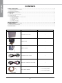
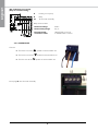
COMPONENT DESCRIPTION QUANTITY
CONNECTION BOX 1
MIXER VALVE 1
DZSFT PROBE 1
POWER SUPPLY CABLE 1
KM BUS CONNECTION CABLE 1
SFT OR BTT PROBE
2 in kit 7ACFH0808
0 in kit 7ACFH0809

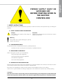
3
POWER SUPPLY MUST BE
SWITCHED OFF
BEFORE STARTING WORK IN
THE ELECTRIC
CONTROL BOX
1. SAFETY INSTRUCTIONS
These safety instructions must be followed scrupulously in order to avoid any risk of personal injury or damage to
property.
1.1. SAFETY INSTRUCTIONS EXPLANATIONS
Warning
This symbol warns against damage to property
and the environment.
Danger
This symbol warns people of the danger of
personal injury.
Comment
Indications preceded by the word "Comment" contain
additional information.
1.2. INTENDED RECIPIENTS
The present manual is intended exclusively for qualified personnel.
² Electrical work must only be carried out by a qualified technician.
1.3. REGULATORY COMPLIANCE
When carrying out any work, you must abide by:
² Accident prevention legislation.
² Environmental protection legislation.
² Professional legislation.
² Current safety legislation.
1.4. WORKING ON THE INSTALLATION
Disconnect the mains power supply to the installation (e.g. at the fuse holder on the electrical connection or at the
mains switch) and then check to ensure the power is disconnected.
Ensure that it is impossible for anyone to restore power to the installation while you are working.
In the case of a gas-fired boiler, shut the gas supply valve cock and block it to prevent any untimely opening.
The dual zone function requires the presence of the SFT heating circuit temperature probe and the BTT
buffer tank temperature probe. Refer to the manual supplied with the probes for installation details.
Comment

4
2. INSTALLATION
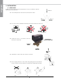
2.1. MIXER VALVE
Install the powered valve on the low temperature circuit in accordance with the
following recommendations:
FLOOR
INLET
Aqu@Scop
Advance Split DCI
FLOOR
OUTLET
OK
NO
NO
² Leave adequate free clearance to fit/remove the motor.
² The valve must be installed horizontally to the motor above the valve axis.
² Install the valve in accordance with the
direction of water flow.
² Installation is easier if the valve motor is removed.
² Do not apply pressure on the motor during fitting/removal operations.
On the contrary, use hand pressure to perform this tightening operation.

5
2.2. SZSFT OUTLET TEMPERATURE PROBE
Fit the probe acting as the outlet probe directly behind the low temperature circuit heating circuit pump,
in accordance with the direction of water flow through the heating water outlet pipe.
If synthetic material pipes are used, install the probe on a metal bridging pipe.
Clean the outlet/inlet pipe down to bare metal.
Heat conducting paste not required.
Do not insulate the probe.
FS
DZSFT
SFT
BTT
B
AB
A

6
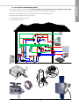
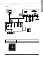
F1 Fuse
S1 Rotary switch
230 V¬ plug
20 Heating circuit pump (not supplied)
40 Mains power supply
52 Mixer valve servo-motor
Very Low Voltage connections
2 Outlet probe
145 BUS KM
The electronic components can be damaged by electrostatic discharges.
Warning
Earth part of the system, such as the heating or water pipes, before commencing work in order to avoid any risk
of electrostatic discharges.
2.3. CONNECTION BOX
Attach the box to the wall.
2.4. ELECTRICAL CONNECTIONS
2.4.1. ELECTRICAL CONNECTIONS - GENERAL DIAGRAM

7
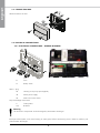
Electrical connection:
Insert plug 2 (outlet probe) into the motor assembly.
2.4.2. ROUTING THE CABLES
Open the motor assembly connection box. Block the unused openings with cable grommets (uncut).
Assembly 1
Cables with a moulded cable clamp (supplied).
Assembly 2
Cables to be provided on site.
2.4.3. DZSFT OUTLET PROBE
For under-floor heating circuits, a monitoring aquastat must be installed to
limit the maximum under-floor heating temperature.
230 V Heating circuit pump
A Heating circuit pump
20 To the motor assembly
230 V Heating circuit pump technical data:
Nominal Amperage 2(1) A
Recommended connection
cable
H05VV-F3G 0.75 mm²
or H05RN-F3G 0.75mm²
Comment
2.4.4. HEATING CIRCUIT PUMP

8
Relay technical data:
Nominal voltage 230V~
Nominal Amperage 2(1) A
Recommended
connection cable
H05VV-F3G 0.75 mm²
or H05RN-F3G 0.75mm²
400 V Heating circuit pump
(Only for wall mounting)
A Heating circuit pump
B Relay
20 To the motor assembly
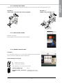
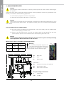
2.4.5. MIXER VALVE
Connect:
² The black wire to the symbol on terminal block 52
² The brown wire to the symbol on terminal block 52
² The blue wire to the N symbol on terminal block 52
Insert plug 52 into the motor assembly

9
Heating circuit on which the
mixer valve intervenes:
Pobes connected Rotary switch position:
Heating circuit with M2 mixer valve Outlet probe "2" (factory default setting)
2.4.6. CONNECT THE KM BUS
2.5. S1 ROTARY SWITCH SETTINGS
The mixer valve regulation module must be connected to the Aqu@Scop Advance Split DCI indoor unit via
the KM BUS.

10
3. MAINS POWER SUPPLY
Non-compliant electrical installations can lead to personal injuries from electric shocks and damage to
the appliance.
Danger
Connect the mains power supply and install the necessary electrical protection measures (e.g. differential circuit
breaker) in accordance with the following regulations:
² Local electricity supplier's connection requirements.
² Protect the mains power cable with a 16 A max. fuse.
In the event of an electrical short, if the installation components are inadequately earthed they can cause
serious injuries from electric shocks. The appliance and the pipes must be connected to the dwelling's
earth network.
Danger
Cut-out switches for non-earthed cables.
² The mains switch (if available) must simultaneously cut the mains supply to all non-earthed cables
with a contact opening of at least 3 mm.
² If there is no mains switch on the circuit, all non-earthed cables must be isolated from the mains
power supply by upstream cut-out switches with a contact opening of at least 3 mm.
Danger
Incorrect mains cable phase terminal allocation can cause serious injuries and major damage
to the equipment. Do not invert the "L" and "N" wires.
Wiring colour codes in accordance with DIN/IEC 60757
L BN Brown
N BU blue
GN/YE Yellow green
An incorrectly wired phase sequence can
cause damage to the appliance. Ensure that
the phases are connected in accordance
with the regulation system's electricity supply.
Warning
A1 Base plate
F1 Fuse
S1 Rotary switch
Fiche 230 V¬
20 Heating circuit pump (not supplied)
40 Mains power supply
52 Mixer valve servo-motor
Very low voltage connections
2 Outlet probe
145 KM BUS

11
4. COMMISSIONING
Comment
Nominal voltage 230 V~
Nominal frequency 50 Hz
Nominal amperage 2 A
Absorbed capacity
Wall mounting 1,5 W
Protection category I
Protection index IP 32 D accordance with EN 60 529, to be guaranteed by assembly/installation
Temperature range
Operating 0 to +40 °C
Storage and transport -20 to +65 °C
Output relay nominal load
Heating circuit pump 20 2 (1) A 230 V~
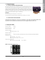
DZSFT outlet probe response curve
Resistance in kOhms
Temperature in °C
The manual control (mains power supply off) can only be activated when the valve is in
the upper position. Valve channel A can be opened manually by applying firm pressure
on the lever from the top towards the middle, and then by pressing it inwards. In this
position, channels A and B are open. This manual position (50 %) can be used to fill
or bleed the pipe network. The valve can be closed again by gently withdrawing the
lever until it is completely released. The valve and the motor will return to their initial
position when the mains power supply is re-established.
The valve opening and closing time is 120 seconds.
It is not necessary to remove the brass valve body when installing a new motor.
Configuring the parameters for a dual zone installation on the indoor unit regulator. Refer to the
instructions in the installation and maintenance manual supplied with the indoor unit.
4.1. FILLING / BLEEDING THE INSTALLATION
4.2. INSTALLATION CONFIGURATION
5. TECHNICAL DATA

12


As part of our ongoing product improvement programme, our products
are subject to change without prior notice. Non contractual photos.
Dans un souci d’amélioration constante, nos produits peuvent être
modifiés sans préavis. Photos non contractuelles.
In dem Bemühen um ständige Verbesserung können unsere Erzeugnisse
ohne vorherige Ankündigung geändert werden. Fotos nicht vertraglich
bindend.
A causa della politica di continua miglioria posta in atto dal costruttore,
questi prodotti sono soggetti a modifiche senza alcun obbligo di preavviso.
Le foto pubblicate non danno luogo ad alcun vincolo contrattuale.
Con objeto de mejorar constantemente, nuestros productos pueden
ser modificados sin previo aviso. Fotos no contractuales.
AIRWELL IndustrIe France
Route de Verneuil
27570 Tillières-sur-Avre
FRANCE
& : +33 (0)2 32 60 61 00
6 : +33 (0)2 32 32 55 13
-
 1
1
-
 2
2
-
 3
3
-
 4
4
-
 5
5
-
 6
6
-
 7
7
-
 8
8
-
 9
9
-
 10
10
-
 11
11
-
 12
12
-
 13
13
-
 14
14
-
 15
15
-
 16
16


Airwell AquaScop AM AQHAS 05-N-2GB Installation and Maintenance Manual
- Taper
- Installation and Maintenance Manual
dans d''autres langues
- English: Airwell AquaScop AM AQHAS 05-N-2GB
Documents connexes
Autres documents
-
 Kessel SPZ 1000 Manuel utilisateur
-
Bradford White BMGH1600 Manuel utilisateur
-
 Olimpia Splendid Maestro Pro Inverter 12 HP Manuel utilisateur
-
 Olimpia Splendid Sherpa 8M Le manuel du propriétaire
-
Chaffoteaux CHAFFOTX BLINDE 300L STABLE O 570 Le manuel du propriétaire
-
Ariston NUOS Le manuel du propriétaire


