Faber Inca Smart 28 Stainless Steel 240 Le manuel du propriétaire
- Catégorie
- Hottes
- Taper
- Le manuel du propriétaire
Ce manuel convient également à

INSP28SS400
INSP28SS600
INCA SMART
Installation Instructions
Use and Care Information
Instructions d'installation
Utilisez et d'entretien
Instrucciones de instalación
Información de uso y cuidado

2
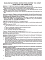
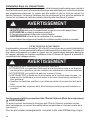
READ AND SAVE THESE INSTRUCTIONS BEFORE YOU START
INSTALLING THIS RANGE HOOD
WARNING: - TO REDUCE THE RISK OF A RANGE TOP GREASE FIRE:
a) Never leave surface units unattended at high settings. Boilovers cause smoking and greasy
spillovers that may ignite. Heat oils slowly on low or medium setting.
b)AlwaysturnhoodONwhencookingathighheatorwhenambeingfood(i.e.Crepes
Suzette, Cherries Jubilee, Peppercorn Beef Flambé).
c) Clean ventilating fans frequently. Grease should not be allowed to accumulate on fan or
lter.
d) Use proper pan size. Always use cookware appropriate for the size of the surface element.
WARNING: - TO REDUCE THE RISK OF INJURY TO PERSONS IN THE EVENT OF A RANGE
TOP GREASE FIRE, OBSERVE THE FOLLOWING*:
a)SMOTHERFLAMESwithaclose-ttinglid,cookiesheet,ormetaltray,thenturnoffthe
burner.BECAREFULTOPREVENTBURNS.Iftheamesdonotgooutimmediately
EVACUATE AND CALL THE FIRE DEPARTMENT.
b) NEVER PICK UP A FLAMING PAN - You may be burned.
c) DO NOT USE WATER, including wet dishcloths or towels - a violent steam explosion will
result.
d) Use an extinguisher ONLY if:
1. You know you have a Class ABC extinguisher, and you already know how to operate
it.
2. Thereissmallandcontainedintheareawhereitstarted.
3. Theredepartmentisbeingcalled.
4. Youcanghttherewithyourbacktoanexit.
* Based on "Kitchen Firesafety Tips" published by NFPA
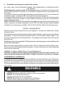
WARNING - TO REDUCE THE RISK OF FIRE OR ELECTRIC SHOCK, do not use this fan with
any solid-state speed control device.
WARNING - TO REDUCE THE RISK OF FIRE, ELECTRICAL SHOCK, OR INJURY TO PERSONS,
OBSERVE THE FOLLOWING:
1. Use this unit only in the manner intended by the manufacturer. If you have any questions,
contact the manufacturer.
2. Before servicing or cleaning unit, switch power off at service panel and lock the service
disconnecting means to prevent power from being switched on accidentally. When the
service disconnecting means cannot be locked, securely fasten a prominent warning
device, such as a tag, to the service panel.
CAUTION: For General Ventilating Use Only. Do Not Use To Exhaust Hazardous or Explosive
Materials and Vapors.
WARNING - TO REDUCE THE RISK OF FIRE, ELECTRICAL SHOCK, OR INJURY TO PERSONS,
OBSERVE THE FOLLOWING:
1. InstallationWorkAndElectricalWiringMustBeDoneByQualiedPerson(s)InAccordance
With All Applicable Codes And Standards, Including Fire-Rated Construction.
2. Sufcientairisneededforpropercombustionandexhaustingofgasesthroughthe
ue(chimney)offuelburningequipmenttopreventbackdrafting.Followtheheating
equipment manufacturer's guideline and safety standards such as those published by
theNationalFireProtectionAssociation(NFPA),andtheAmericanSocietyforHeating,
RefrigerationandAirConditioningEngineers(ASHRAE),andthelocalcodeauthorities.
3. When cutting or drilling into wall or ceiling, do not damage electrical wiring and other
hidden utilities.

3
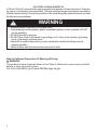
4. Ducted fans must always be vented to the outdoors.
ALL WALL AND FLOOR OPENINGS WHERE THE RANGE HOOD IS INSTALLED MUST
BE SEALED.
This Range Hood requires at least 24" of clearance between the bottom of the Range Hood
and the cooking surface or countertop. This hood has been approved by UL at this distance from
the cooktop.
This minimum clearance may be higher depending on local building codes. For gas cooktops and
combination ranges, a minimum of 30" is recommended and may be required.
Overhead cabinets on both sides of this unit must be a minimum of 18" above the cooking surface
or countertop. Consult the cooktop or range installation instructions given by the manufacturer
before making any cutouts.
MOBILE HOME INSTALLATION The installation of this Range Hood must conform to the Manufactured
Home Construction and Safety Standards, Title 24 CFR, Part 3280 (formerly Federal Standard
for Mobile Home Construction and Safety, Title 24, HUD, Part 280). See Electrical Requirements.
• Venting system MUST terminate outside the home.
• DO NOT terminate the ductwork in an attic or other enclosed space.
• DO NOT use 4" laundry-type wall caps.
• Flexible-type ductwork is not recommended.
• DO NOT obstruct the ow of combustion and ventilation air.
• Failure to follow venting requirements may result in a re.
WARNING
!
VENTING REQUIREMENTS
Determine which venting method is best for your application. Ductwork can extend either through
the wall or the roof.
The length of the ductwork and the number of elbows should be kept to a minimum to provide efcient
performance. The size of the ductwork should be uniform. Do not install two elbows together. Use
duct tape to seal all joints in the ductwork system. Use caulking to seal exterior wall or oor opening
around the cap.
Flexible ductwork is not recommended. Flexible ductwork creates back pressure and air turbulence that
greatly reduces performance.
Make sure there is proper clearance within the wall or oor for exhaust duct before making cutouts.
Do not cut a joist or stud unless absolutely necessary. If a joist or stud must be cut, then a supporting
frame must be constructed.
WARNING - To Reduce The Risk Of Fire, Use Only Metal Ductwork.
CAUTION-Toreduceriskofreandtoproperlyexhaustair,besuretoductairoutside–Do
not vent exhaust air into spaces within walls or ceilings or into attics, crawl spaces, or garages.
Cold Weather installations
An additional back draft damper should be installed to minimize backward cold air ow and a
nonmetallic thermal break should be installed to minimize conduction of outside temperatures
as part of the vent system. The damper should be on the cold air side of the thermal break.
The break should be as close as possible to where the vent system enters the heated portion
of the house.

4
• Electrical ground is required on this Range Hood.
• If cold water pipe is interrupted by plastic, nonmetallic gaskets or other materials, DO NOT
use for grounding.
• DO NOT ground to a gas pipe.
• DO NOT have a fuse in the neutral or grounding circuit. A fuse in the neutral or grounding
circuit could result in electrical shock.
• Check with a qualied electrician if you are in doubt as to whether the Range Hood is
properly grounded.
• Failure to follow electrical requirements may result in a re.
WARNING
!
StateofCaliforniaProposition65Warning(USonly)
WARNING
This product contains chemicals known to the State of California to cause cancer and birth
defects or other reproductive harm.
For more information go to www.P65Warnings.ca.gov
ELECTRICAL REQUIREMENTS
A 120 volt, 60 Hz AC-only electrical supply is required on a separate 15 amp fused circuit. A time-de-
lay fuse or circuit breaker is recommended. The fuse must be sized per local codes in accordance
with the electrical rating of this unit as specied on the serial/rating plate located inside the unit near
the eld wiring compartment.

5
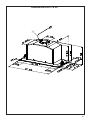
RANGE HOOD DIMENSIONS 28"
47 "

6
MIN. 24" OVER ELECTRIC
INSTALLATION HEIGHT REQUIREMENTS
MIN. 30" OVER GAS

7
12a Pozi Screws (1/8" x 5/8")
10
12b Pozi Screws (1/8" x 1/2")
4
12e Torx Screws (1/8" x 3/8")
2
Torx Screwdriver
Pozi Screwdriver
H
I
H
I
H
I
12b
12e
8
12a
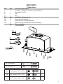
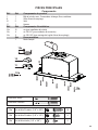
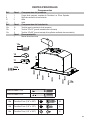
MAIN PARTS
Components
Ref. Qty. Product Components
1 1 Hood Body, complete with: Controls, Light, Filters,Blower.
8 1 Recirculation Vent Grill
10 2 Flap
11 1 Ring
Ref. Qty. Installation Components
12a 10 Screws (for hood installation)
12b 4 Screws 1/8"x1/2" (for Cover installation)
12e 2 Screws 1/8"x3/8" (for Recirculation Vent Grill mounting)
Qty. Documentation
1 Instruction Manual
H
I
10
H
I
11

8
Available Accessories
Parts needed
- 6" Round Metal ductwork .
Direct Connect Wiring Box sku # WIREBOX
Liner 30" Stainless #LINE30ST
Liner 36" Stainless #LINE36ST
Activated Charcoal Filter sku #; FILTER1
Activated Charcoal Filter sku #; FILTER1LL
Created by
-
Denomination
-
Lang EN
Sheet
1
/1
Modif.by
Approved by
Approval date
Doc. status
Drawing N.
NEW_DRAWING_BOX
Rev
01
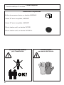
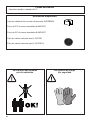
Two men required for installation Wear work gloves for safety

9
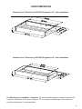
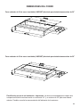
LINER DIMENSIONS
Version 09/14 - Page 4
SIDE VIEW / LA PERSPECTIVE DE CÔTÉ
FRONT VIEW / LA PERSPECTIVE DE FRONT
BOTTOM VIEW / LA PERSPECTIVE DE BAS
Standard Liner 36 Stainless (LINE36ST)
designed for 36” wide installations
Cadre Standard 36 Axier Inoxydable (LINE36ST)
peut être employée les hottes encastrable sur mesure de 36"
Standard Liner 30 Stainless (LINE30ST)
designed for 30” wide installations
Cadre Standard 30 Axier Inoxydable (LINE30ST)
peut être employée les hottes encastrable sur mesure de 30"
Note: Standard Liners are pre-cut for installation of Inca Smart. For installations with the Inca HC SS, remove the additional perforated section.
Note: Les Cadres Standard sont précoupés pour l'installation de l'Inca Smart. Pour des installations avec L'Inca HC SS, enlevez la section perforée
additionnelle.
RANGEHOOD DIMENSIONS / DIMENSIONS DE LA HOTTE
LINER DIMENSIONS / DIMENSIONS DU CADRE
Pre-Planning Your Installation -
Important: The recommended height to install this hood off the cooktop is
a minimum of 24" and a maximum of 30” for maximum effectiveness. Also consult the cooktop manufacturer’s
recommendation.
Planiez votre installation - Important : La hauteur recommandée pour installer cette hotte au-dessus de la
surface de cuisson est d’un minimum de 24” et d’un maximum de 30” pour un maximum d’efcacité. De plus,
nous vous recommandons consulter le manuel de recommandations du fabricant de la surface de cuisson.
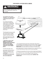
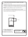
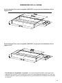
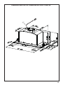
NOTE: Remove the metal packaging support
piece from the top of the hood before
installation (SEE RIGHT)
NOTE : Enlevez le morceau de empaquetage de
soutien en métal du dessus du hotte avant
installation (VOYEZ BIEN)
Version 09/14 - Page 4
SIDE VIEW / LA PERSPECTIVE DE CÔTÉ
FRONT VIEW / LA PERSPECTIVE DE FRONT
BOTTOM VIEW / LA PERSPECTIVE DE BAS
Standard Liner 36 Stainless (LINE36ST)
designed for 36” wide installations
Cadre Standard 36 Axier Inoxydable (LINE36ST)
peut être employée les hottes encastrable sur mesure de 36"
Standard Liner 30 Stainless (LINE30ST)
designed for 30” wide installations
Cadre Standard 30 Axier Inoxydable (LINE30ST)
peut être employée les hottes encastrable sur mesure de 30"
Note: Standard Liners are pre-cut for installation of Inca Smart. For installations with the Inca HC SS, remove the additional perforated section.
Note: Les Cadres Standard sont précoupés pour l'installation de l'Inca Smart. Pour des installations avec L'Inca HC SS, enlevez la section perforée
additionnelle.
RANGEHOOD DIMENSIONS / DIMENSIONS DE LA HOTTE
LINER DIMENSIONS / DIMENSIONS DU CADRE
Pre-Planning Your Installation -
Important: The recommended height to install this hood off the cooktop is
a minimum of 24" and a maximum of 30” for maximum effectiveness. Also consult the cooktop manufacturer’s
recommendation.
Planiez votre installation - Important : La hauteur recommandée pour installer cette hotte au-dessus de la
surface de cuisson est d’un minimum de 24” et d’un maximum de 30” pour un maximum d’efcacité. De plus,
nous vous recommandons consulter le manuel de recommandations du fabricant de la surface de cuisson.
NOTE: Remove the metal packaging support
piece from the top of the hood before
installation (SEE RIGHT)
NOTE : Enlevez le morceau de empaquetage de
soutien en métal du dessus du hotte avant
installation (VOYEZ BIEN)
Pre-Planning your Installation - Important: The recommended height to install this hood off the
cooktop is a minimum of 24" and a maximum 30" for maximum effectiveness. Also consult the
cooktop manufacturer's recommendation.
StandardLiner30Stainless(LINE30ST)designedfor30”wideinstallations
StandardLiner36Stainless(LINE36ST)designedfor36”wideinstallations

10
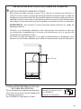
FOR INSTALLATION WITH LINERS
When building a custom hood, always
follow all applicable codes and
standards.
WARNING
!
The Inca Smart can be used in
standard 30" or 36" wide cabinetry
or with custom hoods 30" wide
and up.
For custom/wood hoods,
choose either YOUR OWN
custom liner or our Standard
Liner designed for 30" and
36" wide installations. Liners
create a perfectly - sealed,
non-combustible nish for the
underside of your custom/
wood hood.
The Standard Liners are made
up of two sections: a larger,
rear section (pre-cut out for
insertion of the Inca Smart)
and a front section for a total
adjustable depth between 16"
and 17 7/8".
!!! IMPORTANT NOTE: DO NOT
REMOVE THE ADDITIONAL
PERFORATED SECTION AROUND
THE PRE-CUT-OUT WHEN
INSTALLING THE STANDARD
LINER WITH THE INCA SMART
MODEL.
Consider the shape, size,
and weight of the Inca Smart
and Liner to determine the
conguration of the custom/
wood hood.
See RANGEHOOD DIMENSIONS
AND LINER DIMENSIONS.
1. The custom/wood hood must have a sturdy base (3/4" plywood
recommended) to accomodate the cut-out for the Inca Smart. The base
must be recessed to accomodate the height of the Liner (see LINER
DIMENSIONS). The Liner attaches to the bottom of the base using
screws appropriate for the size and material of your custom/wood hood.
The Inca Smart inserts into the cut-out in the Liner and base.
2. Position the rear section of the Liner so that it abuts the back edge of
your custom/wood hood. Using a pen, trace the outline of the pre-cut out.
Remove the Liner and proceed to MAKE YOUR CUT-OUTS.
Install both sections of the Liner and proceed to INSTALL THE
RANGEHOOD.
Version 09/14 - Page 5
The Inca Smart requires 5" round ductwork. To ensure that the blower performs to its
highest possible capacity, ductwork should be as short and straight as possilbe.
Make your ductrun as straight and short as possible. The ductrun should not exceed 25
equivalent feet if ducted with the required minimum of 5" round duct. Count 45º angles
as 3 feet, 90º elbows as 5 feet, and 90º at elbows as 12 feet.
For best results, use no more than three 90° elbows. Make sure that there is a minimum
of 24" of straight duct between elbows if more than one is used. Do not install two
elbows together. If you must elbow right away, do it as far away from the hood's
exhaust opening as possible.
TOOLS NEEDED FOR INSTALLATION
• Saber Saw or Jig Saw
• Drill
• 1 1/4" Wood Drill Bit
• Pliers
• Phillips Screwdriver
• Wire Stripper or Utility Knife
• Metal Snips
• Measuring Tape or Ruler
• Level
• Pencil
• Caulking Gun
• Duct Tape
PLAN YOUR DUCTWORK
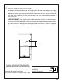
The Inca Smart can be used in
standard 30" or 36" wide cabinetry
or with custom hoods 30" wide
and up.
For custom/wood hoods, choose
either YOUR OWN custom liner or
our Standard Liner designed for 30"
and 36" wide installations. Liners
create a perfectly-sealed, non-
combustible nish for the underside
of your custom/wood hood.
The Standard Liners are made
up of two sections: a larger, rear
section (pre-cut out for insertion of
the Inca Smart) and a front section
for a total adjustable depth between
16" and 17
7/8".
!!! IMPORTANT NOTE: DO NOT
REMOVE THE ADDITIONAL
PERFORATED SECTION
AROUND THE PRE-CUT-
OUT WHEN INSTALLING
THE STANDARD LINER WITH
THE INCA SMART MODEL.
THIS PERFORATION IS ONLY
REMOVED FOR USE WITH THE
INCA HC SS MODEL.
Consider the shape, size, and
weight of the Inca Smart and Liner
to determine the configuration
of the custom/wood hood. See
RANGEHOOD DIMENSIONS AND
LINER DIMENSIONS on Page 4.
FOR INSTALLATIONS WITH LINERS
PARTS SUPPLIED FOR INSTALLATION
• 1 Backdraft Damper
• 10 Screws
• Field Wiring Box
• 1 Literature Package
PARTS NEEDED FOR INSTALLATION
• 2 Conduit Connectors
• Power Supply Cable
• Scews for Field Wiring Box
• 1 Wall or Roof Cap
• All Metal Ductwork
OPTIONAL ACCESSORIES AVAILABLE
• Charcoal Filter Kit
For recirculating installations only,
replace charcoal lters as needed
part # FILTER4
• Liners
Create a perfectly-sealed, non-combustible
perimeter around the Inca Smart. Depth adjustable
from 16" - 17
7/8"
.
Standard Liner 30 Stainless - part #
LINE30ST
Standard Liner 36 Stainless - part # LINE36ST
CUSTOM/WOOD
HOOD
STANDARD LINER
INCA SMART
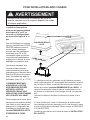
WARNING
!
When building a custom hood,
always follow all applicable
codes and standards.
1. The custom/wood hood must have a sturdy base (3/4" plywood recommended) to accomodate
the cut-out for the Inca Smart. The base must be recessed to accomodate the height of the
Liner (see LINER DIMENSIONS on Page 4). The Liner attaches to the bottom of the base
using screws appropriate for the size and material of your custom/wood hood. The Inca Smart
inserts into the cut-out in the Liner and base.
2. Position the rear section of the Liner so that it abuts the back edge of your custom/wood
hood. Using a pen, trace the outline of the pre-cut out. Remove the Liner and proceed to MAKE
YOUR CUT-OUTS on Page 6. Install both sections of the Liner and proceed to INSTALL THE
RANGEHOOD on Page 6.
CUSTOM/WOODH
HOOD
STANDARD LINER
INCA SMART

11
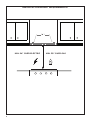
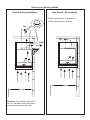
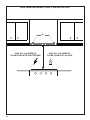
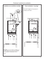
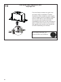
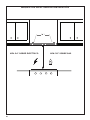
Choose your ducting method
Rear
Top
6"
Non Ducted - RecirculationDucted Venting Installation
Requires purchase of Activated
Charcoal Accessory #Filter1
Caution: If an elbow is required,
do it as far away from the hood's
exhaust opening as possible.

12
1
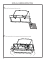
Remove grease lters and set aside.
INSTALL THE RANGE HOOD
2
Remove the bottom of the Range Hood by pulling as shown.

13
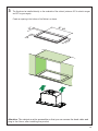
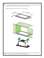
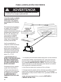
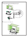
3
The Hood can be installed directly on the underside of the cabinet (minimum 24" for electric ranges
and 30" for gas ranges).
Create an opening in the bottom of the Cabinet, as shown.
10 1/2”
1/2”
26” 5/8
10 1/2”
1/2”
26” 5/8
1/2”
10 1/4”
26” 5/8
1/2”
Attention: The cabinet must be accessible so that you can access the hood cable and
plug in the future, after installing the product

14
10 1/2”
1/2”
26” 5/8
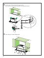
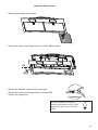
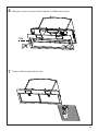
Min.9/16"
Max 1" 3/16
Vf
Insert the hood until the side supports snap into place.
Lock in position by tightening the screws Vf from underneath the hood.
4
Fasten using the 10 screws 12a provided.
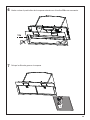
5

15
Replace the bottom of the Range Hood by 4 screws 12b as shown.
Place the grease lters in the hood
6
7
12b

16
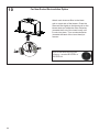
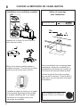
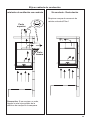
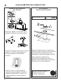
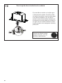
Ducted Venting Installation
8
Non Ducted -
Recirculation Option
Install the 2 Flap 10 included with the
Range Hood as shown.
Break the 4 pre-cutting pieces and install
the Ring 11 included with the Range
Hood before connecting to the ductwork.
Install Roof or Wall Cap purchased
separately. Connect the 6" metal duct-
work to the Roof or Wall Cap and then
attach ductwork.
´
For Non-Ducted Recirculation venting route
the ductwork to a location above the hood
where the discharge is vented back into the
room.
Use the included Recirculation Vent Grill to
cover the opening. Secure the grill with the
2 screws provided in the Install Kit.
Required Activated Charcoal
Filter Accessory - sku #FILTER1
or #FILTER1LL
CHOOSE YOUR DUCTING METHOD
12e
8
Torx Screwdriver
10
11

17
Direct Connect Wiring Box
Accessory sku # WIREBOX
(purchased separately)
Created by
-
Denomination
-
Lang EN
Sheet
1
/1
Modif.by
Approved by
Approval date
Doc. status
Drawing N.
NEW_DRAWING_BOX
Rev
01
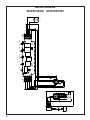
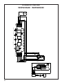
ELECTRICAL INSTALLATION WITH
OPTIONAL WIRING BOX
For Permanent wiring Installation-Use only
with Listed Range Hood Wiring Box kit
sku # WIREBOX, manufactured by Faber.
Max. 33 7/16”
9
ELECTRICAL INSTALLATION WITH CONNECTION CABLE
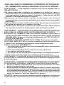
GROUNDING INSTRUCTIONS
This appliance must be grounded. In the event of an electrical short circuit, grounding
reduces the risk of electric shock by providing an escape wire for the electric current.
This appliance is equipped with a cord having a grounding wire with a grounding
plug. The plug must be plugged into an outlet that is properly installed and grounded.
WARNING - Improper grounding can result in a risk of electric shock.
Consult a qualied electrician if the grounding instructions are not completely under-
stood, or if doubt exists as to whether the appliance is properly grounded.
Do not use an extension cord. If the power supply cord is too short, have a qualied
electrician install an outlet near the appliance.

18
1
2
10
For Non-Ducted Recirculation Option
Attach each charcoal lter to the black
grid on each side of the blower. Press the
charcoal lter tightly to the black grid on the
blower side and rotate the lter clockwise
(towards the front of the insert hood) until
it locks into place. Turn counterclockwise
(towards the back of the insert hood) to
remove.
Required Activated Charcoal Filter
Accessory - sku sku #FILTER1 or
#FILTER1LL

19
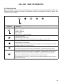
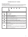
USE AND CARE INFORMATION
For Best Results
Start the Range Hood several minutes before cooking to develop proper airow. Allow the
Range Hood to operate for several minutes after cooking is complete to clear all smoke and
odors from the kitchen.
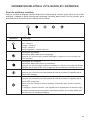
Button Function
LED indicator light (L) - indicates current speed with color
Green - speed 1
Orange - speed 2
Red - speed 3
Flashing Red - intensive speed
Light On/Off Button
On/Off switch for the lights.
Press the button to turn the light ON and press again to turn it OFF.
Blower On/Off Button
On/Off button for the blower.
Press the button to turn the blower ON to speed one (indicated by green LED)
and press again to turn the hood off.
Blower Speed 2
Press this button to turn the hood onto speed #2. (indicated by orange LED).
Blower Speed 3 / Intensive
Press this button to turn the hood onto speed #3. (indicated by solid red LED)
Hold down the speed 3 button for 2 seconds to activate the intensive speed.
The intensive speed setting is indicated by a blinking red light.
This operates the hood for 10 minutes on the highest speed and then returns to
the previous speed.

20
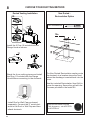
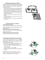
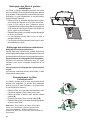
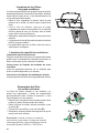
Cleaningmetalgreaselters
The metal grease lters can be cleaned in hot detergent
solution or washed in the dishwasher. They should be
cleaned every 2 months use, or more frequently if use
is particularly heavy.
• Remove the lter, pushing the lever towards the back
of the unit and at the same time pulling downward.
• Wash the lter without bending it, leave it to dry
thoroughly before replacing (if the surface of the lter
changes color over time, this will have absolutely no
effect on its efciency).
• Replace, taking care to ensure that the handle faces
forward.
• Cleaning in dishwasher may dull the nish of the
metal grease lter.
• No water can be present in lters before installing
back in hood.
Cleaning Exterior surfaces
Cleaning Exterior surfaces:
Please note, abrasives and scouring agents can scratch
range hood nishes and should not be used to clean
nished surfaces.
Stainless Steel nish cleaning instructions:
Clean exterior surfaces with a commercially available
stainless steel cleaner.
Painted Gray nish cleaning instructions:
Clean exterior surfaces with hot soapy water.
Replacing Activated Charcoal Filter
The Activated Charcoal Filters are not washable
and cannot be regenerated, and must be replaced
approximately every 4 months of operation, or more
frequently with heavy usage.
• Remove the Filter, pushing it towards the back of the
unit and at the same time pulling downward.
• Remove the saturated Activated Charcoal Filters,
as indicated (A).
• Fit the new Filters, as indicated (B).
• Replace, taking care to ensure that the handle faces
forwards.
Caution: When used in recirculation mode, to
Reduce the Risk of Fire and Shock use only con-
version kit Model FILTER1 or FILTER1LL.
La page est en cours de chargement...
La page est en cours de chargement...
La page est en cours de chargement...
La page est en cours de chargement...
La page est en cours de chargement...
La page est en cours de chargement...
La page est en cours de chargement...
La page est en cours de chargement...
La page est en cours de chargement...
La page est en cours de chargement...
La page est en cours de chargement...
La page est en cours de chargement...
La page est en cours de chargement...
La page est en cours de chargement...
La page est en cours de chargement...
La page est en cours de chargement...
La page est en cours de chargement...
La page est en cours de chargement...
La page est en cours de chargement...
La page est en cours de chargement...
La page est en cours de chargement...
La page est en cours de chargement...
La page est en cours de chargement...
La page est en cours de chargement...
La page est en cours de chargement...
La page est en cours de chargement...
La page est en cours de chargement...
La page est en cours de chargement...
La page est en cours de chargement...
La page est en cours de chargement...
La page est en cours de chargement...
La page est en cours de chargement...
La page est en cours de chargement...
La page est en cours de chargement...
La page est en cours de chargement...
La page est en cours de chargement...
La page est en cours de chargement...
La page est en cours de chargement...
La page est en cours de chargement...
La page est en cours de chargement...
La page est en cours de chargement...
La page est en cours de chargement...
La page est en cours de chargement...
La page est en cours de chargement...
La page est en cours de chargement...
La page est en cours de chargement...
La page est en cours de chargement...
La page est en cours de chargement...
-
 1
1
-
 2
2
-
 3
3
-
 4
4
-
 5
5
-
 6
6
-
 7
7
-
 8
8
-
 9
9
-
 10
10
-
 11
11
-
 12
12
-
 13
13
-
 14
14
-
 15
15
-
 16
16
-
 17
17
-
 18
18
-
 19
19
-
 20
20
-
 21
21
-
 22
22
-
 23
23
-
 24
24
-
 25
25
-
 26
26
-
 27
27
-
 28
28
-
 29
29
-
 30
30
-
 31
31
-
 32
32
-
 33
33
-
 34
34
-
 35
35
-
 36
36
-
 37
37
-
 38
38
-
 39
39
-
 40
40
-
 41
41
-
 42
42
-
 43
43
-
 44
44
-
 45
45
-
 46
46
-
 47
47
-
 48
48
-
 49
49
-
 50
50
-
 51
51
-
 52
52
-
 53
53
-
 54
54
-
 55
55
-
 56
56
-
 57
57
-
 58
58
-
 59
59
-
 60
60
-
 61
61
-
 62
62
-
 63
63
-
 64
64
-
 65
65
-
 66
66
-
 67
67
-
 68
68


Faber Inca Smart 28 Stainless Steel 240 Le manuel du propriétaire
- Catégorie
- Hottes
- Taper
- Le manuel du propriétaire
- Ce manuel convient également à
dans d''autres langues
Documents connexes
-
Faber INSD29SSV Guide d'installation
-
-
-
-
-
-
-
-
-
