GE GDF520PSJ0SS Guide d'installation
- Catégorie
- Lave-vaisselle
- Taper
- Guide d'installation
Ce manuel convient également à

Installation
Built-In Dishwasher
Instructions
Ifyou have questions, call 800.GE.CARES(800.432.2737)or visit our Website at: GEAppliances.com.
InCanada, please call i.800.S6E.3344 or visit www.geappliances.ca
BEFOREYOU BEGIN
Readthese instructions completely and carefully.
A WARNING:
To reduce the risk of electric shock, fire, or injury to
persons, the installer must ensure that the dishwasher is
completely enclosed at the time of installation.
FORPERSONALSAFETY:Remove house fuse or open
circuit breaker before beginning installation. Do not use an
extension cord or adapter plug with this appliance.
The improper connection of the equipment grounding
conductor can result in a risk of electric shock. Check with
a qualified electrician or service representative if you are
in doubt that the appliance is properly grounded.
If house wiring isnot 2-wire with ground, a ground
must be provided by the installer. When house wiring
isaluminum, be sure to use UL-Listed anti-oxidant
compound and aluminum-to-copper connectors.
A CAUTION: oonotremovewoodbaseunt_,
you are ready to install the dishwasher. The dishwasher will
tip over when the door is opened if base isremoved.
A ADVERTENCIA:
Para reducir el riesgo de descarga el6ctrica, incendio o
lesiones a personas, el instalador debe asegurarse de que
el lavaplatos est6 completamente cerrado en el momento
de la instalaci6n.
PARASEGURIDADPERSONAL:Ouite el fusible o abra el
interruptor de circuitos antes de comenzar la instalaci6n.
No utilice un cable de extensi6n o un enchufe adaptador
con este artefacto.
La conexi6n inadecuada del conductor de conexi6n a
tierra del equipamiento puede provocar un riesgo de
descarga el6ctrica. Consulte a un electricista calificado o
representante de servicio t6cnico si tiene dudas sabre la
correcta conexi6n a tierra del aparato.
Siel cableado dom6stico no cuenta con un cable de 2
hilos con conexi6n a tierra, un instalador debe realizar una
conexi6n a tierra. Cuando el cableado dom6stico es de
aluminio, aseg0rese de usar un compuesto antioxidante y
conectores de aluminio a cobre aprobados par UL.
A °
PRECAUCION: No quite la base de
madera hasta que est@listo para instalar el lavaplatos. Sise
quita la base,el lavaplatos sevolcarc_cuando seabra la puerta.
FOR YOUR SAFETY
Read and observe all WARNINGSand CAUTIONSshown
throughout these instructions. While performing installations
described in this booklet, gloves, safety glasses or goggles
should be worn.
IMPORTANT - Observeallgoverning codesand
ordinances.
Note to Installer - Be sure to leave these instructions for the
consumer's and local inspector's use.
, Note to Consumer - Keepthese instructions with your
Owner's Manual for future reference.
Skill Level - Installation of this dishwasher requires
basic mechanical, electrical and plumbing skills. Proper
installation is the responsibility of the installer. Product
failure due to improper installation is not covered under
the GEAppliance Warranty. See warranty information.
Completion Time - :1to 3 Hours. New installations require
more time than replacement installations.
IMPORTANT - ThedishwasherMUSTbeinstalledto
allow for future removal from the enclosure if service is required.
Careshouldbeexercisedwhenthe applianceisinstalledor removed,
to reduce the likelihood of damage to the power supply cord.
If you received a damaged dishwasher, you should immediately
contact your dealer or builder.
Optional Accessories - Seethe Owner's Manual for available
custom panel kits.
READ CAREFULLY.
KEEP THESE INSTRUCTIONS.
//
/
/
i,, / //
/
Printed in the United States 31-31545 09-14 GE

Installation Preparation
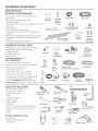
PARTS SUPPLIED
IN INSTALLATION PACKAGE:
. Junction box cover and #10 hex-head screw
. Hose clamp
. Drain hose (approximately 78" long)
. Drain hose hanger
.2 #8-18 hex head screws to secure brackets to washer
tub frame
.2 Plug buttons
.2 side trim pieces (some models)
.2 mounting brackets for wood countertops or side
cabinets
.2 #8-18 x 5/8" Phillips special head screws, to secure
dishwasher to underside of countertop or to side
cabinets
Literature, samples and/or coupons
Junction
Box Cover
?
#10
Hex-Head
Junction
BoxScrew
112" long
Drain Hose Hanger
Hose Clamp
??
#8 Hex-Head Mounting
Bracket Screws
(onsome models)
Mounting
Brackets
Drain Hose
n
Plug Buttons
#8 Phillips
Special
Head Screws
5/8" long
MATERIALS YOU WILL NEED:
.90 ° elbow PA" hose internal thread on one end,
opposite end sized to fit water supply)
. Thread seal tape
. UL-listed wire nuts (3)
. Masking Tape
Materials Needed for
New Installations:
. Air gap for drain hose, if required
. Waste tee for house plumbing, if applicable
. Electrical cable or power cord
. Screw-type hose clamps
. Strain relief for electrical connection
. Hand shut-off valve (recommended)
. Hot water line-3/8" minimum, copper tubing
(including ferrule, compression nut) or
GE Part # W×28×326, flexible braided hose
. WD24×10065 drain hose (12' long), if needed
90° Elbow
Thread
Seal Tape
(if applicable)
?
Waste Tee
Air Gap
Hand
Shut-Off
Valve
HoseClamps
Wire Nuts (3)
Electrical Cable
forPower Cord, if applicable)
Q
Strain Relief
Masking Tape
(if applicable)
Hot Water Line
Optional
12' Drain Hose
Coupler for
optional drain
hose
TOOLS YOU WILL NEED: _.
. Phillips-head screwdriver
. 1/4" and 5/16" nutdriver
. 6" Adjustable wrench Phill
Screwdriver
Level
. Carpenter's square
. Measuring tape
. Safety glasses
. Flashlight 15/16" Socket
Bucket to catch water when flushing the line
. 15/16" socket (optional for skid removal)
Gloves L-________VJ
. Pliers Flashlight
Nutdriver
Pliers
Adjustable
Wrench
Level
Tubing Cutter
Carpenter's
Square
Safety Glasses
For.ew,n tollo ion Only:
. Tubing cutter
. Drill and appropriate bits
Hole saw set
Bucket Gloves Hole SawSet
Measuring Tape

Installation Preparation
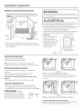
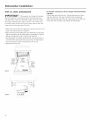
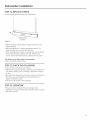
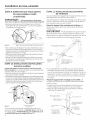
PREPARE DISHWASHER ENCLOSURE
AWARNING:
Toreducethe riskofelectricshock,fire,or injuryto persons,the
installermustensurethat the dishwasheriscompletelyenclosedat
thetime of installation.
35-1/2" to 5/4-5/4"
Underside of
Countertop
to Floor
Figure A
ThisWallArea
mustbe Free
of Pipesor
wires
£abinets
Square
and
Plumb
* The rough cabinet opening must be at least 2/4"deep, 2/4"
wide and approximately 34-1/2" high from floor to underside
of the countertop.
A ADVERTENCIA:
Parareducirelriesgode descargael@ctrica,incendioo lesionesa
personas,el instaladordebeasegurarsedeque el lavaplatosest@
completamentecerradoen el momentadela instalaci6n.
* The dishwasher must be installed so that drain hose is no
more than 12' in length for proper drainage.
* The dishwasher must be fully enclosed on the top, sides and
back, and must not support any part of the enclosure.
CLEARANCES: /
• Wheninstalledintoa corner, Countertop
allow 2"rain.clearance
betweendishwasherand
adjacentcabinet,wallorother
appliances.Allow28-5/8"rain.
clearancefrom thefront
of thedishwasherfor door
opening.FigureB.
Figure B
Clearancefor Door
Opening 2" Minimum
DRAIN REQUIREMENTS
, Follow local codes and ordinances.
, Do not exceed 12' distance to drain.
NOTE:Air gap must be used, if waste tee or disposer
connection is less than 18" above floor to prevent siphoning.
DETERMINE DRAIN METHOD
The type of drain installation depends on the following
questions.
. Do local codes or ordinances require an air gap?
. Iswaste tee less than 18"above floor?
If the answer to either question isYES,Method 1 MUST
be used.
. If the answers are NO,either method may be used.
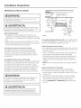
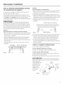
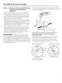
CABINET PREPARATION
, Drill a 1-1/2" diameter hole in the cabinet wall within
the shaded areas shown in Figure A for the drain hose
connection. The hole should be smooth with no sharp edges.
IMPORTANT -When
connectingdrainlinetodisposer,
checktobesurethatdrainplughas
beenremoved.DISHWASHER WILL
NOT DRAIN IFPLUG ISLEFTINPLACE.
4 Remove
Drain
Plug
Figure C
Method 1 - Air Gap with Waste Tee or Disposer
Anair gap mustbe usedwhen requiredbylocalcodesand ordi-
nances.Theair gap must beinstalledaccordingto manufacturer's
instructions.
DrainHoseHanger
Figure D
_Hanger
L
L
Method 2 - "High Drain Loop" with Waste Tee or Disposer
\
Tip: Avoid unnecessary service call charges.
Always be sure disposer drain plug has been removed before
attaching dishwasher drain hose to the disposer.

Installation Preparation
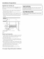
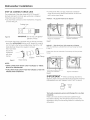
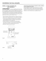
PREPARE ELECTRICAL WIRING
WARNING:
FORPERSONALSAFETY:Removehousefuseor opencircuit breaker
beforebeginninginstallation.Donot usean extensioncordor
adapter plugwith this appliance.
],
Receptacle \
. I \
Location in Adjacent _ ,,
%
ADVERTENCIA:
PARASEGURIDADPERSONAL:Quiteelfusibleo abra el interruptor
de circuitosantesde comenzarla instalaci6n.Noutiliceuncable
de extensi6no unenchufeadaptador conesteartefacto.
Electrical Requirements
, This appliance must be supplied with !20V, 60 Hz.,and
connected to an individual properly grounded branch circuit,
protected by a 15- or 20-ampere circuit breaker or time-delay
fuse.
, Wiring must be 2 wire with ground and rated for 75°C(176%).
, If the electrical supply does not meet the above requirements,
call a licensed electrician before proceeding.
Grounding Instructions-Permanent Connection
This appliance must be connected to a grounded metal,
permanent wiring system, or an equipment-grounding
conductor must be run with the circuit conductors and be
connected to the equipment-grounding terminal or lead on
the appliance.
Grounding Instructions-Power Cord Models
This appliance must be grounded. In the event of a malfunction
or breakdown, grounding will reduce the risk of electric shock
by providing a path of least resistance for electric current.
This appliance is equipped with a cord having an equipment-
grounding conductor and a grounding plug. The plug must
be plugged into an appropriate outlet that is installed and
grounded inaccordance with all local codes and ordinances.
AWARNING:
Theimproperconnectionof theequipmentgrounding conductor
can resultin a riskofelectricshock.Checkwith a qualified
electricianor servicerepresentativeifyou are indoubt that
the applianceisproperlygrounded.
Cabinet
Figure E White
For models equipped with power cord: Do not modify the plug
provided with the appliance; if it will not fit the outlet, have a
proper outlet installed by a qualified technician.
Cabinet Preparation & Wire Routing
, Thewiring may enter the opening from either side, rear or the
floor within the shaded area illustrated above in Figure Eand
defined in Figure A.
, Cut a 1-1/2" maximum diameter hole to admit the electrical
cable. Edgesof hole should be smooth and rounded.
Permanent wiring connections may pass through the same
hole as the drain hose and hot water line, if convenient. If
cabinet wall is metal, the hole edge must be covered with a
bushing.
NOTE:Power cords with plug must pass through a separate
hole.
Electrical Connection to Dishwasher
Electrical connection is on the right front of dishwasher.
, For permanent connections the cable must be routed as
shown in Figure E.Cable must extend a minimum of 24" from
the rear wall.
, For power cord connections, install a 3-prong grounding
type receptacle in the sink cabinet rear wall, 6" min. or 18"
maximum from the opening, 6" to 18" above the floor.
, Useonly W×09×70910 or W×09×70911 Dishwasher Power
Cord Kit.
A ADVERTENCIA:
Laconexi6ninadecuadadelconductordeconexi6natierradel
equipamientopuedeprovocarunriesgodedescargael_ctrica.
Consultea unelectricistacalificadoorepresentantedeservicio
t_cnicositienedudassabrelacorrectaconexi6natierradelaparato.

Installation Preparation
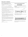
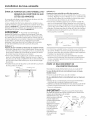
PREPARE HOT WATER LINE
NOTE:GErecommends copper tubing for the water line, but if
you choose to useflexible hose, use GE'sW×28×326, flexible
braided hose.
. Thewater supply line (3/8" copper tubing or flexible braided
hose) may enter from either side, rear or floor within the
shaded area shown in Figure F.
. Thewater supply line may pass through the same hole as the
electrical cable and drain hose. Or,cut an additional 1-1/2"
diameter hole to accommodate the water line. If power cord
with plug is used, water line must not pass through power
cord hole.
ACAUTION:
Do not remove wood base until you are ready to install the
dishwasher. The dishwasher will tip over when the door is
opened if base isremoved.
PRECAUCION:
Noquite la base de madera hasta que est_ listo para instalar el
lavaplatos. Sisequita la base, el lavaplatos sevolcar6 cuando
se abra la puerta.
il Shut-off_
Hot
From
Cabinet
Cabinet
FigureF
2" From Floor
Water Line Connection
. If using a flexible braided supply hose, labelthe hose with the
installation date to use as reference. Flexible braided hoses,
elbows and gaskets should be replaced in 5years.
. Turn off the water supply.
. Install a hand shut-off valve in an accessible location, such
as under the sink. (Optional, but strongly recommended and
may be required by local codes.)
. Water connection is on the left side of the dishwasher. Install
the hot water inlet line, using no less than 3/8" copper tubing
or a flexible braided hose. Route the line as shown in Figure F
and extend forward at least 19"from rear wall.
. Adjust water heater for 120°F to 140°Ftemperature.
. Flush water line to clean out debris.
. The hot water supply line pressure must be 20-120 PSI.
Turn page to begin dishwasher installation,

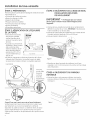
Dishwasher Installation
STEP 1:PREPARATION
Locate the items in the installation package:
, Screws
, Junction box cover
, Drain hose and clamp
, Mounting brackets
, Trim pieces (onsome models)
, Drain hose hanger
, Owner's Manual
, Product samples and/or coupons
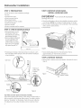
STEP 2: CHECK DOOR BALANCE
, With dishwasher on the
wood base, check the
door balance by opening
and closing the door.
, Door isproperly balanced
if, when opened, it self
closes within 20°from
vertical, stays in position
from 20°to 70° and falls
fully open beyond 70°.
/
Door _
closes /
within /
20 ° /
/
/ Door stays in
Position from _- _
20°to 70_ . -- -- "_
_Door falls fully __
open beyond 70°_
, Ifnecessary increase or decrease tension as shown. Latch
door and adjust both springs to the same tension setting to
correct balance.
Side View
Make sure
pulley cable
iswithin
pulley
shoulders
Increase
Tension
]
Front View
Decreas_
Tension
Figure G
STEP 3: REMOVE WOOD BASE,
INSTALL LEVELING LEGS
IMPORTANT - Do not kickoffwood base!
Damage will occur.
, Move the dishwasher close to the installation location and lay
it on its back. NOTE:Do not place the dishwasher on its side.
, Remove the 4 leveling legs on the underside of the wood base
with a !5/16" socket wrench.
, Discard base.
Figure H
, Screw leveling legs back into the dishwasher frame,
approximately !/2" from frame as shown.
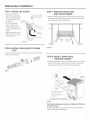
STEP 4: REMOVE TOEKICK
, Removethe 2 toekick screws and toekick. Set aside for use in
Step 2!.
Toekick Screws
Tip: Make sure door opens and closes smoothly.
Check door opening and closing. If door does not open easily or
falls too quickly, check spring cable routing. The cable is held in
place by "shoulders" on the pulley. Check to be sure cable has
not slipped over the pulley shoulders and isrouted as shown.

Dishwasher Installation
STEP 5: INSTALL 90 ° ELBOW
, Thread 3/4" GHT90°
elbow onto water valve.
Ensure rubber gasket is
located between valve
and elbow, Water Valve
Bracket
, Do not overtighten \
elbow. Water valve
bracket could bend or
water valve fitting could
break.
, Position the end of the
elbow to face the rear of
the dishwasher.
Figure K
Front of dishwasher
90 ° 3/4"
GHT Elbow
Fill Hose
STEP 7: POSITION WATER LINE
AND HOUSE WIRING
, Position water supply line and house wiring on the floor of
the opening to avoid interference with base of dishwasher
and components under dishwasher.
Line Wiring
STEP 6: INSTALL DRAIN HOSE TO DRAIN
LOOP
Connect drain loop end to drain hose using the screw clamp
as shown in the figure.
Figure L
Figure M
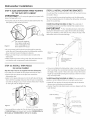
STEP 8: INSTALL DRAIN HOSE,
THROUGH CABINET
, Position dishwasher in front of cabinet opening. Insert drain
hose into the hole in cabinet side. If a power cord is used,
guide the end through a separate cabinet opening.
i J
Insulation
Blanket
f
Line
/
Ensure drain hose is not
twisted or pinched
Maximum drain hose
length is 15'
Do not disconnect or remove high
drain loop from left side of dishwasher
Figure N
Tip: Prevent unnecessary service call charges for fill, drain
or noise concerns.
Position utility lines so they do not interfere with anything
under or behind the dishwasher.

Dishwasher Instollotion
STEP 9: SLIDE DISHWASHER THREE-FOURTHS
OF THE WAY INTO CABINET
IMPORTANT- oonotpushagainstfrontpanelwith
knees. Damage will occur.
. Grasp the sides of the front panel and slide dishwasher into
the opening a few inches at a time.
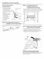
STEP li: INSTALL MOUNTING BRACKETS
You will need the mounting brackets and 2 #8 hex-head screws
set aside in Step 1.
You must install the mounting brackets onto the dishwasher
tub frame top or sides prior to sliding the dishwasher into place
under the countertop.
Install mounting brackets on top if the underside of
countertop iswood or wood-like material that accepts screws:
IMPORTANT - Afterinstalling bracketsandbefore
closing the dishwasher door, adjust the brackets by bending
them up as needed, so that they do not contact the top of the
dishwasher door and cause damage.
Figure O
Do not push against
front door panel with
knee. Damage to the
door panel will occur.
. Asyou proceed, pull the drain hose through the opening
under the sink. Stop pushing when the dishwasher extends
about 6 inches forward of adjacent cabinets.
. Make sure drain hose isnot kinked under or behind the
dishwasher.
. Make certain the house wiring, drain lineand water line do
not interfere with components under dishwasher.
STEP 10: INSTALL TRIM PIECES
(on some models)
Skip this step if trim is not supplied with the dishwasher.
Inthis step you will need the trim pieces set aside in Step 1.
. Position the trim pieces so the lips face toward the
dishwasher door.
, Select a trim piece and press it onto the left side tub flange.
Start with the top edge and press the trim piece completely
onto the tub flange as you move towards the bottom. Repeat
for the right side tub flange trim piece.
_J -
)
Figure P
Fully seat to tub flange
If you would like to order the Trim Kitfrom GEService, please
call 800.GE.Cores and request part number WD08×10094 for
BB models or WD08×10096 for WW or CCmodels.
Top Mounting
#8 Bracket
Screw
Dis
tub frame
Bracket
Bend and break here
after installing if
counter has ashort
overhang.
. If you are installing the dishwasher under a counter with a
short overhang, the countertop brackets may extend beyond
the edge of the counter. If this is the case, remove the excess
length by repeatedly bending the brackets at the front notch
only until they break.
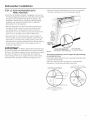
Install mounting brackets on sides if the countertop is
granite or similar material that will not accept wood screws:
, Break off front portion of the tab with pliers at the location
shown, prior to attaching to dishwasher.
. Position the left-hand side bracket as shown. Repeat with the
right bracket.
Side Mounting
Dishwasher---___
tub frame -_
#8 Bracket
screw as %
supplied M,
Do not pinch
the latch
wires in
#8 bracket
screw
'/,,,"%
i ub trim
Do not screw into
cabinet face frame
Bend and break
here if necessary
I
I
I
Bracket

Dishwasher Installation
STEP 12: PUSH DISHWASHER INTO
FINAL POSITION
. Checkthe tub insulation blanket, if equipped, to be sure it is
smoothly wrapped around the tub. It should not be "bunched
up" and it must not interfere with the door springs. If the
insulation is "bunched up" or interfering with the springs,
straighten und recenter the blanket prior to sliding the
dishwasher into its finul position.
. Slidethe dishwusher into the final position by pushing on
the sides of the door panel. Do not push or pull the door
in a purtiully open or closed position when moving the
dishwasher. Do not use a knee or push on the center of the
panel. If you do, damage to the panel will likely result.
. The dishwusher is in the final position when the edges of
the front panel ore flush with the adjacent cabinets and the
dishwusher is centered in the cabinet opening. Check that
the dishwasher issqu(]rely positioned in the cabinet opening
(it both the top and the bottom of the (]ppli(]nce prior to
mounting to the cabinet.
IM PO RTANT - Beforeopening thedishwasherdoor,
becertaintheedgesofthedishwasherdoorpanelorebehind
thefaceoftheadjacentcabinetand notup againstthecabinet
face.RefertoFigureQ.Ifthedishwasherdoorisopened
when theedge ofthedoorisagainstthefaceofthecabinet,
dishwasherdoordamage and cabinetdamage willoccur.
. Open and close the dishwasher door to be sure it oper(]tes
smoothly, and does not rub on the adjacent cabinet.
/
J
Door
fits and
swings
bac!_
behind
cabinet
frame \
Correct ........
Alignm_
Incorrect Alignment Door catches
Figure Q will result in door damage on cabinet frame
Tip: Prevent unnecessery service charges for panel damage
or wash performance.
Check dishwasher alignment prior to opening dishw(]sher door
to prevent panel damage.
ivl(]kesure utility lines ore not trapped or crushed behind
dishw(]sher. Crushed lines will restrict w(]ter flow.
Check that tub trim does not
contact the door at all points
m Tub frame
X Tub trim
Door
_ ....... Handle
Tub trimmay be trimmedif
necessarytoensureproperdoor
operation
Do not allow tub trim to get
trapped by or come into contact
with the door
Tub trim
trapped

Dishwasher Installation
STEP 13: LEVEL DISHWASHER
IM PORTANT = Dishwasher must be level for proper
dish rack operation, wash performance and door operation.
The dishwasher must be leveled left to right and front to back.
This ensures the dish racks will not roll in or out on their own,
circulation water will flow to the pump inlet, and the door will
close without hitting the side of the tub.
, Remove the lower dish rack and place a level on the door and
lower rack track as shown in Figure R.
. Adjust the level of the dishwasher by individually turning the 4
legs on the bottom of the dishwasher as illustrated in Figure S.
Ensureall 4 legs arefirmly in contact with the floor.
. The dishwasher is properly leveled when the level indicator is
centered left to right and front to back. Also, the dishwasher
door should close without hitting the side of the tub.
. Replace the lower rack.
Tip: Prevent unnecessary service charges. Verify dishwasher
is leveled.
Pullthe dish racks half way out. They should stay put. Open
and close the door. The door should fit in the tub opening
without hitting the side of the tub. If the racks roll on their own,
or the door hits the side of tub, relevel the dishwasher.
Figure R
Check
Front
to Back
Check
Level
Side
to Side
Figure S
Turn Legs
to Adjust //
J
lo

Dishwasher Installation
STEP 14: POSITION DISHWASHER, SECURE
TO COUNTERTOP OR CABINET
Inthis step you will need the 2 Phillipsspecial head screws
from the screws set aside in Step 1.
The dishwasher must be secured to the countertop or the
cabinet sides. When the underside of the countertop iswood,
use Method 1. UseMethod 2 when the underside of the
countertop is made of a material, such as granite, that will not
accept wood screws.
IMPORTANT - Preventdoor panel and control
panel damage. Dishwasher must be positioned so the front
panel and control panel do not contact the adjacent cabinets
or countertop. Mounting screws must be driven straight and
flush. Protruding screw heads could scratch the door panel or
control panel and interfere with door operation.
Method 1
Secure dishwasher to underside of wood countertop.
. Recheck alignment of the dishwasher in the cabinet, Referto
Steps 12 and 13. Door panel and/or control panel must not
hit cabinets or countertop.
. Fasten the dishwasher to the underside of the countertop
with the 2 Phillips special head screws. Refer to FigureT.
Make certain screws are driven straight and flush to prevent
panel damage,
• Install plug buttons to the side of the tub well in the holes
provided.
Brackets Wood Countertop
/ _ .-
"ill
Method 2
Secure dishwasher to cabinet sides.
. Recheck alignment of the dishwasher in the cabinet. Refer to
Steps 12 and 13. Door panel and/or control panel must not
hit cabinets or countertop.
. Fasten the dishwasher to the adjacent cabinets with the 2
Phillips special head screws provided. Referto Figure U. Make
certain screws are driven straight and flush to prevent panel
damage. Donot screw into the cabinet face frame.
. Install plug buttons to the side of the tub well in the holes
provided.
Solid Surface Countertop
//
Figure U
. Re-check that the dishwasher is squarely positioned in the
cabinet at both the top and bottom of the appliance after
mounting to the cabinets/countertop. Adjust if necessary.
. Confirm all leveling legs are in contact with the floor to
prevent the dishwasher from rocking and ensure proper door
and latch operation
STEP 15: CONNECT WATER SUPPLY
Connect water supply line to 90°elbow.
If using a flexible braided hose connection:
. Attach nut to 90° elbow using an adjustable wrench.
If using a copper tubing connection:
. Slide compression nut, then ferrule over end of water line.
. Insert water line into 90° elbow.
. Slide ferrule against elbow and secure with compression nut.
IMPORTANT - Check to be surethatdoor spring
and/or door springcabledo not rub or contactthe fillhose or
water supply line,
Test by opening and
closing the door.
Reroute the water
supply lines if a
rubbing noise or
interference
occurs.
Hot Water
Supply Line
no rlk_, _ Compression
....... \. °tX
Ferrule
Figure V
Bottom Left Side
11

Dishwasher Installation
STEP 16: CONNECT DRAIN LINE
The molded end of the drain hose will fit 5/8" through 1"
diameter inlet ports on the air gap, waste tee or disposer.
. Determine size of inlet port.
. Cut drain hose connector on the marked line, if required,
to fit the inlet port.
Figure W
Cutting Line
/
,s/83
/
IMPORTANT: Do not cut corrugated
portion of hose
. If a longer drain hose isrequired and you did not purchase
drain hose WD24×10065, add up to 66" length for a total of
14/4"(12 feet) to the factory-installed hose. Use 5/8" or 7/8"
inside diameter hose and a coupler to connect
the 2 hose ends.
Secure the
connection _
with hose
clamps.
Figure × Hose Clamp
Hose Clamp
Coupler
NOTES:
. DRAIN CONNECTION HEIGHT ISNOTTO EXCEED 72" ABOVE
BOTTOM OF DISHWASHER.
. TOTAL DRAIN HOSE LENGTH MUST NOT EXCEED 12 FEET FOR
PROPER DRAIN OPERATION.
. Connect drain line to air gap, waste tee or disposer
using the previously determined method. Secure hose
with a screw-type clamp.
Method 1- Air gap with waste tee or disposer
Waste TeeInstallation
Figure Y
Disposer Installation
Method 2 - "High drain loop" with waste tee or disposer
With this method you will need the drain hose hanger set aside
in Step 1.
Fasten drain hose to underside of countertop with the provided
hanger.
__ Drain Hose Hunger
WasteTeeInstallation
Figure Z
Disposer Installation
IMPORTANT - When connecting drain line to
disposer, check to be sure that drain plug has been removed.
DISHWASHERWILL NOTDRAINIF PLUGISLEFTIN PLACE.
4 Remove
Drain
Plug
Tip: Avoid unnecessary service call charges for a no drain
complaint.
Make sure excess drain hose has been pulled through
the cabinet opening. This will prevent excess hose in the
dishwasher cavity from becoming kinked or crushed by the
dishwasher.
12

Dishwasher Installation
STEP 17: CONNECT POWER SUPPLY
If a power cord with plug is already installed proceed to
Step 18.
WARNING:
If housewiringisnot 2-wirewithground,agroundmustbe
providedbythe installer.Whenhousewiring isaluminum,be sure
to useUL-Listedanti-oxidantcompoundand aluminum-to-copper
connectors.
A ADVERTENCIA:
Sielcableadodom_sticonocuentaconuncablede 2hiloscon
conexi6natierra,un instaladordeberealizarunaconexi6na tierra.
Cuandoelcableadodom_sticoesdealuminio,aseg0resedeusar
uncompuestoantioxidanteyconectoresdealuminioa cobre
aprobadosporUL.
In this step you will need the junction box cover and the
#10 Hex head screw from the screws set aside in Step 1.
. Secure house wiring to the back of the junction box with a
strain relief.
. Locate the 3 dishwasher wires, (white, black and green) with
the stripped ends coming out of the ACjumper. Use ULlisted
wire nuts of appropriate sizeto connect incoming ground to
green, white to white and black to black.
. Install the junction box cover using #10 hex head screw.
Check to be sure that wires are not pinched under the cover.
. Make sure that the junction box cover is resting on the
mounting bracket.
NOTE:Do not remove the
Junction Box Bracket.
Ground
White
AC
Jumper
Ground
Screw
Black
Figure AA
NOTE:All ground screws, brackets and wires must remain
intact.
STEP 18:PRETEST CHECKLIST
Review this list after installing your dishwasher to avoid
charges for a service call that is not covered by your
we rra nty.
. Check to be sure power is OFF.
.Open door and remove all foam and paper packaging.
. Locate the Owner's Manual set aside in Step 1.
.Readthe Owner's Manual for operating instructions.
. Check door opening and closing. If door does not open and
close freely, check for proper routing of spring cable over
pulley. If door drops or closes when released, adjust spring
tension. SeeStep 2.
. Check to be sure that wiring issecure under the dishwasher,
not pinched or in contact with door springs or other
components. SeeStep 17.
. Check door alignment with tub. If door hits tub, level
dishwasher. See Step 13.
. Pull lower rack out, about halfway. Check to be sure it does
not roll back or forward on the door. If the rack moves, adjust
leveling legs. See Step 13.
. Check door alignment with cabinet. If door hits cabinet,
reposition dishwasher. See Step 12.
. Check that door spring does not contact water line, fill hose,
wiring or other components. SeeStep 12.
.Verify water supply and drain lines are not kinked or in
contact with other components. Contact with motor or
dishwasher frame could cause noise.
.Turn on the sink hot water faucet and verify water
temperature. Incoming water temperature must be between
120°Fand 140°F.A minimum of 120°F temperature is
required for best wash performance. See"Prepare Hot Water
Line," page 5.
.Add 2 quarts of water to the bottom of the dishwasher to
lubricate the pump seal.
.Turn on water supply. Check for leaks.Tighten connections if
needed.
. Remove protective film if present from the control panel and
door.
. Check that tub trim does not contact the door.
13

Dishwasher Installation
STEP 19: DISHWASHER WET TEST
.Turn on power supply or plug power cord into outlet,
if equipped.
. Select u cycle to run and push the Start/Reset pad.
. Ensurethe door is latched. Dishwasher should start.
. Checkto be sure that water enters the dishwasher. If water
does not enter the dishwasher, check to be sure that water
and power are turned on.
. Checkfor leaks under the dishwasher. If a leak isfound, turn
off power at the breaker, and then tighten water connections.
Restore power after leak is corrected.
. Checkfor leaks around the door.A leak around the door could
be caused by door rubbing or hitting against
adjacent cabinets. Reposition the dishwasher if necessary.
SeeStep 12.
. Pressend hold the Start/Reset pad for 3 seconds to cancel
the cycle. The unit will begin to drain. Check drain lines. If
leeks ere found, turn off power at the breaker end correct
plumbing us necessary. Restorepower after corrections ere
made. See Steps 6,7,8, 9 end 16.
. Open dishwasher door and make sure oil of the water has
drained. If not, check that disposer plug has been removed
end/or air gap is not plugged. Also check drain hose to be
sure it is not kinked underneath or behind dishwasher. See
Step 16.
. PressStart/Reset pad once again end run dishwasher
through another cycle. Check for leeks end correct if
required.
. Repeat this step us necessary.
STEP 20: POSITION SOUND BARRIER
AND INSULATION
Ion some models}
Skip this step if the sound barrier is not assembled to the
dishwasher.
. Locate the sound insulation package inside the dishwasher.
. Locate the control box.
Control
Box
. Peeloff the paper from the insulation.
. Apply the insulation to the underside of the control box and
flush with its front face as shown.
Insulation shown adhered to bottom edge of the control
box, flush with the front face, and correctly placed along
dishwasher bottom.
14

Dishwasher Installation
STEP 21: REPLACE TOEKICK
. Placetoekick against the legs of the dishwasher.
Figure CC
Screws
. Align the toekick with the bottom edge and make sure it is
against the floor.
. Insert and tighten the 2 toekick attachment screws. The
toekick should stay in contact with the floor.
. When reinstalling the toe kick on models with a sound barrier,
ensure that the bottom edge isflush with the floor. Any
excess material should be tucked up behind the outer door.
Tip: Reduce sound from under the dishwasher.
Hake sure toekick is against floor.
STEP 22: CHECK THE FOLLOWING
. Tub trim does not interfere with the door
. Dishwasher is square and level at both the top and bottom of
the cabinet opening, with no twisting or distortion of the tub
or door
. All 4 legs of the dishwasher are firmly in contact with the floor
. Drain hose isnot pinched between the dishwasher and
adjacent cabinets or walls
. Tub trim isfully seated on the tub flange
STEP 23: LITERATURE
. Besure to leave complete literature package, these
Installation Instructions and product samples and/or coupons
with the consumer.
15

SPECIFICATIONS SUBJECT TO CHANGE WITHOUT NOTICE
GEAppliances
General Electric Company
Louisville, Kentucky/40225
GEAppliances.com
© 2014 General Electric Company

Appareils m@nagers
Directivesd'instailation
Lave-vaisselle encastr@
Pourtoute question, composez le 1.800.561.3344 ou visitez notre site Web:
www.electromenagersge.ca
AVANT DE COMMENCER
Veuillez lire attentivement toutes lesdirectives
qui suivent.
A AVERTISSEMENT :
. Pour r_duire lesrisques de choc 61ectrique,d'incendie
ou de blessures, I'installateur doit s'assurer que le lave-
vaisselle est compl_tement encastr6 au moment de
I'installation.
. POURVOTRESECURITEPERSONNELLE:Enlevez le fusible
ou d_clenchez le disjoncteur au panneau de distribution
principal avant de commencer I'installation. N'utilisez pas
une rallonge 61ectrique ou un adaptateur de fiche avec
cet appareil.
Un branchement inad_quat du conducteur de mise 6 la
terre peut pr6senter des risques de choc 61ectrique.Si
vous n'@tespas certain que I'appareil est correctement
mis 6 la terre, consultez un r6parateur ou un 61ectricien
qualifi&
Sile cSblage61ectriquede la r6sidence n'est pasconstitu6
de deux ills plus un fil de mise6 la terre, I'installateur dolt
installer un fil de mise 6 la terre. SilecSblage 61ectriquede
la r6sidenceest en aluminium, utilisezunagent antioxydant
et desconnecteurs pour raccords <<aluminium-cuivre>>
homologu6s UL
A, ATTENTION :
N'enlevez pas la base de bois avant d'@trepr@t6 installer
le lave-vaisselle. Sivous enlevez la base de bois, le lave-
vaisselle pourrait basculer Iorsque vous ouvrez la porte.
POUR VOTRE SI_CURITI_
Veuillez life et observer toutes les raises en gerde
(AVERTISSEMENTet ATTENTION}donn_es dens les pr@sentes
directives. Pour effectuer I'instelletion d_crite dens les pr_sentes
directives, il feut porter des gents et des lunettes de s@curit&
IMPORTANT =Observeztouslescodeset
ordonnances envigueur.
. Note 6 I'installeteur - Veuillez laisser les pr6sentes directives
au consommateur pour I'inspecteur local.
. Note au consommeteur - Veuillez conserver les pr6sentes
directives avec votre Manuel d'utilisation pour consultation
ult@ieure.
. Comp@tences requises - L'installation de ce lave-vaisselle
exige des comp@ences de base en m_canique, en 61ectricit6
et en plomberie. L'instelleteur est responseble de In quelit@
de I'instellation. Toute d@feillance du produit ettribuable
a une installation inadequate n'est pes couverte par la
garantie de GE.Reportez-vous a la gerantie du produit.
. Dur@ede I'installation - Entre i et 3 heures. L'installation
d'un nouveau lave-vaisselle exige plus de temps que
le remplacement d'un ancien module.
IM PORTANT - Lelave-vaisselleDOIT@treinstall6de
mani@e 6 cequ'ilpuisse@tresortide sonemplacement sides
r@parationssontn6cessaires,
IIimported'userde prudencelorsquel'appareilestinstall6
ou d6plac6afinde pr6venirl'endommagementdu cordon
d'alimentation.
Si le lave-vaisselle que vous avez request endommag6,
communiquez imm6diatement avec votre d@aillant ou
I'entrepreneur en construction.
Accessoiresfacultatifs - Reportez-vousau Manueld'utilisationpour
connattrelesensemblespour panneau d6coratifpersonnalis6offerts.
oo
VEUILLEZ LIRE ATTENTIVEMENT
ET CONSERVER CES DIRECTIVES.
,, .... ,, \
'..,._
ImprimdauxEtats-Unis 31-3154£ 09-14 GE

Pr6paration pour I'installation
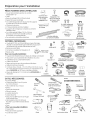
PIt CESFOURNIES DANS UEMBALLAGE:
. Couverclede la bottedejonction etvis 6 t6te
hexagonalen° 10
. Collier
. Boyaudevid(]nge (198cm/78 po de long)
. Supportde tw(]u devid(]nge)
. 2vis(3t6te hex(]gon(]leno 8-28 pourfixer lessupports
(]uc(]dredeI(]cuvedu I(]ve-v(]isselle
. 2 Boutonsde bouchon
. 2 MouluresI(]t6r(]les(cert(]insmod61es)
. 2supportsde mont(]gepourcomptoirs ou aarmoires
I(]t6r(]lesen bois
. 2vis(3t6te sp6ciaalePhillipsn°8-28 x 25,8mm
(5/8po)pourfixer leI(]ve-v(]isselle(]udessous
du comptoirou (]rmoiresI(]t6r(]les
. Documentaation,6ch(]ntillonset(ou)bans
\
Couvercle de la
boTte de jonction
et vis 6 t_te
hexogonole n°10
Support de tuyou
de vidange
?
Vis 6 t_te
hexagonale n° 10
de 12,7 mm {1/2 po)
de long pour boTte
dejonction
(sur certoins modules)
Collier
??
Vis 6 t@te hexagonole
n° 8 pour support de
montage
Supports de
montage
MATERIEL NI CESSAIRE:
. Coudede 90°(19,1mm [3/4po]filetpour tuy(]ud'(]rros(]ge
dej(]rdin (_uneextr6mit6 et I'(]utreextr6mit6conquepour le
r(]ccordement(_I(]conduite d'(]liment(]tioneneaau)
. Rub(inpourjoints filet6s
. Connecteursvissaableshomologu6sUL(3)
. Rub(]n-caache
Pour une nouvelle installation:
Coude de 90°
Rubon-cache
(s'il y o lieu)
. Coupure(]nti-refoulementpourleboy(]ude vid(]nge,sin_cess(]ire
. RaaccordenTpour I(]plomberiede laar6sidence,slly aalieu
. C_ble61ectriqueoucordon d'aaliment(]tion
. Colliers(_viss(]nsfin
. B(]gue(]nti-tr(]ction pour ler(]ccordement61ectrique _-]
. Robinetd'(]rr6t(recomm(]nd6)
. Conduite d'e(]u chaaude- 9,5 mm (5/8 po) minimum, tuyaau
en cuivre (inclu(]nt I(] b(]gue et 1'6crou(3compression) ou laa
piece W×28×326 de GE,boy(]u m6t(]llique flexible.
. Boy(]ude vidaangede 5,7m(12 pi)de long WD24×10065,si
n6cessaaire Coupure
unti-refoulement
?
Roccord en T
Boyaudevidange
n
Boutons de
bouchon
Vis 6 t_te
sp_ciole
Phillips n°8
de 15,8 mm
(5/8 po) de long
Connecteurs
Robinet Ruban pour vissables (3)
d'arr_t joints filet6s
(s'il y a lieu)
C6ble 61ectrique (ou cordon
d'alimentation, s'il y a lieu)
Colliers (] vis sans fin
Conduited'eou
chaude
Bayou de vidange Raccord
focultatif de pour boyau
3,66 m 112pi) de videnge
Bugue anti-traction facultutif
OUTILS NI CESSAIRES:
. TournevisPhillips
. Tourne-6crousde6,3mm (2/4po)et
de 7,9mm (5/16po)
. CI66 molette de 15,2cm (6po)
. Niveaau
. Equerrede ch(]rpentier
. Rubaan(_mesurer
. Lunettesdes_curit6
. L(]mpedepoche
. Se(]upour recueillirI'e(]uIorsdu rinqaage
de I(]conduited'e(]u
. CI_(_douillede 23,8mm (15/16po)
(f(]cult(]tif- pour enleverlaabaasede bois)
, G(]nts
. Pince
, Pour une nouvelle installation:
. Coupe-tubes
. Perceuseetforetsappropri6s
. Jeude scies-cloche
Phillips
CI6 6 douille de
23,8 mm 115/16 pal
Lampe de poche
Gants
Tou
de 6,3 mm (1/4 po)
et de 7,9 mm (5/16 po)
Pince
CI66 molette
de 15,2 cm
16pal
Seau
Niveou
Coupe-tubes
I_querre de
charpentier
Ruban 6 mesurer

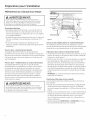
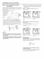
Preparation pour l'installation
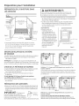
PRI_PARATION DE L'OUVERTURE DANS
LESARMOIRES
33-1/2 po to 34-3/4 po
du dessous du
comptoir au
plancher
Lemur du fond
doit _tre exempt
de tuyaux ou
de ills
AVERTISSEMENT:
Pourr_duirelesrisquesde choc_lectrique,d'incendieoude
blessures,I'installateurdoits'assurerque lelave-vaisselleest
compl_tementencastr_au momentdeI'installation.
. Lelave-vaisselle doit _tre install6 de faqon 6 ce que le boyau
de vidange mesure au maximum 3.66 m_tres (12 pieds) pour
assurer une vidange ad6quate.
. Ledessus, lesc6t6s et I'arri_re du lave-vaisselle doivent
_tre compl_tement dissimul6s 6 I'int@ieur de I'ouverture.
Lelave-vaisselle ne doit soutenir aucune pattie de la
61,0 cm
(24 po) min.
Figure A
. L'ouverture dans les armoires doit mesurer au mains
61,0 cm (24 po) de largeur et de profondeur, et environ
87,6 cm (34-!/2 po) de hauteur 6 partir du plancher
jusqu'au-dessous du comptoir.
structure des armoires.
DEGAGEMENTS:
. Dans le cas d'une
installation dans un
coin, veuillez pr@oir un
d6gagement d'au mains
5,1 cm (2 po) entre le lave-
vaisselle et lesarmoires, le
mur ou un aectrom6nager
adjacent. Veuillez pr@oir
un d6gagement d'au mains
72 cm (28-:3/8 po)6 I'avant
Armoires c3
1'6querre et
_d'aplomb
du lave-vaisselle pour
I'ouverture de la porte.
Reportez-vous a la
Figure B.
Comptoir
1,2pal
7/ S,1 cm(2 po) minimum pourI'ouverture de la porte
Figure B
E×IGENCES RELATIVES AU SYSTI_ME
DE VIDANGE
. Veuillezobserver lesordonnanceset lescodes Iocauxen vigueur.
. Leboyau de vidange doitavoir uneIongueur maximale de
3.66m_tres (12pieds).
REHARQUE:IIfaut installerune coupure anti-refoulement sile
raccord au broyeura d6chetsou au raccord enTsetrouve a mains
de 46 cm (18po)au-dessusdu plancher afin d'@iter un siphonage.
CHOI× DE LA MI_THODE DE VIDANGE
Letype d'installationde vidange d@end desconditions suivantes.
. Lesordonnances ou codes Iocauxen vigueurexigent-ils
une coupureanti-refoulement?
. Leraccord en Tsetrouve-t-il a mains de 46 cm (18po)
du plancher?
Sivous r_pondez OUI6 I'uneou I'autre de ces questions,
vous DEVEZutiliser la m_thode n° 1.
° Sivousr_pondez NON,vous pouvezemployer I'uneou I'autre
desm@hodes.
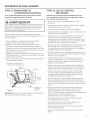
PRI'-_-PARATIONDES ARMOIRES
° Percezuntrou de 3,8cm (1-1/2po)de diam_tre dansla paroi de
I'armoirequi setrouve dans la partie ombr6edela FigureApour
leboyau de vidange.Assurez-vousque I'orificene pr6sente pas
d'ar@esvives.
IMPORTANT - Lorsquevous
branchezlebayoudevidange(3un
broyeurc]d6cheis,assurez-vousd'enlever
lebouchondevidange.LELAVE-VAISSELLE
41 nJevezle
bouchon
de vidange
NE POURRA PASSEVIDER SIVOUS LAISSEZLEBOUCHON EN PLACE,
FigureC
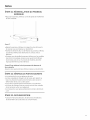
M_thode n° 1 - Coupure anti-refoutement avec raccord en T ou
broyeur 6 d_chets
IIfaut installer une coupure anti-refoulement Iorsqu'elle est exig_e par
les ordonnances et les codes Iocaux en vigueur. Cette coupure anti-
refoulement doit @treinstall@econform@ment aux directives donn@es
par le fabricant.
Crochet pour boyau devidange j._g Crochet pour boyau devidonge
Iql / (q_"_ I82cm
III ( fq:tI_S2;_o_
m,n III I Ti
118pal min JJL_ (18po)m_]_
Figure D
M@thode n° 2 - Boucle de vidange @lev@eavec raccord en T ou
broyeur a d@chets
Conseil: Pour @viter des frais de r(_paration inutiles.
Assurez-vous d'enlever le bouchon de vidange du broyeur 6
d6chets avant d'y brancher le boyau de vidange du lave-vaisselle.

Preparation pour I'installation
PRE PARATION DU C#,BLAGE E LECTRIOUE
AVERTISSEMENT:
POURVOTRESECURITEPERSONNELLE:Enlevezlefusibleou
d@clenchezledisjoncteurau panneaude distributionprincipal
avant de commencerI'installation.N'utilisezpasune rallonge
@lectriqueou un adaptateur defiche aveccet appareil.
Alimentation @lectrique
.Cet appareil doit _tre aliment6 par un courant de 120 Vet
60 Hz,et branch6 6 un circuit individuel correctement mis
6 la terre et prot6g_ par un disjoncteur de !5 ou 20 amperes
ou un fusible temporis6.
. Le c@ble61ectrique doit poss6der deux ills, plus un fil de mise
6 la terre, et r6sister 6 une temp@ature nominale de 75 °C
(176 °F).
. Sivotre alimentation 61ectrique ne r6pond pas 6 ces
exigences, appelez un 61ectricien agr66 avant de poursuivre
I'installation.
Mise 6 la terre- Branchement permanent
Cet appareil doit _tre branch6 6 un r6seau _lectrique
permanent mis 6 la terre. Sinon, il faut installer un conducteur
de raise 6 la terre avecles conducteurs du circuit et le brancher
6 la borne de raise 6 la terre du r6seau ou au fil de raise 6 la
terre de I'appareil.
Mise 6 la terre - ModUles dot_s d'un cordon d'alimentation
Cet appareil doit _tre mis 6 la terre. Encas de mauvais
fonctionnement ou de d6faillance, la raise6 la terre r6duira
les risques de choc 61ectrique en fournissant au courant
61ectrique un circuit de moindre r6sistance. Cet appareil est
dot6 d'un cordon d'alimentation poss_dant un conducteur
de raise 6 la terre et une fiche de raise 6 la terre. Lafiche
doit _tre branch6e clans une raise appropri6e, install6e et
raise 6 la terre en conformit6 avec tousles codes Iocaux et
ordonnances en vigueur.
A AVERTISSEMENT:
Un branchement inad_quat du conducteur de raise 6 la terre
peutpr@senterdesrisquesdechoc@lectrique.Sivousn'@tespas
certain que I'appareilestcorrectementmis6 laterre,consultez
unr@parateurouun @lectricienqualifi@.
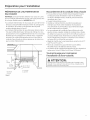
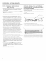
u -- E
z IAutreemplacement ?\
I possiblepourla prise i \
i de courant dans une i \
I armoire ac \
46 cm (18 po)
-- 46 cm i÷ laprise d_--_l
(18po) I cou@,tIS1
/1÷'-
15cm 16po) 15cm-_
7,6cm (3po)
des armoires
Mise 6 la terre
Noir
Figure E Blanc
Dons le cos des modules dot_s d'un cordon d'alimentotion:
Ne modifiez pas la fiche fournie avec I'appareil; si vous ne
pouvez pas la brancher dans la prise de courant, faites installer
une prise de courant appropri6e par un technicien qualifi6.
Preparation des ormoires et cheminement des ills
Lesills peuvent entrer dans I'ouverture du c6t_ droit, du c6t_
gauche, de I'arri@e ou du plancher dans la pattie ombr6e de
la Figure Eet de la FigureA.
Percez un trou de 3,8 cm (1-1/2 po) de diam_tre au maximum
pour le passage du cable 61ectrique.Le bard du trou doit
_tre lisse et arrondi. Lesills 61ectriques pour le branchement
permanent peuvent passer par le m_me trou que le boyau
de vidange et la conduite d'eau chaude, si c'est plus pratique.
Si le trou est pratiqu6 dans une paroi en m@al, les bards de
I'orifice doivent _tre recouverts d'un passe-fils pour prot6ger
les fils.
REMARQUE:Lecordon d'alimentation dot6 d'une fiche doit
passer par un autre trou.
Branchement _lectrique du lave-voisselle
Le branchement _lectrique s'effectue du c6t_ avant droit du
lave-vaisselle.
Dans lecas d'un branchement permanent, le c_ble doit _tre
achemin_ de la faqon indiqu_e 6 la Figure E.Lec_ble doit
avoir une Iongueur minimale de 61 cm (24 po)6 partir du tour
arri@e.
Dans lecas d'un branchement avec un cordon d'alimentation,
installez une prise de courant raise 6 la terre 6 trois broches
sur la paroi de I'armoire adjacente, entre 15 cm (6 po) et
46 cm (18 po) de I'ouverture, et entre 15 cm (6 po) et 46 cm
(18 po) du plancher.
Utilisez uniquement W×09×70910 ou W×09×70911 Trousse
de cordon d'alimentation pour lave-vaisselle.
La page est en cours de chargement...
La page est en cours de chargement...
La page est en cours de chargement...
La page est en cours de chargement...
La page est en cours de chargement...
La page est en cours de chargement...
La page est en cours de chargement...
La page est en cours de chargement...
La page est en cours de chargement...
La page est en cours de chargement...
La page est en cours de chargement...
La page est en cours de chargement...
-
 1
1
-
 2
2
-
 3
3
-
 4
4
-
 5
5
-
 6
6
-
 7
7
-
 8
8
-
 9
9
-
 10
10
-
 11
11
-
 12
12
-
 13
13
-
 14
14
-
 15
15
-
 16
16
-
 17
17
-
 18
18
-
 19
19
-
 20
20
-
 21
21
-
 22
22
-
 23
23
-
 24
24
-
 25
25
-
 26
26
-
 27
27
-
 28
28
-
 29
29
-
 30
30
-
 31
31
-
 32
32


GE GDF520PSJ0SS Guide d'installation
- Catégorie
- Lave-vaisselle
- Taper
- Guide d'installation
- Ce manuel convient également à
dans d''autres langues
- English: GE GDF520PSJ0SS Installation guide