ZyXEL XGS3600-26F Guide de démarrage rapide
- Catégorie
- Commutateurs réseau
- Taper
- Guide de démarrage rapide
Ce manuel convient également à


Note: Go to www.zyxel.com to view this product’s
documentation and certifications.

ENGLISH
1
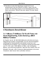
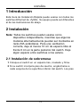
1 Introduction
This Quick Start Guide is for use with all ZyXEL Ethernet
switches. Your device may differ from the illustrations below.
2 Installation
All switches can be used as a standalone device while some
can alternatively be mounted on standard EIA racks.
Note: For proper ventilation, allow at least 4 inches
(10 cm) of clearance at the front and 3.4 inches
(8 cm) at the back of the switch. Leave space
between switches if stacking.
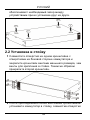
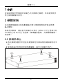
2.1 Desktop Installation
1 Set the switch on a smooth, level surface.
2 If your switch comes with unattached rubber feet, attach
them to each corner on the bottom of the switch. These
ENGLISH

2
ENGLISH
rubber feet help protect the switch from shock or vibration
and ensure space between devices when stacking.
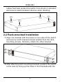
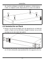
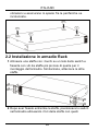
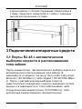
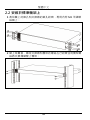
2.2 Rack-mounted Installation
1 Align one bracket with the holes on one side of the switch
and secure it with bracket screws smaller than the rack-
mounting screws. Similarly, attach the other bracket.
2 After attaching both mounting brackets, position the switch
in the rack by lining up the holes in the brackets with the

ENGLISH
3
appropriate holes on the rack. Secure the switch to the
rack with the rack-mounting screws.
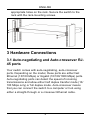
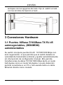
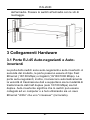
3 Hardware Connections
3.1 Auto-negotiating and Auto-crossover RJ-
45 ports
Your switch comes with auto-negotiating, auto-crossover
ports. Depending on the model, these ports are either fast
Ethernet (10/100 Mbps) or Gigabit (10/100/1000 Mbps) ports.
Auto-negotiating ports can detect the speed of incoming
transmissions and allow either half duplex transfer mode (10/
100 Mbps only) or full duplex mode. Auto-crossover means
that you can connect the switch to a computer or hub using
either a straight-through or a crossover Ethernet cable.

4
ENGLISH
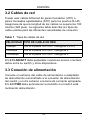
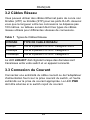
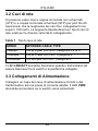
3.2 Network Cables
You can use unshielded twisted pair (UTP) or shielded
twisted-pair (STP) Ethernet cables for RJ-45 ports. Make sure
the cable length between connections does not exceed 100
meters (328 feet). The following table describes the types of
network cable used for different connection speeds.
Table 1 Network Cable Types
The LNK/ACT LED should flash when data is being sent
between your switch and a connected device.
3.3 Power Connection
Connect one end of the supplied power cable or power
adaptor to the power receptacle on the switch and the other
end to the appropriate power source. The PWR LED should
turn steady on if the switch is receiving power.
SPEED NETWORK CABLE TYPE
10Mbps 100 Ω 2-pair UTP/STP Category 3,4 or 5
100Mbps 100 Ω 2-pair UTP/STP Category 5
1000Mbps 100 Ω 4-pair UTP/STP Category 5

ENGLISH
5
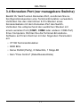
3.4 Console Port (Managed Switches Only)
If your switch has a console port, you can use a terminal
emulator for local management. Connect the male 9-pin end
of a console cable to the console port of the switch. Connect
the female end to a serial port (COM1, COM2 or other COM
port) of your computer. Configure the computer with terminal
emulation software to the following parameters:
• VT100 terminal emulation
• 9600 bps
• No parity, 8 data bits, 1 stop bit
• No flow control
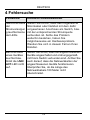
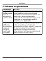
4 Troubleshooting
PROBLEM CORRECTIVE ACTION
None of the
LEDs are on
when the power
is connected.
Verify that the included power or cable
adaptor is connected to the switch's power
receptacle and appropriate power source.
If the error persists, you may have a
hardware problem and should contact your
vendor.
The LNK/ACT
LED does not
light up or flash
when a device
is connected.
Verify that the attached device(s) is turned on
and properly connected to your switch. Also
make sure the Ethernet cards are working on
the attached devices. Verify that the network
cable does not exceed 100 meters.

6
ENGLISH

DEUTSCH
7
1 Einleitung
Diese Kurzanleitung dient der Verwendung aller ZyXEL
Ethernet-Switche. Das Aussehen ihres Gerätes kann von den
unten gezeigten Abbildungen abweichen.
2 Installation
Note: Alle Switche können als Einzelgeräte verwendet
werden, wobei einige alternativ in 19 Zoll
Standardracks montiert werden können. Für eine
ausreichende Belüftung sollte vor dem Switch ein
Freiraum von mindestens 10 cm und hinter dem
Switch ein Freiraum von mindestens 8 cm gelassen
werden. Wenn Sie Switche übereinander
anordnen, lassen Sie einen Freiraum zwischen den
Geräten.
2.1 Tisch-Montage
1 Legen Sie den Switch auf eine glatte, ebene Unterlage.
2 Sollte Ihr Switch mit nicht montierten Gummifüßen
geliefert worden sein, bringen Sie diese an jeder Ecke der
Geräteunterseite an. Diese Gummifüße dienen dem
Schutz vor Stößen und Vibrationen und gewährleisten den
DEUTSCH

8
DEUTSCH
Freiraum zwischen den Geräten wenn diese übereinander
angeordnet werden.
2.2 Rack-Montage
1 Richten Sie die Bügel an den seitlich angeordneten
Löchern des Switch aus und sichern Sie diese mit den
dafür vorgesehenen Schrauben, die kleiner sind, als die
Schrauben die dafür verwendet werden, um das Gerät im
Rack zu befestigen. Gehen Sie analog dazu mit dem
anderen Bügel vor.

DEUTSCH
9
2 Nachdem beide Montagebügel angebracht sind,
positionieren Sie den Switch im Rack, indem Sie die
Löcher der Montage-bügel an den Montagelöchern des
Rack ausrichten. Sichern Sie den Switch mit den Rack-
Schrauben.
3 Hardware-Anschlüsse
3.1 10Base-T/100Base-TX RJ-45 Ports mit
Auto-Negotiating, Auto-Sensing- (MDI/
MDIX)-Funktion
Ihr Switch ist mit 10/100/1000 Mbit/s-RJ-45-Ports mit Auto-
Negotiating-Funktion ausgestattet, die die Geschwindigkeit
empfangener Datenpakete automatisch erkennen und
entsprechend einstellen. Sie ermöglichen Datentransferraten
von 10, 100, oder 1000 Mbit/s im Halb- oder Vollduplex-
Modus. Auto-Sensing bedeutet, dass Sie den Switch über ein
Straight-Through- oder Crossover-Netzwerkkabel mit einem
Computer oder einem Hub verbinden können.

10
DEUTSCH
3.2 Netzwerkkabel
Für RJ-45-Ports können Sie UTP (unshielded twisted-pair)-
oder STP (shielded twisted-pair)-Netzwerkkabel verwenden.
Achten Sie darauf, dass die Kabellänge zwischen den
Anschlüssen weniger als 100 Meter beträgt. Die folgende
Tabelle verdeutlicht die für die verschiedenen
Geschwindigkeiten verwendeten Netzwerkkabel-typen
Table 1 Netzwerkkabeltypen
Die LNK/ACT-LED sollte aufblinken, wenn Daten zwischen
Ihrem Switch und einem angeschlossenen Gerät versendet
werden.
3.3 Stromversorgung
Verbinden Sie das eine Ende des mitgelieferten Stromkabels
oder Netzteils mit dem dafür vorgesehenen Anschluss am
Switch. Verbinden Sie nun das andere Ende mit der
entsprechenden Stromquelle. Die PWR-LED sollte leuchten,
wenn der Switch mit Spannung versorgt wird.
GESCHWINDIGKEIT NETZWERKKABELTYP
10Mbps 100Ω 2-paarig UTP/STP Cat. 3,4 oder
5
100Mbps 100Ω 2-paarig UTP/STP Cat. 5
1000Mbps 100Ω 4-paarig UTP/STP Cat. 5

DEUTSCH
11
3.4 Konsolen-Port (nur managebare Switche)
Besitzt Ihr Switch einen Konsolen-Port, so können Sie zu
Konfigurationszwecken eine Terminal-Emulation verwenden.
Verbinden Sie den männlichen 9-Pin-Stecker eines
Konsolenkabels mit dem Konsolen-Port des Switch.
Verbinden Sie entsprechend den weiblichen Stecker mit
einem seriellen Port (COM1, COM2 oder anderer COM-Port)
Ihres Computers. Richten Sie die Terminal-Emulations-
Software auf Ihrem Rechner mit den folgenden Parametern
ein:
• VT100 Terminal-Emulation
• 9600 Bit/s
• Keine Parität (Parity), 8 Datenbits, 1 Stopp-Bit
• Kein "Flow Control" (Datenflusskontrolle)

12
DEUTSCH
4 Fehlersuche
PROBLEM KORREKTURMASSNAHME
Nach Anschluss
der
Stromversorgun
g leuchtet keine
der LEDs
Stellen Sie sicher, dass das mitgelieferte
Stromkabel oder Netzteil mit dem dafür
vorgesehenen Anschluss am Switch, bzw.
mit der entsprechenden Stromquelle
verbunden ist. Sollte das Problem
weiterhin bestehen, haben Sie
möglicherweise ein Hardwareproblem.
Wenden Sie sich in diesem Fall an Ihren
Händler.
Bei Anschluss
eines Gerätes
leuchtet bzw.
blinkt die LNK/
ACT-LED nicht
auf.
Stellen Sie sicher, dass die angeschlossenen
Geräte angeschaltet und ordnungsgemäß
mit Ihrem Switch verbunden sind. Achten Sie
auch darauf, dass die Netzwerkkarten der
angeschlossenen Geräte funktionieren.
Überprüfen Sie, ob die Länge des
Netzwerkkabels 100 Meter nicht
überschreitet.

ESPAÑOL
13
1 Introducción
Esta Guía de Instalación Rápida puede usarse con todos los
switches Ethernet de ZyXEL. Su equipo puede ser diferentes
al de las ilustraciones de abajo.
2 Instalación
Note: Todos los switches pueden usarse como
dispositivo independiente, mientras que algunos
modelos alternativamente pueden ser montados en
racks EIA estándares. Para una ventilación
correcta, deje al menos 10 cm de espacio libre al
frente 8 cm en la parte posterior del switch. Deje
algún espacio entre switches si los estaca.
2.1 Instalación de sobremesa
1 Coloque el switch en un espacio liso, nivelado y firme.
2 Si su switch incorpora pies de caucho, engánchelos a
cada esquina de la superficie inferior del switch. Los pies
ESPAÑOL

14
ESPAÑOL
de caucho protegen el switch de golpes o vibraciones y
crean un espacio entre dispositivos en caso de estacar.
2.2 Instalación en Rack
1 Alinee uno de los anclajes con los agujeros en un lado del
switch y fíjelo con los tornillos. Haga lo mismo con el otro
anclaje en el otro lado del switch.
2 Después de colocar los dos anclajes posicione el switch
en el rack alineando apropiadamente los agujeros de los

ESPAÑOL
15
anclajes con los agujeros del rack. Fije el switch al rack
con los tornillos de fijación al rack.
3 Conexiones Hardware
3.1 Puertos 10Base-T/100Base-TX RJ-45
autonegociables, (MDI/MDIX)
autodetectables
Su switch incorpora puertos RJ-45 10/100/1000 Mbps con
auto negociación, lo que permite que el switch detecte la
velocidad de transmisión entrante y ajustar automáticamente
sin intervención de configuración manual. Ello permite
transferencias de datos 10/100/1000 Mbps tanto en modo
half-duplex como en modo full-duplex. La auto detección
permite conectarse a un PC o hub usando tanto un cable
Ethernet directo como cruzado.

16
ESPAÑOL
3.2 Cables de red
Puede usar cables Ethernet de pares trenzados (UTP) o
pares trenzados apantallados (STP) para los puertos RJ-45.
Asegúrese de que la longitud de los cables no supera los 100
metros (328 pies). La siguiente tabla describe los tipos de
cable usados para las diferentes velocidades de conexión.
Table 1 Tipos de cables de red
El LED LNK/ACT debe parpadear cuando se envían o reciben
datos entre su switch y otros dispositivos.
3.3 Conexión de alimentación
Conecte un extremo del cable de alimentación o adaptador
de alimentación suministrado a la conexión de alimentación
del switch y el otro extremo a la toma de corriente apropiada.
El LED PWR debe permanecer encendido si el switch está
recibiendo alimentación.
VELOCIDAD TIPO DE CABLE DE RED
10Mbps 100 Ω 2-pares UTP/STP Categoría 3,4 o 5
100Mbps 100 Ω 2-pares UTP/STP Categoría 5
1000Mbps 100 Ω 4-pares UTP/STP Categoría 5

ESPAÑOL
17
3.4 Puerto consola (Solo switches
gestionables)
Si su switch tiene puerto consola puede usar un emulador de
terminal para gestión local. Conecte el extremo macho de 9
pines del cable consola al puerto consola del switch. Conecte
el extremo hembra al puerto serie (COM1, COM2 o otro
puerto COM) de su ordenador. Configure el puerto serie de
su ordenador con un software emulador de terminal con los
siguiente parámetros:
• emulador de terminal VT100
• 9600 bps
• Sin paridad, 8 bits de datos, 1 bit de parada
• Sin control de flujo

18
ESPAÑOL
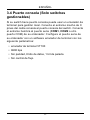
4 Solución de problemas
PROBLEMA ACCIÓN
Ningún LED
está activo y el
cable de
alimentación
está conectado.
Verifique que el cable de alimentación o
cable adaptador de alimentación está
conectado al conector de alimentación del
switch y a la toma de alimentación
adecuada. Si el error persiste seguramente
debe tener un problema de hardware,
contacte con su distribuidor.
El LED LNK/
ACT no se
enciende y no
parpadea
cuando el
switch está
encendido.
Verifique que los dispositivos conectados
estén encendidos y correctamente
conectados a su switch. También asegúrese
de que las tarjetas Ethernet de los
dispositivos conectados funcionan
correctamente. Verifique que los cables de
red no superan los 100 metros.
La page est en cours de chargement...
La page est en cours de chargement...
La page est en cours de chargement...
La page est en cours de chargement...
La page est en cours de chargement...
La page est en cours de chargement...
La page est en cours de chargement...
La page est en cours de chargement...
La page est en cours de chargement...
La page est en cours de chargement...
La page est en cours de chargement...
La page est en cours de chargement...
La page est en cours de chargement...
La page est en cours de chargement...
La page est en cours de chargement...
La page est en cours de chargement...
La page est en cours de chargement...
La page est en cours de chargement...
La page est en cours de chargement...
La page est en cours de chargement...
La page est en cours de chargement...
La page est en cours de chargement...
La page est en cours de chargement...
La page est en cours de chargement...
-
 1
1
-
 2
2
-
 3
3
-
 4
4
-
 5
5
-
 6
6
-
 7
7
-
 8
8
-
 9
9
-
 10
10
-
 11
11
-
 12
12
-
 13
13
-
 14
14
-
 15
15
-
 16
16
-
 17
17
-
 18
18
-
 19
19
-
 20
20
-
 21
21
-
 22
22
-
 23
23
-
 24
24
-
 25
25
-
 26
26
-
 27
27
-
 28
28
-
 29
29
-
 30
30
-
 31
31
-
 32
32
-
 33
33
-
 34
34
-
 35
35
-
 36
36
-
 37
37
-
 38
38
-
 39
39
-
 40
40
-
 41
41
-
 42
42
-
 43
43
-
 44
44


ZyXEL XGS3600-26F Guide de démarrage rapide
- Catégorie
- Commutateurs réseau
- Taper
- Guide de démarrage rapide
- Ce manuel convient également à
dans d''autres langues
- italiano: ZyXEL XGS3600-26F Guida Rapida
- español: ZyXEL XGS3600-26F Guía de inicio rápido
- Deutsch: ZyXEL XGS3600-26F Schnellstartanleitung


