Lincoln Electric AutoDrive 4R100 Mode d'emploi
- Catégorie
- Système de soudage
- Taper
- Mode d'emploi

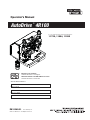
Operator’s Manual
AutoDrive
®
4R100
Register your machine:
www.lincolnelectric.com/register
Authorized Service and Distributor Locator:
www.lincolnelectric.com/locator
IM10069-B | Issue D ate Apr-13
© Lincoln Global, Inc. All Rights Reserved.
For use with machines having Code Numbers:
11729, 11884, 11955
Save for future reference
Date Purchased
Code: (ex: 10859)
Serial: (ex: U1060512345)

THANK YOU FOR SELECTING
A QUALITY PRODUCT BY
LINCOLN ELEC TRIC.
PLEASE EXAMINE CARTON AND EQUIPMENT FOR
DAMAGE IMMEDIATELY
When this equipment is shipped, title passes to the purchaser
upon receipt by the carrier. Consequently, claims for material
damaged in shipment must be made by the purchaser against the
transportation company at the time the shipment is received.
SAFETY DEPENDS ON YOU
Lincoln arc welding and cutting equipment is designed and built
with safety in mind. However, your overall safety can be increased
by proper installation ... and thoughtful operation on your part.
DO NOT INSTALL, OPERATE OR REPAIR THIS EQUIPMENT
WITHOUT READING THIS MANUAL AND THE SAFETY
PRECAUTIONS CONTAINED THROUGHOUT. And, most importantly,
think before you act and be careful.
This statement appears where the information must be followed
exactly to avoid serious personal injury or loss of life.
This statement appears where the information must be followed
to avoid minor personal injury or damage to this equipment.
KEEP YOUR HEAD OUT OF THE FUMES.
DON’T get too close to the arc.
Use corrective lenses if necessary
to stay a reasonable distance
away from the arc.
READ and obey the Safety Data
Sheet (SDS) and the warning label
that appears on all containers of
welding materials.
USE ENOUGH VENTILATION or
exhaust at the arc, or both, to
keep the fumes and gases from
your breathing zone and the general area.
IN A LARGE ROOM OR OUTDOORS, natural ventilation may be
adequate if you keep your head out of the fumes (See below).
USE NATURAL DRAFTS or fans to keep the fumes away
from your face.
If you de velop unusual symptoms, see your supervisor.
Perhaps the welding atmosphere and ventilation system
should be checked.
WEAR CORRECT EYE, EAR &
BODY PROTECTION
PROTECT your eyes and face with welding helmet
properly fitted and with proper grade of filter plate
(See ANSI Z49.1).
PROTECT your body from welding spatter and arc
flash with protective clothing including woolen
clothing, flame-proof apron and gloves, leather
leggings, and high boots.
PROTECT others from splatter, flash, and glare
with protective screens or barriers.
IN SOME AREAS, protection from noise may be appropriate.
BE SURE protective equipment is in good condition.
Also, wear safety glasses in work area
AT ALL TIMES.
SPECIAL SITUATIONS
DO NOT WELD OR CUT containers or materials which previously
had been in contact with hazardous substances unless they are
properly cleaned. This is extremely dangerous.
DO NOT WELD OR CUT painted or plated parts unless special
precautions with ventilation have been taken. They can release
highly toxic fumes or gases.
Additional precautionary measures
PROTECT compressed gas cylinders from excessive heat,
mechanical shocks, and arcs; fasten cylinders so they cannot fall.
BE SURE cylinders are never grounded or part of an
electrical circuit.
REMOVE all potential fire hazards from welding area.
ALWAYS HAVE FIRE FIGHTING EQUIPMENT READY FOR
IMMEDIATE USE AND KNOW HOW TO USE IT.
WARNING
CAUTION
Safety 01 of 04 - 5/16/2018

SECTION A:
WARNINGS
CALIFORNIA PROPOSITION 65 WARNINGS
WARNING: Breathing diesel engine exhaust
exposes you to chemicals known to the State
of California to cause cancer and birth defects,
or other reproductive harm.
• Always start and operate the engine in a
well-ventilated area.
• If in an exposed area, vent the exhaust to the outside.
• Do not modify or tamper with the exhaust system.
• Do not idle the engine except as necessary.
For more information go to
www.P65 warnings.ca.gov/diesel
WARNING: This product, when used for welding or
cutting, produces fumes or gases which contain
chemicals known to the State of California to cause
birth defects and, in some cases, cancer. (California
Health & Safety Code § 25249.5 et seq.)
WARNING: Cancer and Reproductive Harm
www.P65warnings.ca.gov
ARC WELDING CAN BE HAZARDOUS. PROTECT
YOURSELF AND OTHERS FROM POSSIBLE SERIOUS
INJURY OR DEATH. KEEP CHILDREN AWAY.
PACEMAKER WEARERS SHOULD CONSULT WITH
THEIR DOCTOR BEFORE OPERATING.
Read and understand the following safety highlights. For
additional safety information, it is strongly recommended
that you purchase a copy of “Safety in Welding & Cutting -
ANSI Standard Z49.1” from the American Welding Society,
P.O. Box 351040, Miami, Florida 33135 or CSA Standard
W117.2-1974. A Free copy of “Arc Welding Safety” booklet
E205 is available from the Lincoln Electric Company,
22801 St. Clair Avenue, Cleveland, Ohio 44117-1199.
BE SURE THAT ALL INSTALLATION, OPERATION,
MAINTENANCE AND REPAIR PROCEDURES ARE
PERFORMED ONLY BY QUALIFIED INDIVIDUALS.
FOR ENGINE POWERED
EQUIPMENT.
1.a. Turn the engine off before troubleshooting
and maintenance work unless the
maintenance work requires it to be running.
1.b. Operate engines in open, well-ventilated areas or vent the engine
exhaust fumes outdoors.
1.c. Do not add the fuel near an open flame welding
arc or when the engine is running. Stop the
engine and allow it to cool before refueling to
prevent spilled fuel from vaporizing on contact
with hot engine parts and igniting. Do not spill fuel when filling
tank. If fuel is spilled, wipe it up and do not start engine until
fumes have been eliminated.
1.d. Keep all equipment safety guards, covers
and devices in position and in good repair.
Keep hands, hair, clothing and tools away
from V-belts, gears, fans and all other
moving parts when starting, operating or
repairing equipment.
1.e. In some cases it may be necessary to remove safety guards to
perform required maintenance. Remove guards only when
necessary and replace them when the maintenance requiring
their removal is complete. Always use the greatest care when
working near moving parts.
1.f. Do not put your hands near the engine fan. Do not attempt to
override the governor or idler by pushing on the throttle control
rods while the engine is running.
1.g. To prevent accidentally starting gasoline engines while turning
the engine or welding generator during maintenance work,
disconnect the spark plug wires, distributor cap or magneto wire
as appropriate.
1.h. To avoid scalding, do not remove the radiator
pressure cap when the engine is
hot.
ELECTRIC AND
MAGNETIC FIELDS MAY
BE DANGEROUS
2.a. Electric current flowing through any conductor
causes localized Electric and Magnetic Fields (EMF).
Welding current creates EMF fields around welding cables
and welding machines
2.b. EMF fields may interfere with some pacemakers, and
welders having a pacemaker should consult their physician
before welding.
2.c. Exposure to EMF fields in welding may have other health effects
which are now not known.
2.d. All welders should use the following procedures in order to
minimize exposure to EMF fields from the welding circuit:
2.d.1. Route the electrode and work cables together - Secure
them with tape when possible.
2.d.2. Never coil the electrode lead around your body.
2.d.3. Do not place your body between the electrode and work
cables. If the electrode cable is on your right side, the
work cable should also be on your right side.
2.d.4. Connect the work cable to the workpiece as close as pos-
sible to the area being welded.
2.d.5. Do not work next to welding power source.
SAFETY
Safety 02 of 04 - 5/16/2018

ELECTRIC SHOCK
CAN KILL.
3.a. The electrode and work (or ground) circuits are
electrically “hot” when the welder is on. Do
not touch these “hot” parts with your bare skin or wet clothing.
Wear dry, hole-free gloves to insulate hands.
3.b. Insulate yourself from work and ground using dry insulation.
Make certain the insulation is large enough to cover your full area
of physical contact with work and ground.
In addition to the normal safety precautions, if
welding must be performed under electrically
hazardous conditions (in damp locations or while
wearing wet clothing; on metal structures such as
floors, gratings or scaffolds; when in cramped
positions such as sitting, kneeling or lying, if there
is a high risk of unavoidable or accidental contact
with the workpiece or ground) use the following
equipment:
• Semiautomatic DC Constant Voltage (Wire) Welder.
• DC Manual (Stick) Welder.
• AC Welder with Reduced Voltage Control.
3.c. In semiautomatic or automatic wire welding, the electrode,
electrode reel, welding head, nozzle or semiautomatic welding
gun are also electrically “hot”.
3.d. Always be sure the work cable makes a good electrical
connection with the metal being welded. The connection should
be as close as possible to the area being welded.
3.e. Ground the work or metal to be welded to a good electrical (earth)
ground.
3.f. Maintain the electrode holder, work clamp, welding cable and
welding machine in good, safe operating condition. Replace
damaged insulation.
3.g. Never dip the electrode in water for cooling.
3.h. Never simultaneously touch electrically “hot” parts of electrode
holders connected to two welders because voltage
between the
two can be the total of the open circuit voltage of both
welders.
3.i. When working above floor level, use a safety belt to protect
yourself from a fall should you get a shock.
3.j. Also see It ems 6.c. and 8.
ARC RAYS CAN BURN.
4.a. Use a shield with the proper filter and cover plates to protect your
eyes from sparks and the rays of the arc when welding or
observing open arc welding. Headshield and filter lens should
conform to ANSI Z87. I standards.
4.b. Use suitable clothing made from durable flame-resistant material
to protect your skin and that of your helpers from the arc rays.
4.c. Protect other nearby personnel with suitable, non-flammable
screening and/or warn them not to watch the arc nor expose
themselves to the arc rays or to hot spatter or metal.
FUMES AND GASES
CAN BE DANGEROUS.
5.a. Welding may produce fumes and gases
hazardous to health. Avoid breathing these
fumes and gases. When welding, keep your head out of the fume.
Use enough ventilation and/or exhaust at the arc to keep fumes
and gases away from the breathing zone. When welding
hardfacing (see instructions on container or SDS)
or on lead or cadmium plated steel and other
metals or coatings which produce highly toxic
fumes, keep exposure as low as possible and
within applicable OSHA PEL and ACGIH TLV limits
using local exhaust or mechanical ventilation
unless exposure assessments indicate otherwise.
In confined spaces or in some circumstances,
outdoors, a respirator may also be required.
Additional precautions are also required when
welding
on galvanized steel.
5. b. The operation of welding fume control equipment is affected by
various factors including proper use and positioning of the
equipment, maintenance of the equipment and the specific
welding procedure and application involved. Worker exposure
level should be checked upon installation and periodically
thereafter to be certain it is within applicable OSHA PEL and
ACGIH TLV limits.
5.c. Do not weld in locations near chlorinated hydrocarbon vapors
coming from degreasing, cleaning or spraying operations. The
heat and rays of the arc can react with solvent vapors to form
phosgene, a highly toxic gas, and other irritating products.
5.d. Shielding gases used for arc welding can displace air and
cause
injury or death. Always use enough ventilation, especially in
confined areas, to insure breathing air is safe.
5.e. Read and understand the manufacturer’s instructions for this
equipment and the consumables to be used, including the
Safety Data Sheet (SDS) and follow your employer’s safety
practices. SDS forms are available from your welding
distributor or from the manufacturer.
5.f. Also see item 1.b.
SAFETY
Safety 03 of 04 - 5/16/2018

WELDING AND CUTTING
SPARKS CAN CAUSE
FIRE OR EXPLOSION.
6.a. Remove fire hazards from the welding area. If
this is not possible, cover them to prevent the welding sparks
from starting a fire. Remember that welding sparks and hot
materials from welding can easily go through small cracks and
openings to adjacent areas. Avoid welding near hydraulic lines.
Have a fire extinguisher readily available.
6.b. Where compressed gases are to be used at the job site, special
precautions should be used to prevent hazardous situations.
Refer to “Safety in Welding and Cutting” (ANSI Standard Z49.1)
and the operating information for the equipment being used.
6.c. When not welding, make certain no part of the electrode circuit is
touching the work or ground. Accidental contact can cause
overheating and create a fire hazard.
6.d. Do not heat, cut or weld tanks, drums or containers until the
proper steps have been taken to insure that such procedures
will not cause flammable or toxic vapors from substances inside.
They can cause an explosion even though they have been
“cleaned”. For information, purchase “Recommended Safe
Practices for the Preparation for Welding and Cutting of
Containers and Piping That Have Held Hazardous Substances”,
AWS F4.1 from the American Welding Society
(see address above).
6.e. Vent hollow castings or containers before heating, cutting or
welding. They may explode.
6.f. Sparks and spatter are thrown from the welding arc. Wear oil free
protective garments such as leather gloves, heavy shirt, cuffless
trousers, high shoes and a cap over your hair. Wear ear plugs
when welding out of position or in confined places. Always wear
safety glasses with side shields when in a welding area.
6.g. Connect the work cable to the work as close to the welding area
as practical. Work cables connected to the building framework or
other locations away from the welding area increase the
possibility of the welding current passing through lifting chains,
crane cables or other alternate circuits. This can create fire
hazards or overheat lifting chains or cables until they fail.
6.h. Also see item 1.c.
6.I. Read and follow NFPA 51B “Standard for Fire Prevention During
Welding, Cutting and Other Hot Work”, available from NFPA, 1
Batterymarch Park, PO box 9101, Quincy, MA 022690-9101.
6.j. Do not use a welding power source for pipe thawing.
CYLINDER MAY EXPLODE IF
DAMAGED.
7.a. Use only compressed gas cylinders containing
the correct shielding gas for the process used
and properly operating regulators designed for
the gas and pressure used. All hoses, fittings,
etc. should be suitable for the application and
maintained in good condition.
7.b. Always keep cylinders in an upright position securely chained to
an undercarriage or fixed support.
7.c. Cylinders should be located:
• Away from areas where they may be struck or subjected
to physical damage.
• A safe distance from arc welding or cutting operations
and any other source of heat, sparks, or flame.
7.d. Never allow the electrode, electrode holder or any other
electrically “hot” parts to touch a cylinder.
7.e. Keep your head and face away from the cylinder valve outlet
when opening the cylinder valve.
7.f. Valve protection caps should always be in place and hand tight
except when the cylinder is in use or connected for use.
7.g. Read and follow the instructions on compressed gas cylinders,
associated equipment, and CGA publication P-l, “Precautions for
Safe Handling of Compressed Gases in Cylinders,” available from
the Compressed Gas Association, 14501 George Carter Way
Chantilly, VA 20151.
FOR ELECTRICALLY
POWERED EQUIPMENT.
8.a. Turn off input power using the disconnect
switch at the fuse box before working on
the equipment.
8.b. Install equipment in accordance with the U.S. National Electrical
Code, all local codes and the manufacturer’s recommendations.
8.c. Ground the equipment in accordance with the U.S. National
Electrical Code and the manufacturer’s recommendations.
Refer to
http://www.lincolnelectric.com/safety
for additional safety information.
SAFETY
Safety 04 of 04 - 5/16/2018

iv
SAFETY
iv
PRÉCAUTIONS DE SÛRETÉ
Pour votre propre protection lire et observer toutes les instructions
et les précautions de sûreté specifiques qui parraissent dans ce
manuel aussi bien que les précautions de sûreté générales suiv-
antes:
Sûreté Pour Soudage A LʼArc
1. Protegez-vous contre la secousse électrique:
a. Les circuits à lʼélectrode et à la piéce sont sous tension
quand la machine à souder est en marche. Eviter toujours
tout contact entre les parties sous tension et la peau nue
ou les vétements mouillés. Porter des gants secs et sans
trous pour isoler les mains.
b. Faire trés attention de bien sʼisoler de la masse quand on
soude dans des endroits humides, ou sur un plancher
metallique ou des grilles metalliques, principalement dans
les positions assis ou couché pour lesquelles une grande
partie du corps peut être en contact avec la masse.
c. Maintenir le porte-électrode, la pince de masse, le câble
de soudage et la machine à souder en bon et sûr état
defonctionnement.
d.Ne jamais plonger le porte-électrode dans lʼeau pour le
refroidir.
e. Ne jamais toucher simultanément les parties sous tension
des porte-électrodes connectés à deux machines à souder
parce que la tension entre les deux pinces peut être le
total de la tension à vide des deux machines.
f. Si on utilise la machine à souder comme une source de
courant pour soudage semi-automatique, ces precautions
pour le porte-électrode sʼapplicuent aussi au pistolet de
soudage.
2. Dans le cas de travail au dessus du niveau du sol, se protéger
contre les chutes dans le cas ou on recoit un choc. Ne jamais
enrouler le câble-électrode autour de nʼimporte quelle partie
du corps.
3. Un coup dʼarc peut être plus sévère quʼun coup de soliel,
donc:
a. Utiliser un bon masque avec un verre filtrant approprié
ainsi quʼun verre blanc afin de se protéger les yeux du ray-
onnement de lʼarc et des projections quand on soude ou
quand on regarde lʼarc.
b. Porter des vêtements convenables afin de protéger la
peau de soudeur et des aides contre le rayonnement de
lʻarc.
c. Protéger lʼautre personnel travaillant à proximité au
soudage à lʼaide dʼécrans appropriés et non-inflammables.
4. Des gouttes de laitier en fusion sont émises de lʼarc de
soudage. Se protéger avec des vêtements de protection libres
de lʼhuile, tels que les gants en cuir, chemise épaisse, pan-
talons sans revers, et chaussures montantes.
5. Toujours porter des lunettes de sécurité dans la zone de
soudage. Utiliser des lunettes avec écrans lateraux dans les
zones où lʼon pique le laitier.
6. Eloigner les matériaux inflammables ou les recouvrir afin de
prévenir tout risque dʼincendie dû aux étincelles.
7. Quand on ne soude pas, poser la pince à une endroit isolé de
la masse. Un court-circuit accidental peut provoquer un
échauffement et un risque dʼincendie.
8. Sʼassurer que la masse est connectée le plus prés possible
de la zone de travail quʼil est pratique de le faire. Si on place
la masse sur la charpente de la construction ou dʼautres
endroits éloignés de la zone de travail, on augmente le risque
de voir passer le courant de soudage par les chaines de lev-
age, câbles de grue, ou autres circuits. Cela peut provoquer
des risques dʼincendie ou dʼechauffement des chaines et des
câbles jusquʼà ce quʼils se rompent.
9. Assurer une ventilation suffisante dans la zone de soudage.
Ceci est particuliérement important pour le soudage de tôles
galvanisées plombées, ou cadmiées ou tout autre métal qui
produit des fumeés toxiques.
10. Ne pas souder en présence de vapeurs de chlore provenant
dʼopérations de dégraissage, nettoyage ou pistolage. La
chaleur ou les rayons de lʼarc peuvent réagir avec les vapeurs
du solvant pour produire du phosgéne (gas fortement toxique)
ou autres produits irritants.
11. Pour obtenir de plus amples renseignements sur la sûreté,
voir le code “Code for safety in welding and cutting” CSA
Standard W 117.2-1974.
PRÉCAUTIONS DE SÛRETÉ POUR
LES MACHINES À SOUDER À
TRANSFORMATEUR ET À
REDRESSEUR
1. Relier à la terre le chassis du poste conformement au code de
lʼélectricité et aux recommendations du fabricant. Le dispositif
de montage ou la piece à souder doit être branché à une
bonne mise à la terre.
2. Autant que possible, Iʼinstallation et lʼentretien du poste seront
effectués par un électricien qualifié.
3. Avant de faires des travaux à lʼinterieur de poste, la debranch-
er à lʼinterrupteur à la boite de fusibles.
4. Garder tous les couvercles et dispositifs de sûreté à leur
place.

vi
vi
TABLE OF CONTENTS
Page
––––––––––––––––––––––––––––––––––––––––––––––––––––––––––––––––––––––––––––––––
Installation.......................................................................................................................Section A
Technical Specifications.......................................................................................................A-1
Safety Precautions ...............................................................................................................A-2
Location................................................................................................................................A-2
Weld Cable Sizes .................................................................................................................A-2
Coaxial Weld Cable..............................................................................................................A-3
Wire Drive Cable .................................................................................................................A-4
Shielding Gas Connection....................................................................................................A-5
Procedure to Install Drive Rolls and Wire Guides ................................................................A-6
Pressure Arm Adjustment, Conduit Installation....................................................................A-7
System Set-Up .....................................................................................................................A-8
________________________________________________________________________________
Operation.........................................................................................................................Section B
Safety Precautions ...............................................................................................................B-1
Graphic Symbols that appear on this Machine or in this Manual .........................................B-1
Definition of Welding Terms .................................................................................................B-2
Product Description ..............................................................................................................B-2
Recommended Processes, Equipment Limitations, Recommended Power Sources ..........B-2
________________________________________________________________________________
Accessories ....................................................................................................................Section C
Optinal Kits and Accessories ...............................................................................................C-1
Drive Roll Kits used..............................................................................................................C-1
Accessories Used.........................................................................................................C-2, C-3
________________________________________________________________________________
Maintenance....................................................................................................................Section D
Safety Precautions ...............................................................................................................D-1
Routine Maintenance ...........................................................................................................D-1
________________________________________________________________________________
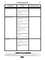
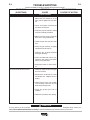
Troubleshooting .............................................................................................................Section E
How to Use Troubleshooting Guide .....................................................................................E-1
Troubleshooting Guide .................................................................................................E-2, E-3
________________________________________________________________________________
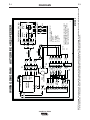
Wiring Diagram & Dimension Prints .............................................................................Section F
________________________________________________________________________________
Parts Pages ................................................................................................................P-658 Series
_______________________________________________________________________
________

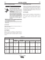
DUTY CYCLE
• The duty cycle is based upon the amount of welding performed in a 10 minute period.
• Thermal test have been performed at ambient temperature. The duty cycle (duty factory) @ 40°C (104ºF) has
been determined by simulation .
A-1
INSTALLATION
A-1
AutoDrive
®
4R100
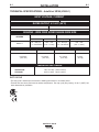
TECHNICAL SPECIFICATIONS –
AutoDrive
®
4R100 (K3002-1)
TEMPERATURE RANGE
OPERATION: -40°F to 104°F (-40°C to 40°C)
STORAGE: -40°F to 185°F (-40°C to 85°C)
INPUT VOLTAGE, CURRENT
HEIGHT WIDTH LENGTH WEIGHT
8.4 Inches 7.5 Inches 9.1 Inches 13.2 lbs
(213 mm) ( 191 mm) (231 mm) (6.0 kg)
PHYSICAL DIMENSIONS
INPUT VOLTAGE ± 10%
0-40 VDC
INPUT AMPERES
4A
RATED OUTPUT @ 104°F (40°C)
DUTY CYCLE
100% rating
INPUT AMPERES
500
GEARING - WIRE FEED SPEED RANGE-WIRE SIZE
WFS RANGE
50 – 800 ipm
(1.3 – 20.3m/min)
WFS RANGE
50 – 800 ipm
(1.3 – 20.3m/min)
WIRE SIZES
.023 – .045"
(0.6 – 1.2mm)
WIRE SIZES
.035 - .045”
(0.9 – 1.2mm)
GEARING
K3002-1
GMAW
FCAW

LOCATION
Firmly secure the AutoDrive
®
4R100 wire feeder to a
robot arm or fixture.
Mount only in a dry environment.
SOFTWARE:
When the feeder is installed in a Power Wave
®
or
Robotic system, select “AutoDrive
®
4R100” from the
list of feeders. Refer to the Power Wave
®
or Robotic
manual.
** Tabled values are for operation at ambient temperatures of 104°F(40°C) and below. Applications above 104°F(40°C) may require cables
larger than recommended, or cables rated higher than 167°F(75°C).
RECOMMENDED CABLE SIZES (RUBBER COVERED COPPER - RATED 167°F or 75°C)**
CABLE SIZES FOR COMBINED LENGTHS OF ELECTRODE AND WORK CABLES
AMPERES
200
200
225
225
250
250
250
250
300
325
350
400
400
500
PERCENT
DUTY
CYCLE
60
100
20
40 & 30
30
40
60
100
60
100
60
60
100
60
0 to 50Ft.
(0 to15m)
2
2
4 or 5
3
3
2
1
1
1
2/0
1/0
2/0
3/0
2/0
50 to 100Ft.
(15 to 30m)
2
2
3
3
3
2
1
1
1
2/0
1/0
2/0
3/0
2/0
100 to 150 Ft.
(30 to 46m)
2
2
2
2
2
1
1
1
1
2/0
2/0
2/0
3/0
3/0
150 to 200 Ft.
(46 to 61m)
1
1
1
1
1
1
1
1
1/0
2/0
2/0
3/0
3/0
3/0
200 to 250 Ft.
(61 to 76m)
1/0
1/0
1/0
1/0
1/0
1/0
1/0
1/0
2/0
3/0
3/0
4/0
4/0
4/0
TABLE A.1
A-2
INSTALLATION
AutoDrive
®
4R100
A-2
SAFETY PRECAUTIONS
ELECTRIC SHOCK CAN KILL.
• Turn the input power OFF at the
welding power source before
installation or changing drive rolls
and/or guides.
• Do not touch electrically live parts.
• When inching with the gun trigger,
electrode and drive mechanism are
"hot" to work and ground and
could remain energized several
seconds after the gun trigger is
released.
• Welding power source must be connected to
system ground per the National Electrical Code
or any applicable local codes.
• Only qualified personnel should perform mainte-
nance work.
----------------------------------------------------------------------
WELD CABLE SIZE
Table A.1 located below are copper cable sizes rec-
ommended for different currents and duty cycles.
Lengths stipulated are the distance from the welder to
work and back to the welder again. Cable sizes are
increased for greater lengths primarily for the purpose
of minimizing cable drop.
SOFTWARE:
When the feeder is installed in a Power Wave
®
or
Robotic system, select “AutoDrive
®
4R100” from the
list of feeders. Refer to the Power Wave
®
or Robotic
manual.
WARNING

A-3
INSTALLATION
AutoDrive
®
4R100
A-3
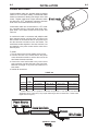
COAXIAL WELD CABLE
Coaxial welding cables are specially designed welding
cables for STT
®
and pulse welding. Coaxial weld cables
feature low inductance, allowing fast changes in the weld
current. Regular cables have a higher inductance which
may distort the STT
®
waveshape. Inductance becomes
more severe as the weld cables become longer.
Coaxial weld cables are recommended for STT
®
weld-
ing, especially when the total weld cable length (elec-
trode cable + work cable) exceeds 50 feet (7.6m). See
Table A.2.
A coaxial weld cable is constructed with multiple small
leads wrapped around one large lead. The large inner
lead connects to the electrode stud on the power source
and the electrode connection on the wire feeder. The
small leads combine together to form the work lead, one
end attached to the power source and the other end to
the work piece.
To install:
1. Turn the input power off at the welding power source.
2. Connect one end of the center lead to the power
source electrode connection, and the other end to the
wire feeder electrode connection.
3. Connect the outer lead bundle to the power source
work connection, and the other end to the work piece.
Minimize the length of any work lead extension for
best results.
4. Insulate all connections.
El ec t r ode
El ec t r ode
W
or k
or k
Amperes
250
300
350
Duty
Cycle
100%
60%
60%
0 to 25 Ft.
1
1
1/0
25 to 50 Ft.
1
1
1/0
50 to 75 Ft.
1
1
--
75 to 100 Ft.
1
1/0
--
COAXIAL CABLE LENGTH
RECOMMENDED CABLE SIZES (RUBBER COVERED COPPER - RATED 75°C)**
Electrode
Electrode
Work
Work
Electrode
Electrode
Work
Work
Power Source
Power Source
Coaxial Weld Cable
Coaxial Weld Cable
Wire Feeder
Wire Feeder
TABLE A.2
** Tabled values are for operation at ambient temperatures of 104°F(40°C) and below.
Applications above 104°F(40°C) may require cables larger than recommended, or cables rated
higher than 167°F(75°C).

A-4
INSTALLATION
AutoDrive
®
4R100
A-4
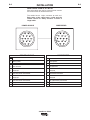
A
B
K
H
N
L
C
D
M
G
F
E
J
I
POWER SOURCE
WIRE FEEDER
A
B
K
H
N
L
C
D
M
G
F
E
J
I
Function
Motor Power
Motor Power
Gas Solenoid
Gas Solenoid
Reserved
Reserved
“2A” Differential Tachometer
“2B” Differential Tachometer
Reserved
Reserved
“1A” Differential Tachometer
“1B” Differential Tachometer
Reserved
“67” Electrode Sense Lead
Pin
A
B
C
D
E
F
G
H
I
J
K
L
M
N
WIRE DRIVE CABLE, K1785-XX
Wire drive cables are used to connect power sources
and control boxes to remote wire drives.
The cables have a 14-pin connector at each end.
Both ends of the cable have a collar and the
cables cannot be “daisy chained” to make a
longer cable.
Function
Motor Power
Motor Power
Gas Solenoid
Gas Solenoid
“2A” Differential Tachometer
Reserved
+15VDC Tech Supply
Tachometer Common
Reserved
Reserved
“1A” Differential Tachometer
“1B” Differential Tachometer
“2B” Differential Tachometer
“67” Electrode Sense Lead
Pin
A
B
C
D
E
F
G
H
I
J
K
L
M
N
POWER SOURCE
WIRE FEEDER

A-5
INSTALLATION
AutoDrive
®
4R100
A-5
SHIELDING GAS CONNECTION
CYLINDER may explode if
damaged.
• Keep cylinder upright and
chained to support.
• Keep cylinder away from areas where it may be
damaged.
• Never lift welder with cylinder attached.
• Never allow welding electrode to touch cylinder.
• Keep cylinder away from welding or other live
electrical circuits.
• BUILD UP OF SHIELDING GAS MAY
HARM HEALTH OR KILL.
• Shut off shielding gas supply when not
in use.
• See American National Standard Z-49.1, "Safety
in Welding and Cutting” Published by the
American Welding Society.
----------------------------------------------------------------------
Maximum inlet pressure is 100 psi. (6.9 bar.)
Install the shielding gas supply as follows:
1. Secure the cylinder to prevent it from falling.
2. Remove the cylinder cap. Inspect the cylinder valves
and regulator for damaged threads, dirt, dust, oil or
grease. Remove dust and dirt with a clean cloth. DO
NOT ATTACH THE REGULATOR IF OIL, GREASE
OR DAMAGE IS PRESENT! Inform your gas supplier
of this condition. Oil or grease in the presence of high
pressure oxygen is explosive.
3. Stand to one side away from the outlet and open the
cylinder valve for an instant. This blows away any dust
or dirt which may have accumulated in the valve out-
let.
4. Attach the flow regulator to the cylinder valve and
tighten the union nut(s) securely with a wrench. Note:
if connecting to 100% CO
2
cylinder, insert regulator
adapter between regulator and cylinder valve. If
adapter is equipped with a plastic washer, be sure it is
seated for connection to the CO
2
cylinder.
WARNING
5. Attach one end of the inlet hose to the outlet fitting of
the flow regulator. Attach the other end to the welding
system shielding gas inlet. Tighten the union nuts with
a wrench.
6. Before opening the cylinder valve, turn the regulator
adjusting knob counterclockwise until the adjusting
spring pressure is released.
7. Standing to one side, open the cylinder valve slowly a
fraction of a turn. When the cylinder pressure gage
stops moving, open the valve fully.
8. The flow regulator is adjustable. Adjust it to the flow
rate recommended for the procedure and process
being used before making a weld.

A-6
INSTALLATION
AutoDrive
®
4R100
A-6
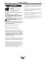
PROCEDURE TO INSTALL DRIVE ROLLS
AND WIRE GUIDES
ELECTRIC SHOCK can kill.
• Turn the input power OFF at the weld-
ing power source before installation
or changing drive rolls and/or guides.
• Do not touch electrically live parts.
• When inching with the gun trigger, electrode and
drive mechanism are "hot" to work and ground
and could remain energized several seconds
after the gun trigger is released.
• Do not operate with covers, panels or guards
removed or open.
• Only qualified personnel should perform mainte-
nance work.
----------------------------------------------------------------------
To remove drive rolls and wire guides:
1. Turn power off at the welding power source.
2. Remove the outer wire guide.
3.
Rotate all of the triangular rings to the unlocked
position.
WARNING
4. Open the idle arms.
5. Remove the drive rolls and inner wire guide.
To install drive rolls and wire guides:
1. Turn off power at the welding power source.
2. Open the idle arms.
3. Assemble the inner wire guide.
4. Slide the drive rolls onto the drive hubs.
5. Close the idle arms.
6. Rotate all of the triangular rings to the locked posi-
tion.
7. Assemble the outer wire guide.
8. Adjust the pressure arms to the recommended
setting.
INNER WIRE GUIDE
IDLER ARM OPENED
DRIVE ROLLS
OUTER WIRE GUIDE

A-7
INSTALLATION
AutoDrive
®
4R100
A-7
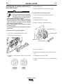
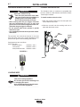
CONDUIT INSTALLATION
The K1546-xx series of conduits are compatible with
K515-xx, K565-xx, Wire Wizard and Electron Beam
Technologies conduits.
To install conduit to the wire drive:
1. Slide the conduit bushing into the feed plate and
secure with the set screw.
2. Slide the conduit into the bushing and lock in
place with the thumb screw.
CONDUIT
CONDUIT
BUSHING
THUMB
SCREW
SET
SCREW
PRESSURE ARM ADJUSTMENT
ELECTRIC SHOCK can kill.
• Turn the input power OFF at the weld-
ing power source before installation or
changing drive rolls and/or guides.
• Do not touch electrically live parts.
• When inching with the gun trigger, electrode
and drive mechanism are "hot" to work and
ground and could remain energized several sec-
onds after the gun trigger is released.
• Do not operate with covers, panels or guards
removed or open.
• Only qualified personnel should perform mainte-
nance work.
------------------------------------------------------------------------
The pressure arm controls the amount of force the
drive rolls exert on the wire. Proper adjustment of the
pressure arm gives the best welding performance.
Set the pressure arm as follows:
(See Figure A.3)
Aluminum wires between 1 and 3
Cored wires between 3 and 4
Steel, Stainless wires
between 4 and 6
LOADING WIRE
• Keep hands, hair, clothing and tools
away from rotating equipment.
• Do not wear gloves when threading wire
or changing wire spool.
• Only qualified personnel should install,
use or service this equipment.
------------------------------------------------------------------------
WARNING
WARNING
FIGURE A.3

A-8
INSTALLATION
AutoDrive
®
4R100
A-8
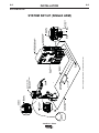
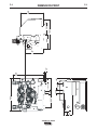
SYSTEM SET-UP
ArcLink XT
Connection
ArcLink
(5 Pin)
Work
Sense
Wire Feeder
(14 Pin)
Robotic
Torch
Power Wave® i400
K2669-1
Work Piece
FANUC R-J30iA Controller
with Integrated Op Box
Optional Work
Sense Lead (21)
K1785-XX Wire Feeder
K884-5,-6
Control Cable
* Work
Cable (-)
Internal ArcLink XT
Communication
* Electrode
Cable (+)
SYSTEM SET-UP (SINGLE ARM)
Wire Feeder
(14 Pin)
Gas
Air
AutoDrive® 4R100
(Without Cover Shown)
ArcMate 100iC
* Refer to "Output Cable Guidelines" for recommended cable size
Electrode
K1505-XX
K1507-XX
Connection

B-1
OPERATION
AutoDrive
®
4R100
B-1
• ELECTRIC SHOCK CAN KILL.
Unless using COLD FEED fea-
ture, when feeding with gun trig-
ger, the electrode and drive
mechanism are always electri-
cally energized and could
remain energized several sec-
onds after the welding ceases..
• Do not touch electrically live part or electrode
with skin or wet clothing.
• Insulate yourself from work and ground.
• Always wear dry insulating gloves.
• Do not operate with covers, panels or guards
removed or open.
----------------------------------------------------------------------
• FUMES AND GASSES can be
dangerous.
• Keep your head out of fumes.
•
Use ventilation or exhaust to
remove fumes from breathing
zone.
----------------------------------------------------------------------
• WELDING SPARKS can cause
fire or explosion.
• Keep flammable material away.
----------------------------------------------------------------------
ARC RAYS can burn.
• Wear eye, ear and body protec-
tion.
----------------------------------------------------------------------
SEE ADDITIONAL WARNING INFORMATION
UNDER ARC WELDING SAFETY PRECAUTIONS
AND IN THE FRONT OF THIS OPERATING MAN-
UAL.
----------------------------------------------------------------------
WARNING
SAFETY PRECAUTIONS
READ AND UNDERSTAND ENTIRE SECTION
BEFORE OPERATING MACHINE.
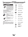
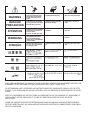
WIRE FEEDER
POSITIVE OUTPUT
NEGATIVE OUTPUT
INPUT POWER
DIRECT CURRENT
OPEN CIRCUIT
VOLTAGE
INPUT VOLTAGE
OUTPUT VOLTAGE
INPUT CURRENT
OUTPUT CURRENT
PROTECTIVE
GROUND
WARNING OR
CAUTION
U
0
U
1
U
2
I
1
I
2
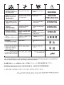
GRAPHIC SYMBOLS THAT APPEAR ON
THIS MACHINE OR IN THIS MANUAL

B-2
OPERATION
B-2
AutoDrive
®
4R100
DEFINITION OF WELDING TERMS
GMAW
• Gas Metal Arc welding
FCAW
• Flux Core Arc Welding
STT
®
• Surface Tension Transfer
PRODUCT DESCRIPTION
The AutoDrive
®
4R100 wire feeder is fully controlled
and operated by a robot, control box or user interface
on the power source. Refer to the appropriate manual
for operating the wire drive.
General Physical Description
The AutoDrive
®
4R100 wire feeder is powerful yet
compact wire drive for robotic and hard automation
applications.
The MAXTRAC
®
4 roll wire drive gives steady feeding
of all wire sizes and types. The drive features split
wire guides, tool-less drive roll changing, dual spring
pressure arms and changeable gun bushings all
mounted in a precision die cast aluminum frame. A
right angle gear box efficiently transfers motor power
for both high torque and high speed.
The AutoDrive
®
4R100 are optimized for the FANUC
AM100iC arm and is suited for small diameter wires.
The small, light weight package maximizes arm speed
and working envelope. Quick release mounting
makes for fast servicing of the feeder and torch.
The AutoDrive
®
4R100 motor features replaceable,
long lasting motor brushes for extended product life.
General Functional Description
The AutoDrive
®
4R100 features a dual channel, high
resolution tachometer for precision wire feeding both
forwards and in reverse.
For more information go to the following Web site:
http://content.lincolnelectric.com/pdfs/products/
literature/RoboticFeederSelectionChart.pdf
RECOMMENDED PROCESSES
• GMAW
• FCAW
• STT
®
PROCESS LIMITATIONS
K3002-1 AutoDrive
®
4R100:
• Maximum wire size = .045(1.2mm)
EQUIPMENT LIMITATIONS
K3002-1 AutoDrive
®
4R100
• Maximum GMAW gun length = 10ʼ (3.1m)
• Maximum FCAW gun length = 10ʼ (3.1m)
• Maximum wire drive control cable length = 100ft.
(31m)
• Robot and power source software may need to be
updated.
• Drive rolls are not included with the feeder.
• Mounts to FANUC ArcMate100iC arms.
• Maximum Conduit Length 50 Ft. (15m).
RECOMMENDED POWER SOURCES
• Power Wave
®
F355i
• Power Wave
®
455 (all models)
• Power Wave
®
455/STT M
• Power Wave
®
655/ R
• Power Wave
®
i400

C-1
ACCESSORIES
C-1
AutoDrive
®
4R100
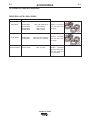
WIRE TYPE
Steel Wires:
Cored Wires:
Aluminum Wires:
KITS ELECTRODE SIZE
KP1505-030S .023-.030 (0.6-0.8mm)
KP1505-035S .035 (0.9mm)
KP1505-040S .040 (1.0mm)
KP1505-045S .045 (1.2mm)
KP1505-035C .030-.035" (0.8-0.9mm)
KP1505-045C .040-.045" (1.0-1.2mm)
KP1507-3/64A 3/64" (1.2mm)
OPTIONAL KITS AND ACCESSORIES
Includes: 4 V groove
drive rolls and inner
wire guide.
Includes: 4 Knurled
drive rolls and inner
wire guide.
Includes: 4 polished
U groove drive rolls,
outer wire guide and
inner wire guide.
DRIVE ROLL KITS 4 ROLL DRIVE

C-2
ACCESSORIES
C-2
AutoDrive
®
4R100
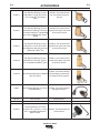
K1500-4
K1500-5
K489-7
K515-xx
K565-xx
K1546-1
Gun Receiver Bushing (for gun
with K466-3 Lincoln gun connec-
tors; compatible with Miller
®
guns.)
Gun Receiver Bushing (compatible
with Oxo
®
guns.)
Gun Receiver Bushing (for Lincoln
Fast-Mate guns.)
Wire Conduit
Wire Conduit
Incoming Bushing, for Lincoln
Conduit .025- 1/16" (0.6 - 1.6mm)
wire. Compatible with Electron
Beam Conduit.
Includes: Gun receiver bush-
ing with hose nipple, set screw
and hex key wrench.
Includes: Gun receiver bushing
with hose nipple, 4 guide tubes,
set screw and hex key wrench.
Includes: Gun receiver bushing
with trigger connector.
Requires K1546-1
Requires K1546-1
Includes: Incoming bushing and
hex key wrench.
K1500-1
K1500-2
K1500-3
Gun Receiver Bushing (for guns
with K466-1 Lincoln gun connec-
tors; Innershield
®
and Subarc
guns)
Gun Receiver Bushing (for guns
with K466-2, K466-10 Lincoln gun
connectors; Magnum
®
200/300/400
guns and compatible with Tweco
®
#2-#4)
Gun Receiver Bushing (for guns
with K613-7 Lincoln gun connec-
tors; Magnum
®
550 guns and com-
patible with Tweco
®
#5)
Includes: Gun receiver bush-
ing, set screw and hex key
wrench.
Includes: Gun receiver bush-
ing with hose nipple, set screw
and hex key wrench.
Includes: Gun receiver bush-
ing with hose nipple, set screw
and hex key wrench.

C-3
ACCESSORIES
C-3
AutoDrive
®
4R100
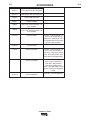
K2175-1
K2175-2
K895-2
K836-1
K884-5
K884-6
K1796-xx
K2593-xx
K1785-xx
K2709-xx
K1733-1
500 lb Accu-Pak
®
Box Payoff Kit
1000 lb Accu-Pak
®
Box Payoff Kit
Rotary Wire Dispenser
Dereeler Adapter
Accu-Trak
®
Drum Payoff Kit – 20
inch diameter
Accu-Trak
®
Drum Payoff Kit – 23
inch diameter
Coaxial Cables
Coaxial Cables
Wire Drive Cables
Wire Drive Cables
Wire Straightener
Includes: 1 cable of length “xx”
feet. 14-pin connectors on
both ends. Cable length can-
not be extended by connecting
K1785 cables together.
Includes: 1 cable of length “xx”
feet. 14-pin connectors on
both ends. Has collars at both
ends. Used with FANUC arms
that have an integrated cable.
Includes: 1 cable of length “xx”
feet. 14-pin connectors on
both ends. May be daisy
chained to make a longer
cable. Used with FANUC arms
that do not have an integrated
cable.
Includes: 1 wire straightener
La page est en cours de chargement...
La page est en cours de chargement...
La page est en cours de chargement...
La page est en cours de chargement...
La page est en cours de chargement...
La page est en cours de chargement...
La page est en cours de chargement...
La page est en cours de chargement...
La page est en cours de chargement...
La page est en cours de chargement...
La page est en cours de chargement...
La page est en cours de chargement...
-
 1
1
-
 2
2
-
 3
3
-
 4
4
-
 5
5
-
 6
6
-
 7
7
-
 8
8
-
 9
9
-
 10
10
-
 11
11
-
 12
12
-
 13
13
-
 14
14
-
 15
15
-
 16
16
-
 17
17
-
 18
18
-
 19
19
-
 20
20
-
 21
21
-
 22
22
-
 23
23
-
 24
24
-
 25
25
-
 26
26
-
 27
27
-
 28
28
-
 29
29
-
 30
30
-
 31
31
-
 32
32


Lincoln Electric AutoDrive 4R100 Mode d'emploi
- Catégorie
- Système de soudage
- Taper
- Mode d'emploi
dans d''autres langues
Documents connexes
-
Lincoln Electric Red-D-Arc DX500e Mode d'emploi
-
-
-
-
-
-
-
-
-
Lincoln Electric Ranger 305D Mode d'emploi