Miller MD000000 Le manuel du propriétaire
- Catégorie
- Système de soudage
- Taper
- Le manuel du propriétaire
Ce manuel convient également à

OWNER’S MANUAL
© 2019 MILLER Electric Mfg. LLC
OM-823 029899AA
2019−10
RHC-3, RHC-3GD34A, And
RHC-14 Remote Hand Controls
DANGER! − Indicates a hazardous situation which, if not
avoided, will result in death or serious injury. The possible
hazards are shown in the adjoining symbols or explained
in the text.
DANGER ! - Indique une situation dangereuse qui, si elle
n’est pas évitée, entraînera la mort ou des blessures
graves. Les éventuels risques sont représentés par les
symboles joints ou expliqués dans le texte.
Fsafe1 2013-10
Wear safety glasses with side shields.
Porter des lunettes de sécurité avec écrans latéraux.
Fsafe8 2013-10
Indicates a hazardous situation which, if not avoided,
could result in death or serious injury. The possible ha-
zards are shown in the adjoining symbols or explained in
the text.
Indique une situation dangereuse qui, si elle n’est pas
évitée, entraînera la mort ou des blessures graves. Les
éventuels risques sont représentés par les symboles
joints ou expliqués dans le texte.
Fsafe2 2013-10
Arc rays can burn eyes and skin − wear a welding helmet
with correct filter, and cover exposed skin with nonflam-
mable clothing.
Le rayonnement de l’arc peut provoquer des brûlures au
niveau des yeux ou de la peau – porter un casque protec-
teur muni d’un écran de filtre approprié et porter des vête-
ments non inflammables pour protéger toutes parties
exposées.
Fsafe11 2018-01
NOTICE
AVIS
Indicates statements not related to personal injury.
Signale des consignes non associées aux dommages
corporels.
Indicates special instructions.
Fournit des instructions spéciales.
Fsafe3 2013-10
Welding sparks can cause fire or explosion. Move flam-
mables away. Do not weld on closed tanks or barrels, or
on containers that have held combustibles − they can
explode. Clean tanks or barrels properly.
Les étincelles de soudure peuvent provoquer un incendie
ou une explosion. Ne pas souder de cuves ou de ton-
neaux, au risque qu’ils explosent. Nettoyer soigneuse-
ment les cuves ou tonneaux.
Fsafe9 2018-01
Beware of electric shock from welding electrode or wiring.
Touching the electrode while in contact with the work or
ground can cause electric shock. Always wear dry
gloves. Keep all panels and covers closed.
Attention au risque d’électrocution due au contact avec
l’électrode de soudage ou les fils. Le fait de toucher
l’électrode tout en étant en contact avec la pièce ou la
terre peut provoquer une électrocution. Toujours porter
des gants secs. Tous les panneaux et couvercles doivent
rester fermés.
Fsafe6 2018-01
Breathing welding fumes and gases can harm your
health. Welding requires good ventilation. If ventilation is
impossible, such as when welding in a confined space,
use an air-supplied respirator.
L’inhalation des fumées et des gaz de soudure peut être
dangereuse pour la santé. Une bonne ventilation est
nécessaire pour procéder au soudage. S’il est impossible
de ventiler, dans des lieux confinés par exemple, utiliser
un respirateur à alimentation d’air.
Fsafe10 2018-01
CALIFORNIA PROPOSITION 65 WARNINGS
WARNING: Cancer and Reproductive Harm − www.P65W
arnings.ca.gov
PROPOSITION CALIFORIENNE 65 AVERTISSEMENTS
AVERTISSEMENT : cancer et troubles de la reproduction − www.P65W
arnings.ca.gov
.
Fsafe26 2018-01

OM-823 Page 2
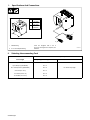
1. Specifications And Connections
141127-A
1 Twistlock Plug
2 5- Or 14-Pin Amphenol Plug
Units are equipped with a 20 ft
(6 m) cord. If a longer cord is required, see
Section 2.
A 7-1/2 in.
(191 mm)
B 9-1/2 in.
(241 mm)
C 8-3/4 in.
(222 mm)
B
C
A
1
2
2. Selecting Interconnecting Cord
Conductor Size (*AWG)
Cord Length Amperage Or Voltage Control RHC-14
Up to 20 ft (6 m) No. 16
Up to 20 ft (6 m) (GD Models) No. 14
21 to 100 ft (6 to 30 m) (GD Models) No. 12 No. 18 For Any Length
21 to 50 ft (6 to 15 m) No. 14
51 to 100 ft (16 to 31 m) No. 12
101 to 200 ft (31 to 61 m) No. 10
*AWG − American Wire Gauge

OM-823 Page 3
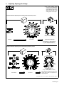
3. Adjusting Amperage Or Voltage
. On some welding power
sources, the front panel output
control setting does not matter
and the Remote Hand Control
adjusts the full range of the
welding power source output.
Ref. 122023-A / Ref. 141127-A / 039411-D / Ref. 159059 / Ref. 130214-A
Example Of Remote Amperage Control Without Output (Contactor) Control
Set Switch Set Control Adjust Remote Amperage
Example Of Remote Amperage Control With Output (Contactor) Control
Min
(40 A)
Max
(200 A)
In Example: Min = 40 A In Range B,
Output = 120 A (50% of 40 to 200)
Max = 200 A In Range B
Set Switches Set Control
Min
(5 A)
Max
(200 A)
Place switch in On position for open-circuit
voltage. When switch is in Off position no
output is present.
In Example: Min = 5 A
Output = 200 A (100% of 5 to 200)
Max = 200 A

OM-823 Page 4
4. Routine Maintenance
! Turn Off all power before maintaining.
3 Months
Everyday
Replace
Cracked
Parts
Replace
Unreadable
Labels
Cord(s)
Move Control From
Min. To Max.
5. Troubleshooting
Trouble Remedy
No amperage or voltage control. Set switches and controls on welding power source or generator (see Section 3*).
Check weld output on welding power source or generator.
Secure cord connections or replace cords, if necessary.
No output (contactor) control. Remote Hand Control switch in wrong position or control not so equipped.
Check switch settings and weld output on welding power source or generator.
Secure cord connections or replace cords, if necessary.
*See welding power source or generator Owner’s Manual.
6. Circuit Diagrams
150670-C
RHC-3
094231-B
RHC-3-GD34A
053656-A
RHC-14RHC-3 (100 ft)
210458-B

OM-823 Page 5
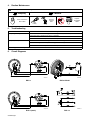
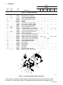
7. Parts List
Q
uantity
Description
Part
No.
Dia.
Mkgs.
Item
No.
RHC-14RHC-1
4
Figure 7-1. Complete Assembly .
Model
(50ft) (100ft)
RHC-3
(100ft)
RHC-3
GD34A
RHC
14
RHC
3
1 R1 222736 Rheostat, WW 150W 15 Ohm 1 1... .... ...... .. .... .................
1 R1 198087 Potentiometer, CP Std Slot... .... ...... ..
1T 2. W 1K Linear W/Fricttabs 1 1 1.............................. ......... ................. ....
1 R1 605960 Rheostat, WW 300W 34 Ohm 1... .... ...... .. .................
2 085220 Label, Caution Electric Circuit 1111 1 1... .............. .. .... .... .... .... .... ....
3 +021475 Wrapper 1 1 1... ............. .. ...................... ........... ....
3 +014417 Wrapper 1 1 1... ............. .. ............................ ................. ....
4 217193 Case Section, Base/Front/Rear 1 1... .............. .. .. ...........
4 109974 Case Section, Base/Front/Rear 1 1 1... .............. .. ........ ................. ....
4 234522 Case Section, Base/Front/Rear 1... .............. .. .....................
5 PLG1 605797 Plug, Twlk 3P3W 20A 125V 1 1... .. ..... .. ...... .................
5 PLG1 144310 Housing Plug & Pins, (Consisting Of) 111... .. ..... .. ..... ................. ....
134732 Terminal, Male 1 Pin 24-20 Wire 14 14 14.................... .... ...... ................. ....
143922 Clamp, Cable Strain Relief Sz 17 & 20 111.................... .... .... ................. ....
5 PLG1 032898 Plug, Twlk Grd 2P3W 15A 125V 1... .. ..... .. ...............
6 217029 Bushing, Strain Relief 1 1 1... .............. .. ........... ........... ....
217030 Nut, Locking Strain Relief 1/2 In Npt .270 111.................... .. ........... ....
7 204213 Cable, Pwr 16Ga 3/C (Order By Ft) 1... .............. ..
7 270796 Cable, Port No. 20 5/C (Order By Ft) 20Ft 50Ft 100Ft... .............. .. .... ............... .
7 600349 Cable, Port No.14 3/C (Order By Ft) 20Ft... .............. .. .........
7 600795 Cable, Port No.12 3/C (Order By Ft) 100Ft... .............. .. ...............
8 186019 Label, Model/Stock Number 1... .............. .. .....
8 210459 Label, Model/Stock Number 1... .............. .. ........................
9 171007 Knob, Pointer 1 1... .............. .. .................. .................
9 193919 Knob, Pointer 1 1 1... .............. .. ........................ ................. ....
9 019602 Knob, Pointer 1... .............. .. ...............................
10 148719 Nameplate 1 1... .............. .. .................... .................
10 130214 Nameplate 1 1 1... .............. .. .......................... ................. ....
10 148717 Nameplate, Rhc-3Gd 34A 1... .............. .. ....................
S1 011609 Switch, Tgl SPDT 15A 125VAC 1 1 1.......... ...... .. ........ ................. ....
1
2
3
4
5
9
10
6
7
8
141128-A
Figure 7-1. Complete Assembly (RHC-3 Illustrated)
+When ordering a component originally displaying a precautionary label, the label should also be ordered.
BE SURE TO PROVIDE MODEL AND STYLE NUMBER WHEN ORDERING REPLACEMENT PARTS.
-
 1
1
-
 2
2
-
 3
3
-
 4
4
-
 5
5


Miller MD000000 Le manuel du propriétaire
- Catégorie
- Système de soudage
- Taper
- Le manuel du propriétaire
- Ce manuel convient également à
dans d''autres langues
- English: Miller MD000000 Owner's manual
Documents connexes
-
Miller GOUGE REMOTE CONTROL 258046 Le manuel du propriétaire
-
Miller MA27 Le manuel du propriétaire
-
-
-
-
-
-
-