
AORUS MODEL S
GAMING DESKTOP PC
(GB-AMSR9N8I-20A1)
User's Manual
Rev. 1001
For more product details, please visit GIGABYTE's website.
To reduce the impacts on global warming, the packaging materials of this product
are recyclable and reusable. GIGABYTE works with you to protect the environment.

Copyright
© 2021 GIGA-BYTE TECHNOLOGY CO., LTD. All rights reserved.
The trademarks mentioned in this manual are legally registered to their respective owners.
Disclaimer
Information in this manual is protected by copyright laws and is the property of GIGABYTE.
Changes to the specications and features in this manual may be made by GIGABYTE
without prior notice.
No part of this manual may be reproduced, copied, translated, transmitted, or published in any
form or by any means without GIGABYTE's prior written permission.
Documentation Classications
In order to assist in the use of this product, GIGABYTE provides the following types of
documentations:
For quick set-up of the product, read the Quick Startup Guide included with the product.
For detailed product information, carefully read the User's Manual.
For product-related information, check on our website at: https://www.gigabyte.com

- 3 -
Table of Contents
Box Contents ...................................................................................................................4
Chapter 1 Hardware Installation .....................................................................................5
1-1 Safety Information ............................................................................................ 5
1-2 Hardware Information ....................................................................................... 6
System Overview ....................................................................................................................6
Front View ..............................................................................................................................6
Back View-A ...........................................................................................................................7
Back View-B ...........................................................................................................................9
1-3 Getting Started ............................................................................................... 10
Connecting Peripheral Devices ............................................................................................10
Connecting the Power Cord .................................................................................................11
Turning On ............................................................................................................................ 11
Chapter 2 BIOS Setup ..................................................................................................12
2-1 Entering the BIOS Setup ................................................................................ 12
2-2 Setting the BIOS Display Language ............................................................... 13
2-3 Setting Administrator/User Password ............................................................. 14
2-4 Loading Optimized Defaults ........................................................................... 15
2-5 Saving the BIOS Settings and Exiting ............................................................ 16
Chapter 3 Appendix ......................................................................................................17
Using Q-Flash Plus ................................................................................................... 17
Regulatory Notices .................................................................................................... 18
Contact Us ................................................................................................................ 21

- 4 -
Box Contents
5AORUS MODEL S GAMING DESKTOP PC
5Quick Start Guide
5Antennas
5Power cord
The box contents above are for reference only and the actual items shall depend on the product package you obtain.
The box contents are subject to change without notice.

- 5 -
1-1 Safety Information
•Before connecting to the power outlet, make sure that the voltage rating of the power cable is
compatible with the power specication in the country where you are located.
•The power cord plug must be connected to a properly wired and grounded power outlet.
•Be sure that the power outlet you plug the power cord into is easily accessible and located
as close to the equipment operator as possible. When you need to disconnect power to the
equipment, be sure to unplug the power cord from the electrical outlet.
•Do not touch the plug with wet hands, otherwise easily cause electric shock.
•Protect the power cord from being tread upon or pinched, particularly at the plug.
•To avoid damage of internal component, do not place the product on a vibrating surface.
•Operating temperature: 5~35oC.
•Do not place the product near any heat sources such as electric radiators, heat registers,
stoves or other devices (including ampliers) that produce heat.
•Do not place the product in a conned space; make sure to use it in a well-ventilated place.
•The holes or openings on this product are for ventilation to ensure reliable operation of the
product and to protect it from overheating. Do not cover or block the ventilation holes with
any objects.
•Never push objects of any kind into this product through cabinet slots as they may touch
dangerous voltage points or short-out parts that could result in a re or electric shock. Never
spill liquid of any kind onto or into the product.
•Do not use this product near water, drinks, or all types of liquids. Do not expose this apparatus
to rain, liquid or moisture. Failure to do so may result in electric shock or damage. This product
is not water proof or oil-proof.
•Clean the equipment with a soft, dry cloth.
•The manufacturer species that the thumbscrews normally should be tightened with a
screwdriver, use of thumbscrews is not considered to compromise the basic principles of
safety associated with the Safety Standard.
•Warning! Danger of explosion if the battery is replaced with an incorrect model. Refer to the
manufacturer's instruction manual to handle the used battery.
•Do not remove the casing of this product to avoid causing safety issues. Do not make mechanical
or electrical modications to the equipment to avoid causing safety issues.
Chapter 1 Hardware Installation

- 6 -
1-2 Hardware Information
System Overview
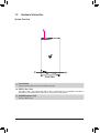
Front View
Power Button
The power button allows users to turn on/off the computer.
USB 3.2 Gen 1 Port
The USB 3.2 Gen 1 port supports the USB 3.2 Gen 1 specication and is compatible to the USB 2.0
specication. The maximum power output is 5V. Use this port for USB devices.
Audio/Microphone Jack
The line out/Mic in jack.

- 7 -
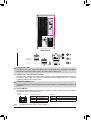
Back View-A
USB 3.2 Gen 1 Port
The USB 3.2 Gen 1 port supports the USB 3.2 Gen 1 specication and is compatible to the USB 2.0
specication. The maximum power output is 5V. Use this port for USB devices.
USB 3.2 Gen 1 Port (Q-Flash Plus Port)
The USB 3.2 Gen 1 port supports the USB 3.2 Gen 1 specication and is compatible to the USB 2.0 specication.
The maximum power output is 5V. Use this port for USB devices. Before using Q-Flash Plus (Note), make sure
to insert the USB ash drive into this port rst.
Q-Flash Plus Button (Note)
This button allows you to update the BIOS when the power connector is connected but the system is not
powered on.
RJ-45 LAN Port
The Gigabit Ethernet LAN port provides Internet connection at up to 2.5 Gbps data rate. The following
describes the states of the LAN port LEDs.
Activity LED
Connection/
Speed LED
LAN Port
Activity LED:Connection/Speed LED:
State Description
Orange 2.5 Gbps data rate
Green 1 Gbps data rate
Off 100/10 Mbps data rate
State Description
Blinking Data transmission or receiving is occurring
Off No data transmission or receiving is occurring
(Note) To enable Q-Flash Plus function, refer to Chapter 3.

- 8 -
USB 3.2 Gen 2 Type-A Port (Red)
The USB 3.2 Gen 2 port supports the USB 3.2 Gen 2 specication and is compatible to the USB 3.2
Gen 1 and USB 2.0 specication. The maximum power output is 5V. Use this port for USB devices.
USB Type-C® Port
The reversible USB port supports the USB 3.2 Gen 2 specication and is compatible to the USB 3.2 Gen 1
and USB 2.0 specication. The maximum power output is 5V. Use this port for USB devices.
SMA Antenna Connectors (2T2R)
Use this connector to connect an antenna.
Line In/Rear Speaker Out
The line in jack. Use this audio jack for line in devices such as an optical drive, walkman, etc.
Line Out/Front Speaker Out
The line out jack. This jack supports audio amplifying function. For better sound quality, it is recommended
that you connect your headphone/speaker to this jack (actual effects may vary by the device being used).
Mic In/Center/Subwoofer Speaker Out
The Mic in jack.
Tighten the antennas to the antenna connectors and then aim the antennas correctly for better
signal reception.
Audio Jack Congurations:
Jack Headphone/
2-channel 4-channel 5.1-channel 7.1-channel
Line In/Rear Speaker Out aaa
Line Out/Front Speaker Out a a a a
Mic In/Center/Subwoofer Speaker Out a a
Front Panel Line Out/Side Speaker Out a
To congure 7.1-channel audio, you have to use an HD front panel audio module and enable
the multi-channel audio feature through the audio driver.
•When removing the cable connected to a back panel connector, rst remove the cable from
your device and then remove it from the motherboard.
•When removing the cable, pull it straight out from the connector. Do not rock it side to side
to prevent an electrical short inside the cable connector.
Please visit GIGABYTE's website for details on conguring the audio software.

- 9 -
Back View-B
DisplayPort
The connector supports DisplayPort 1.4a version.
HDMI Port
The connector supports HDMI 2.1 version.
Be sure to connect the monitor cable to the graphics card.

- 10 -
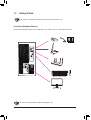
1-3 Getting Started
This product is designed and intended to be used in vertical position only.
Connecting Peripheral Devices
Connect your peripheral devices such as keyboard, mouse, monitor, and etc. to the desktop computer.
Be sure to connect the monitor cable to the graphics card.

- 11 -
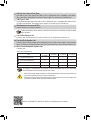
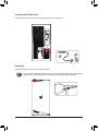
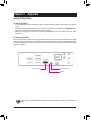
Connecting the Power Cord
Connect the included power cord to the desktop computer and a power outlet.
Turning On
Press the power button to turn on the desktop computer.
AB
It is recommended that the product be used in an open and well-ventilated area; keep a distance
of at least 10 cm around the product for ventilation to ensure proper system operation.

- 12 -
Chapter 2 BIOS Setup
Function Keys
•Because BIOS ashing is potentially risky, if you do not encounter problems using the current version of BIOS,
it is recommended that you not ash the BIOS. To ash the BIOS, do it with caution. Inadequate BIOS ashing
may result in system malfunction.
•It is recommended that you not alter the default settings (unless you need to) to prevent system instability or other
unexpected results. Inadequately altering the settings may result in system's failure to boot. If this occurs, try to
clear the CMOS values and reset the board to default values. (Refer to the "Load Optimized Defaults" section
for how to clear the CMOS values.)
2-1 Entering the BIOS Setup
To access the BIOS Setup program, press the <Delete> key during the POST when the power is turned on.
When the power is turned off, the battery on the motherboard supplies the necessary power to the CMOS to
keep the conguration values in the CMOS.
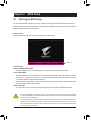
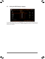
Startup Screen
The following startup Logo screen will appear when the computer boots.
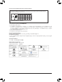
Function Keys:
<DEL>: BIOS SETUP\Q-FLASH
Press the <Delete> key to enter BIOS Setup or to access the Q-Flash utility in BIOS Setup.
<F12>: BOOT MENU
Boot Menu allows you to set the rst boot device without entering BIOS Setup. In Boot Menu, use the up
arrow key <h> or the down arrow key <i> to select the rst boot device, then press <Enter> to accept.
The system will boot from the device immediately.
Note: The setting in Boot Menu is effective for one time only. After system restart, the device boot order
will still be based on BIOS Setup settings.
<END>: Q-FLASH
Press the <End> key to access the Q-Flash utility directly without having to enter BIOS Setup rst.

- 13 -
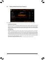
2-2 Setting the BIOS Display Language
To set the BIOS display language, go to the System Info. menu. The BIOS Language setting allows you to
select the default language used by the BIOS. The System Language setting allows you to select the default
language used by the BIOS.

- 14 -
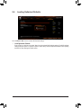
2-3 Setting Administrator/User Password
&Administrator Password
Allows you to congure an administrator password. Press <Enter> on this item, type the password, and
then press <Enter>. You will be requested to conrm the password. Type the password again and press
<Enter>. You must enter the administrator password (or user password) at system startup and when entering
BIOS Setup. Differing from the user password, the administrator password allows you to make changes to
all BIOS settings.
&User Password
Allows you to congure a user password. Press <Enter> on this item, type the password, and then press
<Enter>. You will be requested to conrm the password. Type the password again and press <Enter>.
You must enter the administrator password (or user password) at system startup and when entering BIOS
Setup. However, the user password only allows you to make changes to certain BIOS settings but not all.
To cancel the password, press <Enter> on the password item and when requested for the password, enter
the correct one rst. When prompted for a new password, press <Enter> without entering any password.
Press <Enter> again when prompted to conrm.
NOTE: Before setting the User Password, be sure to set the Administrator Password rst.
Go to the Boot menu to set the administrator password or user password for your desktop computer.

- 15 -
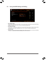
Go to the Save & Exit menu to load the BIOS default settings.
2-4 Loading Optimized Defaults
&Load Optimized Defaults
Press <Enter> on this item and select Yes to load the optimal BIOS default settings. The BIOS defaults
settings help the system to operate in optimum state. Always load the Optimized defaults after updating
the BIOS or after clearing the CMOS values.

- 16 -
2-5 Saving the BIOS Settings and Exiting
&Save & Exit Setup
Press <Enter> on this item and select Yes. This saves the changes to the CMOS and exits the BIOS Setup
program. Select No or press <Esc> to return to the BIOS Setup Main Menu.
&Exit Without Saving
Press <Enter> on this item and select Yes. This exits the BIOS Setup without saving the changes made
in BIOS Setup to the CMOS. Select No or press <Esc> to return to the BIOS Setup Main Menu.
&Boot Override
Allows you to select a device to boot immediately. Press <Enter> on the device you select and select Yes
to conrm. Your system will restart automatically and boot from that device.

- 17 -
Chapter 3 Appendix
Using Q-Flash Plus
If you choose to update the BIOS manually, rst make sure that your system is off (S5 shutdown
state).
A. Before You Begin:
1. From GIGABYTE's website, download the latest compressed BIOS update le that matches your product
model.
2. Uncompress the downloaded BIOS le, save it to your USB ash drive, and rename it to GIGABYTE.bin.
(Note: The USB ash drive must use FAT32/16/12 le system.)
3. Please turn on the power supply before connecting the USB ash drive to the Q-Flash Plus port on the
back panel.
B. Using Q-Flash Plus
Press the Q-Flash Plus button and the system will automatically search and match the BIOS le in the USB
ash drive on the Q-Flash Plus port. The QFLED and the Q-Flash Plus button on the rear panel will ash during
the BIOS matching and ashing process. Wait for 6-8 minutes and the LEDs will stop ashing when the BIOS
ashing is complete.
Q-Flash Plus Button
QFLED
Q-Flash Plus Port

- 18 -
Supplier's Declaration of Conformity
47 CFR § 2.1077 Compliance Information
Product Name: GIGABYTE DESKTOP PC
Trade Name: GIGABYTE
Model Number: GB-AMSR9N8I-20A1
Responsible Party – U.S. Contact Information: G.B.T. Inc.
Address: 17358 Railroad street, City Of Industry, CA91748
Tel.: 1-626-854-9338
Internet contact information: https://www.gigabyte.com
FCC Compliance Statement:
This device complies with Part 15 of the FCC Rules, Subpart B, Unintentional Radiators.
Operation is subject to the following two conditions: (1) This device may not cause harmful interference, and (2) this
device must accept any interference received, including interference that may cause undesired operation.
Antenna use:
In order to comply with FCC RF exposure limits, low gain integrated
antennas should be located at a minimum distance of 7.9 inches (20 cm)
or more from the body of all persons.
Explosive Device Proximity Warning
Warning: Do not operate a portable transmitter (such as a wireless network
device) near unshielded blasting caps or in an explosive environment
unless the device has been modied to be qualied for such use.
Antenna Warning
The wireless adapter is not designed for use with high-gain antennas.
Use On Aircraft Caution
Caution: Regulations of the FCC and FAA prohibit airborne operation of
radio-frequency wireless devices because their signals could interfere with
critical aircraft instruments.
Other Wireless Devices
Safety Notices for Other Devices in the Wireless Network: Refer to the
documentation supplied with wireless Ethernet adapters or other devices
in the wireless network.
Canada, Canada-Industry Notice:
This device complies with Industry Canada license-exempt RSS
standard(s). Operation is subject to the following two conditions:
(1) this device may not cause interference, and
(2) this device must accept any interference, including interference that
may cause undesired operation of the device.
Cet appareil est conforme aux normes Canada d'Industrie de RSS
permis-exempt. L'utilisation est assujetti aux deux conditions suivantes:
(1) le dispositif ne doit pas produire de brouillage préjudiciable, et
(2) ce dispositif doit accepter tout brouillage reçu, y compris un brouillage
susceptible de provoquer un fonctionnement indésirable.
Caution: When using IEEE 802.11a wireless LAN, this product is restricted
to indoor use due to its operation in the 5.15-to 5.25-GHz frequency
range. Industry Canada requires this product to be used indoors for the
frequency range of 5.15 GHz to 5.25 GHz to reduce the potential for
harmful interference to co-channel mobile satellite systems. High power
radar is allocated as the primary user of the 5.25-to 5.35-GHz and 5.65 to
5.85-GHz bands. These radar stations can cause interference with and/or
damage to this device. The maximum allowed antenna gain for use with
this device is 6dBi in order tocomply with the E.I.R.P limit for the 5.25-to
5.35 and 5.725 to 5.85 GHz frequency range in point-to-point operation. To
comply with RF exposure requirements all antennas should be located at a
minimum distance of 20cm, or the minimum separation distance allowed
by the module approval, from the body of all persons.
Attention: l'utilisation d'un réseau sans l IEEE802.11a est restreinte à
une utilisation en intérieur à cause du fonctionnement dansla bande de
fréquence 5.15-5.25 GHz. Industry Canada requiert que ce produit soit
utilisé à l'intérieur des bâtiments pour la bande de fréquence 5.15-5.25
GHz an de réduire les possibilités d'interférences nuisibles aux canaux
co-existants des systèmes de transmission satellites. Les radars de
puissances ont fait l'objet d'une allocation primaire de fréquences dans
les bandes 5.25-5.35 GHz et 5.65-5.85 GHz. Ces stations radar peuvent
créer des interférences avec ce produit et/ou lui être nuisible. Le gain
d'antenne maximum permissible pour une utilisation avec ce produit est de
6 dBi an d'être conforme aux limites de puissance isotropique rayonnée
équivalente (P.I.R.E.) applicable.
dans les bandes 5.25-5.35 GHz et 5.725-5.85 GHz en fonctionnement
point-à-point. Pour se conformer aux conditions d'exposition de RF toutes
les antennes devraient être localisées à une distance minimum de 20 cm,
ou la distance de séparation minimum permise par l'approbation du module,
du corps de toutes les personnes.
Regulatory Notices
United States of America, Federal Communications Commission Statement
The FCC with its action in ET Docket 96-8 has adopted a safety standard for human exposure to radio frequency (RF) electromagnetic energy emitted
by FCC certied equipment. The Intel PRO/Wireless 5000 LAN products meet the Human Exposure limits found in OET Bulletin 65, 2001, and ANSI/
IEEE C95.1, 1992. Proper operation of this radio according to the instructions found in this manual will result in exposure substantially below the FCC's
recommended limits.
The following safety precautions should be observed:
•Do not touch or move antenna while the unit is transmitting or receiving.
•Do not hold any component containing the radio such that the antenna is very close or touching any exposed parts of the body, especially the face
or eyes, while transmitting.
•Do not operate the radio or attempt to transmit data unless the antenna is connected; if not, the radio may be damaged.
•Use in specic environments:
- The use of wireless devices in hazardous locations is limited by the constraints posed by the safety directors of such environments.
- The use of wireless devices on airplanes is governed by the Federal Aviation Administration (FAA).
- The use of wireless devices in hospitals is restricted to the limits set forth by each hospital.

- 19 -
European Union (EU) CE Declaration of Conformity
This device complies with the following directives: Electromagnetic
Compatibility Directive 2014/30/EU, Low-voltage Directive 2014/35/EU,
Radio Equipment Directive 2014/53/EU, ErP Directive 2009/125/EC, RoHS
directive (recast) 2011/65/EU & the 2015/863 Statement.
This product has been tested and found to comply with all essential
requirements of the Directives.
European Union (EU) RoHS (recast) Directive 2011/65/EU & the
European Commission Delegated Directive (EU) 2015/863 Statement
GIGABYTE products have not intended to add and safe from hazardous
substances (Cd, Pb, Hg, Cr+6, PBDE, PBB, DEHP, BBP, DBP and DIBP).
The parts and components have been carefully selected to meet RoHS
requirement. Moreover, we at GIGABYTE are continuing our efforts to
develop products that do not use internationally banned toxic chemicals.
European Union (EU) Community Waste Electrical & Electronic
Equipment (WEEE) Directive Statement
GIGABYTE will fulll the national laws as interpreted from the 2012/19/
EU WEEE (Waste Electrical and Electronic Equipment) (recast) directive.
The WEEE Directive species the treatment, collection, recycling and
disposal of electric and electronic devices and their components. Under
the Directive, used equipment must be marked, collected separately, and
disposed of properly.
WEEE Symbol Statement
The symbol shown below is on the product or on its packaging,
which indicates that this product must not be disposed of with
other waste. Instead, the device should be taken to the waste
collection centers for activation of the treatment, collection,
recycling and disposal procedure.
For more information about where you can drop off your waste equipment
for recycling, please contact your local government ofce, your household
waste disposal service or where you purchased the product for details of
environmentally safe recycling.
End of Life Directives-Recycling
The symbol shown below is on the product or on its packaging,
which indicates that this product must not be disposed of with
other waste. Instead, the device should be taken to the waste
collection centers for activation of the treatment, collection,
recycling and disposal procedure.
Déclaration de Conformité aux Directives de l'Union européenne (UE)
Cet appareil portant la marque CE est conforme aux directives de l'UE
suivantes: directive Compatibilité Electromagnétique 2014/30/UE, directive
Basse Tension 2014/35/UE, directive équipements radioélectriques
2014/53/UE, la directive RoHS II 2011/65/UE & la déclaration 2015/863.
La conformité à ces directives est évaluée sur la base des normes
européennes harmonisées applicables.
European Union (EU) CE-Konformitätserklärung
Dieses Produkte mit CE-Kennzeichnung erfüllen folgenden EU-
Richtlinien: EMV-Richtlinie 2014/30/EU, Niederspannungsrichtlinie
2014/35/EU, Funkanlagen Richtlinie 2014/53/EU, RoHS-Richtlinie
2011/65/EU erfüllt und die 2015/863 Erklärung.
Die Konformität mit diesen Richtlinien wird unter Verwendung der
entsprechenden Standards zurEuropäischen Normierung beurteilt.
CE declaração de conformidade
Este produto com a marcação CE estão em conformidade com das
seguintes Diretivas UE: Diretiva Baixa Tensão 2014/35/EU; Diretiva
CEM 2014/30/EU; Diretiva RSP 2011/65/UE e a declaração 2015/863.
A conformidade com estas diretivas é vericada utilizando as normas
europeias harmonizadas.
CE Declaración de conformidad
Este producto que llevan la marca CE cumplen con las siguientes
Directivas de la Unión Europea: Directiva EMC 2014/30/EU, Directiva
de bajo voltaje 2014/35/EU, Directiva de equipamentos de rádio 2014/53/
EU, Directiva RoHS 2011/65/EU y la Declaración 2015/863.
El cumplimiento de estas directivas se evalúa mediante las normas
europeas armonizadas.
CE Dichiarazione di conformità
I prodotti con il marchio CE sono conformi con una o più delle seguenti
Direttive UE, come applicabile: Direttiva EMC 2014/30/UE, Direttiva sulla
bassa tensione 2014/35/UE, Direttiva di apparecchiature radio 2014/53/
UE, Direttiva RoHS 2011/65/EU e Dichiarazione 2015/863.
La conformità con tali direttive viene valutata utilizzando gli Standard
europei armonizzati applicabili.
Deklaracja zgodności UE Unii Europejskiej
Urządzenie jest zgodne z następującymi dyrektywami: Dyrektywa
kompatybilności elektromagnetycznej 2014/30/UE, Dyrektywa
niskonapięciowej 2014/35/UE, Dyrektywa urządzeń radiowych 2014/53/
UE, Dyrektywa RoHS 2011/65/UE i dyrektywa2015/863.
Niniejsze urządzenie zostało poddane testom i stwierdzono jego
zgodność z wymaganiami dyrektywy.
ES Prohlášení o shodě
Toto zařízení splňuje požadavky Směrnice o Elektromagnetické
kompatibilitě 2014/30/EU, Směrnice o Nízkém napětí 2014/35/EU,
Směrnice o rádiových zařízeních 2014/53/EU, Směrnice RoHS 2011/65/
EU a 2015/863. Tento produkt byl testován a bylo shledáno, že splňuje
všechny základní požadavky směrnic.
EK megfelelőségi nyilatkozata
A termék megfelelnek az alábbi irányelvek és szabványok
követelményeinek, azok a kiállításidőpontjában érvényes, aktuális
változatában: EMC irányelv 2014/30/EU, Kisfeszültségű villamos
berendezésekre vonatkozó irányelv 2014/35/EU, rádióberendezések
irányelv 2014/53/EU, RoHS irányelv 2011/65/EU és 2015/863.
Δήλωση συμμόρφωσης ΕΕ
Είναι σε συμμόρφωση με τις διατάξεις των παρακάτω Οδηγιών
της Ευρωπαϊκής Κοινότητας: Οδηγία 2014/30/ΕΕ σχετικά με την
ηλεκτρομαγνητική συμβατότητα, Οοδηγία χαμηλή τάση 2014/35/EU,
Οδηγία 2014/53/ΕΕ σε ραδιοεξοπλισμό, Οδηγία RoHS 2011/65/ΕΕ
και 2015/863.
Η συμμόρφωση με αυτές τις οδηγίες αξιολογείται χρησιμοποιώντας τα
ισχύοντα εναρμονισμένα ευρωπαϊκά πρότυπα.
EU contact point:
GIGABYTE TECHNOLOGY Trading GmbH
Am Stadtrand 63, 22047 Hamburg, Germany
Tel: +49-40-25 33 040
UK contact point:
GBT TECH. CO. LTD
13 Warren Yard, Wolverton Mill, Milton Keynes MK12 5NW, United
Kingdom
Tel: +44 (0)1908 322878
Under Industry Canada regulations, this radio transmitter may only operate
using an antenna of a type and maximum (or lesser) gain approved for
the transmitter by Industry Canada. To reduce potential radio interference
to other users, the antenna type and its gain should be chosen so that
the equivalent isotropically radiated power (e.i.r.p.) is not more than that
necessary for successful communication.
Conformément à la réglementation d'Industrie Canada, le présent émetteur
radio peut fonctionner avec une antenne d'un type et d'un gain maximal
(ou inférieur) approuvé pour l'émetteur par Industrie Canada. Dans le
but de réduire les risques de brouillage radio électrique à l'intention des
autres utilisateurs, il faut choisir le type d'antenne et son gain de sorte
que la puissance isotrope rayonnée équivalente (p.i.r.e.) ne dépasse pas
l'intensité nécessaire à l'établissement d'une communication satisfaisante.

- 20 -
Taiwan NCC Wireless Statements / 無線設備警告聲明:
低功率電波輻射性電機管理辦法
(1) 取得審驗證明之低功率射頻器材,非經核准,公司、商號或使用者均不得擅自變更頻率、加大功率或變更原設計之特
性及功能。低功率射頻器材之使用不得影響飛航安全及干擾合法通信;經發現有干擾現象時,應立即停用,並改善至
無干擾時方得繼續使用。前述合法通信,指依電信管理法規定作業之無線電通信。低功率射頻器材須忍受合法通信或
工業、科學及醫療用電波輻射性電機設備之干擾。
(2) 應避免影響附近雷達系統之操作。
(3) 高增益指向性天線只得應用於固定式點對點系統。
Korea KCC NCC Wireless Statement:
5,25GHz - 5,35 GHz 대역을 사용하는 무선 장치는 실내에서만 사용하도록 제한됩니다.
Korea EMC Warning Statement:
이 기기는 업무용 환경에서 사용할 목적으로 적합성평가를 받은 기기로서 가정용 환경에서 사용하는 경우 전파간섭의
우려가 있습니다.
Japan Wireless Statement:
5.15 GHz 帯 ~ 5.35 GHz 帯: 屋内のみの使用。
Wireless module country approvals:
Wireless module manufacturer: Intel® Corporation
Wireless module model name: AX200NGW
European Community Radio Equipment Directive Compliance Statement:
This equipment complies with all the requirements and other relevant provisions of Radio Equipment Directive 2014/53/EU.
This equipment is suitable for home and ofce use in all the European Community Member States and EFTA Member States.
The low band5.15 -5.35 GHz is for indoor use only.
AT BE BG CH CY CZ DE
DK EE EL ES FI FR HR
HU IE IS IT LI LT LU
LV MT NL PL PT RO SE
SI SK TR UK
Wireless module manufacturer: Intel® Corporation SAS
Wireless module model name: AX200NGW
La page est en cours de chargement...
-
 1
1
-
 2
2
-
 3
3
-
 4
4
-
 5
5
-
 6
6
-
 7
7
-
 8
8
-
 9
9
-
 10
10
-
 11
11
-
 12
12
-
 13
13
-
 14
14
-
 15
15
-
 16
16
-
 17
17
-
 18
18
-
 19
19
-
 20
20
-
 21
21


Gigabyte GB-AMSR9N8I-20A1 Aorus S Gaming Desktop PC Manuel utilisateur
- Taper
- Manuel utilisateur
- Ce manuel convient également à
dans d''autres langues
Documents connexes
-
Gigabyte AORUS MODEL X 11th Le manuel du propriétaire
-
GIGA-BYTE TECHNOLOGY AORUS MODEL S 11th Manuel utilisateur
-
-
-
-
-
-
-
-