
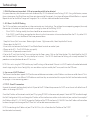
Net2 Plus and Power supplies
Paxton
ins-20603

1
1
2
4
3
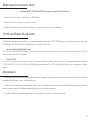
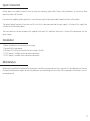
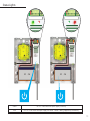
Mounting

1 2
1
2
4
3
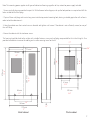
320 mm
232 mm
9 “
5.4“
3.18 “
10.5 “
1 “
12.6”
136 mm
116 mm
25 mm
81 mm
6.4 “
162 mm
2.7 “
4.5“
68 mm
268 mm
0.6 “
15 mm
6.6 “
167 mm
200 mm
7.9”
200 mm
7.9”
80
3.1”
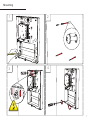
Note: This mounting process applies to all types of cabinet and housing regradless of size, material or power supply included.
1. Screws and wall plugs are provided in a parts kit. With reference to the diagram, mark up the hole positions as required and drill the
holes suitable for No 8 wall plugs.
2. Tap in all three wall plugs and insert a long screw into the top, central mounting hole, leaving a suitable gap to the wall surface in
order to slot the cabinet over it.
3. Hang the cabinet over the inserted screw as directed and tighten until secure. If the cabinet is not suciently secure, be wary of
the unit falling.
4. Secure the cabinet with the two lower screws.
This housing should be xed to the surface with suitable fasteners; screws and wall plugs are provided for this in the tting kit. Also
provided are cable ties to secure the cabling and a smaller securing screw for the lid.
Metal cabinet Plastic cabinet

3
0V
Net2 plus
0V
0V
0V
0V
0V
PSU
OK
0V
0V
ARM
SENSE
N.C.
N.O
1
2
COM
N.C.
N.O
COM
Data/D0
Clock/D1
CAT5
RS485
Media
Detect
0V
10
TX RX
100
Data/D0
Clock/D1
Media
Detect
10/100 Ethernet
N.C.
N.O
COM
12V - 24V
12V
1
2
12V
LED
LED
LED
12V
LED
LED
LED
LED
EXIT
EXIT
PSU
12V DC
12V DC
I
0V
Net2 plus
0V
0V
0V
0V
0V
PSU
OK
0V
0V
ARM
SENSE
N.C.
N.O
1
2
COM
N.C.
N.O
COM
Data/D0
Clock/D1
CAT5
RS485
Media
Detect
0V
10
TX RX
100
Data/D0
Clock/D1
Media
Detect
10/100 Ethernet
N.C.
N.O
COM
12V - 24V
12V
1
2
12V
LED
LED
LED
12V
LED
LED
LED
LED
EXIT
EXIT
PSU
12V DC
12V DC
I
0V
0V
0V
0V
N.C.
N.O
2
COM
N.C.
N.O
COM
Data/D0
Clock/D1
CAT5
RS485
0V
10
TX RX
100
Data/D0
Clock/D1
10/100 Ethernet
N.C.
N.O
COM
12V - 24V
12V
1
2
12V
LED
LED
LED
12V
LED
LED
LED
LED
EXIT
12V DC
12V DC
I
1
Paxton
Net2 plus
0V
0V
0V
0V
N.C.
N.O
2
COM
N.C.
N.O
COM
Data/D0
Clock/D1
CAT5
RS485
0V
10
TX RX
100
Data/D0
Clock/D1
10/100 Ethernet
N.C.
N.O
COM
12V - 24V
12V
1
2
12V
LED
LED
LED
12V
LED
LED
LED
LED
EXIT
12V DC
12V DC
I
1
Paxton
Net2 plus
0V
0V
0V
0V
N.C.
N.O
2
COM
N.C.
N.O
COM
Data/D0
Clock/D1
CAT5
RS485
0V
10
TX RX
100
Data/D0
Clock/D1
10/100 Ethernet
N.C.
N.O
COM
12V - 24V
12V
1
2
12V
LED
LED
LED
12V
LED
LED
LED
LED
EXIT
12V DC
12V DC
I
1
Paxton
Net2 plus
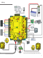
Wiring
The use of a Fail closed/Secure conguration shall be
determined by the local building codes and the local AHJ.

3 4
LED indications
Overview
• 12/24V (Green) Power LED.
• Relay 1 (Orange) The relay is energised - (NO/COM contacts are closed).
• Relay 2 (Orange) The relay is energised - (NO/COM contacts are closed).
• Alarm (Red) 12V Alarm output is active.
• Exit (Orange) The exit button contacts are closed.
• Contact (Orange) The door contacts are closed.
• Tamper (Orange) The tamper contacts are closed.
• PSU (Orange) The PSU contacts are closed.
• OK (Green ash) The internal software is running.
• Termination (Red) The on-board resistors are in place across the RS485 data pairs.
• Rx (Red) The ACU is receiving data (TCP/IP or RS485) - See also FAQ section.
• Tx (Green) The ACU is responding to data - (TCP/IP or RS485).
• Server Connected (Green) The TCP/IP interface is communicating with the PC Net2 server.
• Server Link - Green = 100 Mbit/s : Orange = 10 Mbit/s (TCP/IP speed).
A Net2 plus can connect to the Net2 PC using either an un-shielded RJ45 patch cable or an RS485 data line. This greatly increases the
number of installation options available to the installer.
Two typical site layouts are:
1 - The Net2 plus ACU’s can be individually connected to the Net2 PC via the site LAN network.
2 - Using a RS485 ‘daisy chain’ dataline, a Net2 plus ACU can be used as a TCP/IP converter for a line of Net2 plus ACU’s.
When used with an RS485 data line, on-board termination resistors can be put in circuit with a simple slide switch. Ensure that units
installed in the middle of the data line have this switch turned OFF.
The Net2 plus shall be installed within the protected premises as both the power and lock wiring is present at the PCB. A Tamper alarm
input is provided on the PCB - See the Input/Output Wiring section
The Net2 plus’ will continue to operate in a ‘standalone’ mode if the PC is shut down or the dataline is disconnected. Any Events that
occur during this period are stored in the Net2 plus and the PC is updated when it comes back on line.
The PC must be running for any ‘server based’ functions to operate. (Antipassback, Time and Attendance, etc)
To see the installation options available and important information relating to the installation and conguration of the Net2 plus, please
refer to the Application notes section on the website: paxton.info/2028

5
Input/Output wiring
Exit button
Door Bell - Relay 2
Door contact
Tamper switch
PSU monitoring
When the Exit terminal is shorted to 0V, the Exit LED will illuminate and the ACU will operate Relay 1. The reader/exit button Green LED will ash
during this period. More than one exit button can be wired in parallel. Relay 1 will remain transfered while the short to 0V remains.
Pressing the bell button on the keypad will result in Relay 2 being energized for 1 second. A bell sounder can be controlled by wiring one of the
bell feeds across COM / NO on the relay.
See Specication table for Output Ratings
A NO switch may be tted so that it is held closed while the door is shut.
When connected, Net2 will check the door position during access activity and will raise an Alarm in the event of a ‘Door Forced’ or ‘Door left open’
condition.
The ACU supplied in a plastic housing has a ‘NO’ tamper switch tted and pre-wired into the circuit board.
The Tamper LED will be ON when the switch is closed. Net2 will monitor the switch position and will raise an Alarm in the event of a ‘Tamper’
condition.
Connect to a UL listed burglar alarm unit for supervision.

5 6
Alarm sounder
Lock Wiring - Relay output
Panic hardware/ Fire Door Interface
Intruder alarm integration
This local alarm has a transistor ‘open drain’ output, (not a dry contact relay) and will switch 1A at 12V DC for a bell, light etc.
This local output can be turned on or o for each type of alarm and can be congured to sound continuously or intermittently to distinguish
between dierent alarm types.
This is a ONE door controller using a dry contact relay
The lock is wired across 12V and COM. A link (0V to NO or NC) is required, depending on lock type (Fail Closed / Open). Fit the supplied diode
across 12V and COM (Silver end to 12V ) to protect the relay contacts.
The dry relay contacts can be used to switch the power from an independent lock power supply. Wire the 0V to NC or NO and the lock to COM;
the +VCC supply is wired directly to the lock
The ACU supplied in a plastic housing has a ‘NO’ tamper switch tted and pre-wired into the circuit board.
The Tamper LED will be ON when the switch is closed. Net2 will monitor the switch position and will raise an Alarm in the event of a ‘Tamper’
condition.
Connect to a UL listed burglar alarm unit for supervision.
A re alarm system must be used to release all re doors. External relay contacts are held closed by the re alarm’s interface and will be dropped
during an alarm condition. The system is fail safe as the door will release even if the cable burns through.
A dedicated port for input and output signals is provided when integrating a Net2 plus ACU with an alarm system.
Please see: AN1035 - Integrating Net2 with an intruder alarm system www.paxton.info/91 or call Technical Support for further information.
Arm - Arm conrmation Push Button - Wire across 0V and Arm.
Sense - Wire a voltage free loop across 0V and Sense to monitor the alarms current status.
Set - Wire a voltage free loop across COM and N.O. or N.C. to provide a set signal for the alarm

7
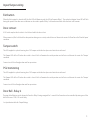
Cable type
Wiring installation and test
Connecting to the PC or other ACU’s via the RS485 data connection
An RS485 data line has a 1000 yds maximum. This distance can be increased with the use of Paxton high speed repeaters or by using
shorter independant data lines using multiple LAN connections controlled from the same PC.
The RS485 communications port is used for uploading rmware and user information as well as providing Event information to the PC.
1. Wire the components to the Net2 Plus Access Control Unit (ACU) as shown on the third page.
2. Press the exit button or in the absence of an exit button short the 0V and exit terminals to test the relay function. The lock Relay LED
will come on and the lock should release.
3. If there are any Readers or keypads wired to the Net2 plus, ensure that all the LED’s are lit on each reader/keypad. Test each reader/
keypad by presenting a token to the unit. It should beep and display a single ashing red or green LED. The reader or keypads default
indication has all the LED’s on. Access granted is denoted with a single ashing Green LED. Access Denied is a single ashing Red LED.
Note: Each time the Net2 Plus is powered on, it will run an internal health check. During this phase (about 5 secs) the OK LED will ash
quickly before changing to a slower heartbeat.
End of line termination - 120 ohm resistors must be linked across each data pair at the beginning AND end of the line. This can be done
on many units with a switch or jumpers. If not, resistors are provided with the converter.
Reader & Data Cable Screens
• Data cable screens and spare cores MUST be connected throughout.
• Reader and keypad screens where provided, should be connected to the Black 0V terminal.
The data line must be wired in a single daisy chain. The data connection to the PC may be located at any position along the data line.
90% of installation faults are caused by wiring errors on the RS485 data line.
Special attention to this area can save time and eort.
RS485 data line 1000 yrds 2 x twisted pairs - Belden 8723 or Cat5 equivalent
Input/Output 100 yrds 2 conductor - Alpha 1172C (22AWG) or equivalent
Reader/Keypad 82 feet 8 core, shielded - Belden 9538, Alpha 1298C (22AWG) or equivalent
Reader/Keypad 328 feet
8 core shielded cable - Belden 9540/ Belden 5306FE (18 AWG) or equivalent
TypeMax lengthUse

7 8
TCP/IP and RS485 LED indication
Maintenance
RS485 data line resistance check
The Net2 plus performs two functions. It is an access control unit and also a TCP/IP RS485 converter. Information can pass across the
PCB between the TCP/IP and RS485 data port but is not relevant to this ACU.
• Server Connected LED (Steady Green)
This LED shows that the TCP/IP interface is active and receiving data from the Net2 PC server. This includes all data for other ACU’s that
may be linked via the RS485 data port.
• Rx and Tx LED’s
These LED’s show the activity for this ACU only. This is same indication as seen on a Net2 classic ACU. It is not dependant on the source
(TCP/IP or RS485). The Rx LED will ash for all data being received and the Tx LED will only ash when this unit responds to its own
address.
It is advisable to ensure that any third party backup power supplies or recovery procedures are checked regularly to ensure that the
operation of the Paxton system is not compromised.
1 - Short circuiting, mutilation or incineration of the cells must be avoided to prevent one or more of the following occurrences; Release
of toxic materials, release of hydrogen and/or oxygen gas, rise in surface temperature.
2 - If a cell has leaked or vented the control unit must be replaced. The battery is not to be replaced
Power down all TCP/IP, USB and RS232 converters (individual and Net2 plus).
1. Check the resistance across each data pair is 60-80 ohms.
2. Check that there are no data line to screen shorts.
3. Check the screen of the data cable is continuous - this provides the 0V DC system reference

9
V0
802.3at
+-
+12V DC
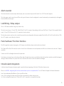
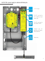
12V DC PoE+ power supply in cabinet with Net2 plus
+12V DC Outputs
Combined data and
power from a PSE (Power
source equipment)
This LED is on when the
input supply is healthy
This LED is on when the
unit is operating in high
power mode
Ethernet data

9 10
V0
802.3at
+-
+12V DC
The PoE (Power over Ethernet) supply is designed to draw power from a network cable that is provided with a remote PSE. (Power
source equipment).
This unit splits Ethernet data from the DC voltage. The voltage is available at two power connectors as 12V DC and the data is passed
unaltered to the Ethernet Out port.
This allows a Net2 plus to receive its power and data over a single cable connection without the need for an additional power supply.
The PoE+ power supply can be used in the high power mode (see specication table) if the power source equipment can detect this
request for additional power.
This is achieved by the Paxton supply through a hardware indication (capacitance). It is not able to provide this conrmation through
software (DLL classication).
1. Mount the cabinet as instructed on the rst page.
2. Connect the network cable to PoE In.
3. The Power LED will illuminate if power is available on this data line.
4. The PoE+ LED will illuminate if the high power rating is available.
5. 12V DC power is available at the two output connectors.
6. Network data is available at ‘Ethernet Out’
Following the completed installation of this equipment, no further maintenance or testing is required. It is advisable to ensure that any
third party backup power supplies or recovery procedures are checked regularly to ensure that the operation of the Paxton system is
not compromised. This product is not suitable for retail sale. All warranties are invalid if this product is not installed by a trained
technician.
Overview
High power mode
Installation
Maintenance

11
12V 7Ah
V21
V0
V21
V0
V42
V0
USP
V0
+-
+12V DC
+-
+24V DC
24V AC/DC
!
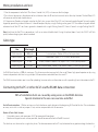
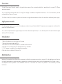
24V AC/DC power supply with Net2 plus
Note: Input power must be supplied via a
separately listed, class 2, plug-in transformer or
access control power supply (not provided as
part of this product). The power supply must
be listed to UL 294 or must be installed with
a listed surge protection device if listed to
another standard. This unit has provision for a
standby battery (not included).
+12V DC Outputs
+24V DC Outputs

11 12
12V 7Ah
V21
V0
V21
V0
V42
V0
USP
V0
+-
+12V DC
+-
+24V DC
24V AC/DC
!
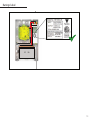
Anchor points are supplied inside the case to secure the incoming supply cable. There are also ‘knock-outs’ in the case to allow
convenient access for the cable.
Ensure that the supplied gland or grommet is used when passing the input power cable through any holes in the cabinet.
The battery backup function will not work until this unit has rst been connected to the input supply. It is the loss of this supply that
switches the unit to battery power.
The input cable must be passed around the supplied Ferrite core. This should be tted within 2 inches of the connection with the
power supply.
1. Mount the cabinet as instructed on the rst page.
2. Connect the Ac input power.
3. The Power LED will illuminate when the input supply is healthy
4. 12V DC power is available at the two output connectors.
5. 24V DC power is available at the two output connectors.
Input Connection
Installation
Following the completed installation of this equipment, no further maintenance or testing is required. It is advisable to ensure that any
third party backup power supplies or recovery procedures are checked regularly to ensure that the operation of the Paxton system is
not compromised.
Maintenance

13
V21
V0
V21
V0
V42
V0
USP
V0
12V 7Ah
V21
V0
V21
V0
V42
V0
USP
V0
12V 7Ah
V21
V0
V21
V0
V21
V0
USP
V0
0V
0V
0V
PSU
PSU /
0V
N.C.
N.O
1
2
COM
N.C.
N.O
COM
CAT5
RS485
RX
12V - 24V
12V
LED
EXIT
INPUT AC 100-240V
50 / 60 Hz
1.2A
OUTPUT DC 13.8V 2A
V21
V0
V21
V0
V21
V0
USP
V0
0V
0V
0V
0V
PSU
OK
PSU /
0V
0V
N.C.
N.O
1
2
COM
N.C.
N.O
COM
Data/D0
Clock/D1
CAT5
RS485
Media Detect
0V
10
TX RX
100
Data/D0
Clock/D1
Media Detect
10/100 Ethernet
N.C.
N.O
COM
12V - 24V
12V
12V DC
1
2
12V
LED
LED
LED
12V
LED
LED
LED
LED
EXIT
!
INPUT AC 100-240V
50 / 60 Hz
1.2A
OUTPUT DC 13.8V 2A
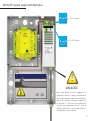
Status Lights
Green This LED is on when the input supply is healthy.
Red This LED is on when the input supply has failed - Power is being supplied by the battery.

13 14
INPUT AC 100-240V
50 / 60 Hz
1.2A
OUTPUT DC 13.8V 2A
V21
V0
V21
V0
V21
V0
USP
V0
12V 7Ah
INPUT AC 100-240V
50 / 60 Hz
1.2A
OUTPUT DC 13.8V 2A
0V
Net2 plus
0V
0V
0V
0V
0V
PSU
OK
0V
0V
ARM
SENSE
N.C.
N.O
1
2
COM
N.C.
N.O
COM
Data/D0
Clock/D1
CAT5
RS485
Media
Detect
0V
10
TX RX
100
Data/D0
Clock/D1
Media
Detect
10/100 Ethernet
N.C.
N.O
COM
12V - 24V
12V
1
2
12V
LED
LED
LED
12V
LED
LED
LED
LED
EXIT
EXIT
PSU
12V DC
12V DC
I
V21
V0
V21
V0
V42
V0
USP
V0
12V 7Ah
Ratings label

15
12V dc
Red LED
Amber LED
Green LED
Data/D0
Clock/D1
Media Detect
Entry
0V
Access Power
Entry Confirm (opt)
12V dc
Red LED
Amber LED
Green LED
Data/D0
Clock/D1
Media Detect
Entry
0V
Control Unit
Reader
0V
Exit/Entry
Green LED
12V dc
Hands Free Interface
12V
=
+
24V
!
r
e
da
e
R
:n
o
itu
a
C ylnos
r
eda
e
rC D
V2
1
r
o
F
12V
Red LED
Amber LED
Green LED
Data/D0
Clock/D1
Media Detect
0V
Entry
12V
12V Lock
0V
0V
N.C.
N.O.
COM
Alarm
12V
Green LED
Exit
0V
Contact
0V
0V
Tamper
PSU
0V
nottu BtixE
yaleR
kcoL
stuptuO
stupnI
rewoP
tcatnoC
repmaT/USP
Net2 nano
V21
V0
V21
V0
V42
V0
USP
V0
12V 7Ah
http://paxton.info/107
123456
0889
net2
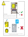
SAFETY WARNING
RISK OF EXPLOSION IF BATTERY IS REPLACED BY AN INCORRECT TYPE.
DISPOSE OF USED BATTERIES ACCORDING TO THE INSTRUCTIONS.
A Net2 nano ACU or a Hands free interface cannot be installed in the Metal cabinet as this would block the
RF signal used for the Net2Air wireless technology.

15 16
Input supply
voltage
Load output
current/power
(PoE+ High power)
Operating
Temperature
Moisture
Resistance
Load output
current/power
(PoE+)
Carrier frequency
0°C - +49°C
32°F - +120°F
802.3at
682-493
682-528
682-810
682-721
857-381
857-593
857-387
857-346
≤0.8A / ≤10.36W
≤0.8A / ≤10.36W
≤0.8A / ≤10.36W
N/A
N/A N/A
N/A
N/A
N/A
N/A
N/A N/A
N/A N/A
N/A N/A
N/A N/A
N/A
N/A
N/A
≤1.5A / ≤20.4W
≤1.5A / ≤20.4W
≤1.5A / ≥20.4W
24V AC
24V AC
50/60Hz
50/60HZ
N/A
N/A
24V AC
50/60HZ
0°C - +55°C
32°F - +131°F
0°C - +55°C
32°F - +131°F
Specications

17
1 - RS485 Data line resistance check - ACU not responding or fails to be detected.
First power down any data line converters and disconnect any ACU’s that do not have a ashing OK LED. Using a Multimeter, measure
the resistance across the White/Green and Green pair at one end of the network. A resistance of between 60 and 80 ohms is required.
Repeat the test for the White/Orange and Orange pair. This is vital for a stable and trouble free installation.
2 - ACU Reset - No OK LED ashing.
The ACU has no factory reset condition as it does not contain any xed settings. The unit does have an operating program (rmware)
that controls its functions and can be conrmed as running by means of the ashing OK LED.
• If the OK LED is ashing steadily, then there should be no reason to reset the unit.
• If the OK LED is not ashing, you need to clear the unit so that it can receive a rmware download from the PC. Any other ACU’s
without OK LED’s must be taken o the line or powered down.
1. Stop Net2 Server (Net2 server icon - Bottom right of screen - Right mouse click, Select Stop the Net2 Server).
2. Power down the Net2 ACU.
3. Insert a link wire between the ‘Amber LED’ and ‘Media Detect’ terminals on reader 2 port.
4. Power up the ACU. - The OK LED ashes very quickly.
5. With the unit still powered, remove the link.
6. Go to the PC and Start the Net2 Server and go into the Doors screen. Click on the Detect button. This should look for the ACU
and then download its rmware (This may take up to 5 minutes). - The OK LED should now be ashing with a steady heartbeat. This
procedure must only be done for one ACU at a time.
NOTE: If this unit is using the TCP/IP interface, any xed IP settings will be retained. If the unit is in DHCP mode it will need to be detected
at each stage using the Server Cong Utility as a new address may be issued by the IP server, each time the PCB resets.
3 - Can we use a DHCP IP address?
The Ethernet interface does support DHCP, but for more reliable communication, a static IP address must be reserved for the unit. This is
because some servers issue dierent DHCP addresses each time they are restarted and this requires the Net2 interface to be manually
set up again - a time consuming process.
4 - TCP/IP - Direct PC connection.
Connect the network interface directly to the LAN port of the PC. Without the presence of a DHCP server the unit will default to an IP
address in the range 169.254.X.X.
Check the IP address of the network card of your PC by typing IPCONFIG at the command prompt. Detect theTCP/IP interface through
the Net2 Conguration Utility and change the IP address of the interface to an addresssimilar to that of your machine. For example, if
the IP address of the PC is 192.168.10.7, change the IP address of the TCP/IP interface to 192.168.10.8. Once the IP address of theinterface
has been changed into the range of the PC then Net2 will be able to communicate with it.
NOTE: Do not change the IP address of your PC to 169.254.x.x, this will not allow the IP address of the TCP/IP
interface to be xed correctly.
Technical help

17 18
5 - Cannot detect ACU via a TCP/IP interface.
1. Ensure the TCP/IP interface has been detected in the Net2 Conguration Utility, and responds when PINGed
from the utility. A static IP address must be used for the interface.
2. If the interface is responding, try a loopback test. (see Loopback section)
3. The Net2 data line should be checked for resistance readings.
6 - Readers/Keypads not working.
• Software settings - Conrm that the settings of the reader or keypad are correct.
• Connections - Check the wiring and integrity of the connectors. - If possible, test this reader on the other port.
• Cable - Belden 9540 or 9538 should be used to extend the reader cable. Twisted pair alarm cable should not be used. To conrm
that a cable extension is not at fault, wire the reader direct into the reader port.
• Supply voltage - Conrm that the voltage is within specication. (see table)
• User token - Conrm that the user token used for testing is OK by presenting it to a known working reader.
• Interference - Conrm whether the reader works when tested ‘in hand’ and not mounted on the wall. Ensure
• that readers are not mounted back to back or there is no interference from other local RF devices.

19
+27 (0) 21 4276691
support@paxtonaccess.co.za
paxton.support
+31 (0)76 3333 999
paxton.benelux.support
support@paxton-benelux.com
+44 (0)1273 811011
paxton.support
support@paxton.co.uk
+49 (0) 251 2080 6900
paxton.gmbh.support
+44 (0)1273 811011
paxton.support
support@paxton.co.uk
8000 3570 3783
paxton.support
support@paxtonaccess.ae
+33 (0)1 57 32 93 56
support@paxtonaccess.fr
paxton.support
877.438.7298
usapaxton.support
supportUS@paxton-access.com
+52 55 5351 3667
paxton.soporte
+57 1508 8198
paxton.soporte
+32 (0) 78485147
paxton.benelux.support
support@paxton-benelux.com
La page est en cours de chargement...
La page est en cours de chargement...
La page est en cours de chargement...
La page est en cours de chargement...
-
 1
1
-
 2
2
-
 3
3
-
 4
4
-
 5
5
-
 6
6
-
 7
7
-
 8
8
-
 9
9
-
 10
10
-
 11
11
-
 12
12
-
 13
13
-
 14
14
-
 15
15
-
 16
16
-
 17
17
-
 18
18
-
 19
19
-
 20
20
-
 21
21
-
 22
22
-
 23
23
-
 24
24


dans d''autres langues
Documents connexes
-
Paxton ins-20006 Mode d'emploi
-
-
-
-
-
-
-
-
-
Autres documents
-
Dormakaba B-PSEBH Manuel utilisateur
-
 DMP 277 Trouble Annunciator Guide d'installation
-
Anviz SC011 Guide de démarrage rapide
-
 Digital Monitoring Products X1 SERIES SINGLE-DOOR AND MULTI-DOOR ACCESS CONTROLLER Compliance Guide
-
Samsung SSA-P400T Manuel utilisateur
-
Legrand Lighting Integrator DL Card Guide d'installation
-
Velleman HAA2801 Guide d'installation
-
ALLEGION SM10 Installation Instructions & User Manual
-
Bosch B308 Guide d'installation
-
Pyronix Deltabell E Guide d'installation

