DMP Electronics 1128 Guide d'installation
- Taper
- Guide d'installation

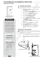
DESCRIPTION
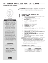
Figure 1: 1128 Wireless
Glassbreak Detector
1
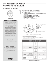
PROGRAM THE PANEL
When programming the 1128 in the panel, refer to the panel
programming guide as needed.
1. At a keypad, enter 6653 (PROG) to access the
PROGRAMMER menu.
2. Press CMD until ZONE INFORMATION displays and
press a top row select key or area.
3. Enter the wireless ZONE NO and press CMD.
4. Enter the ZONE NAME and press CMD.
5. Select NT (night) the ZONE TYPE.
6. Select the AREA NO and press CMD.
7. At the NEXT ZN? prompt, select NO and press CMD
until WIRELESS? displays.
8. Select YES when WIRELESS? displays and press
CMD.
9. Enter the eight-digit SERIAL# and press CMD.
10. Enter the SUPRVSN TIME and press CMD.
11. At the NEXT ZN? prompt, select YES if you are
finished programming the zone. Select NO if you
would like to access additional programming
options.
2
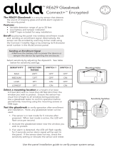
INSTALL THE BATTERY
Keep in mind, when setting up a wireless system, program
zones and connect the receiver before installing the included
CR123A battery in the transmitter.
1. Remove the holding screw at the lower end of the
1128 case and gently lift o the cover. See Figure 2.
2. Observing polarity, place the battery in the holder
and press into place. See Figure 3 for the battery
location.
The 1128 Wireless Glassbreak
Detector is a fully-supervised,
low current shock and
glassbreak sensor that
provides detection coverage
up to 20 ft from framed glass
mounted in an outside wall.
You can mount the 1128 on
the ceiling or on an opposing
wall for maximum flexibility
and coverage. The 1128
operates using the supplied
3 V lithium battery.
Compatibility
All DMP 1100 Series
Wireless Receivers and
Burglary Panels.
What is Included?
• One 1128 Wireless
Glassbreak Detector
• One 3 V lithium
CR123A battery
• Hardware Pack
Figure 2: Open the 1128
Figure 3: 1128 Battery Location
LED
Holding
Screw
Tamper
Battery
Holder
FIELD TEST
1128 WIRELESS GLASSBREAK DETECTOR
Installation Guide

2 1128 INSTALLATION GUIDE | DIGITAL MONITORING PRODUCTS
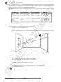
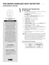
The 1128's 360° detection coverage is measured from the 1128 to the point on the glass farthest from
the 1128. Refer to the table below to determine the best location to place the 1128 based on window
type, glass thickness, window to wall range, and wall type.
Note: The sensor can be mounted as close as 3.3' (1 m) from the glass and the minimum glass
size is 1' x 2' (0.3 m x 0.6 m).
3
SELECT A LOCATION
Window Type Glass Thickness Maximum Range Wall Type
Plate 3/32" - 1/4" (2.4mm - 6.4mm) 20' (6m) Opposite, adjoining, ceiling
Tempered 1/8" - 1/4" (3.2mm - 6.4mm) 20' (6m) Opposite, adjoining, ceiling
Laminated 1/8" - 1/4" (3.2mm - 6.4mm) 20' (6m) Opposite, adjoining, ceiling
Wired 1/4" (6.4mm) 20' (6m) Opposite, adjoining, ceiling
Armor-coated N/A 12' (3.65m) Opposite, adjoining, ceiling
Optimize Detection
To optimize detection, install the 1128 in the following areas:
• Large rooms with moderate noise
• In the direct line of site of all windows that are to be protected
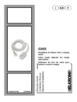
• On the opposite wall of the window that it's protecting. See Figure 4 for detection range.
20 ft (6m)
20 ft (6m)
Figure 4: 1128 Detection Range
Avoid False Alarms
To avoid false alarms, do not install the 1128 in the following areas:
• Rooms with lined, insulated, or dampening drapes
• Rooms with closed, wooden shutters on the inside
• Room corners
• Where white noise (air compressor) is present
• Rooms smaller than 10'x10'
• Rooms with multiple noise sources like televisions, sinks, speakers, etc.
• Excessively humid rooms
Note: Avoid programming the 1128 as a day or supervisory zone to help avoid false alarms.
FIELD TEST

1128 INSTALLATION GUIDE | DIGITAL MONITORING PRODUCTS 3
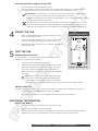
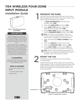
1. With the 1128 already open, place the 1128 base on the
wall in the desired location.
2. Use the provided hardware pack to mount the base to
the wall. See Figure 5 for mounting hole locations.
3. Reinstall the 1128 cover back on to the base and tighten
the holding screw.
4
MOUNT THE 1128
5
TEST THE 1128
Handheld Glassbreak Test
To test the 1128, use a hand-held tester like the DMP Model
5709C-W to imitate glass breaking.
1. Set the tester to tempered glass mode.
2. Stand near the protected glass and activate the tester.
When the 1128 red LED momentarily lights solid red,
the glass is within the detection range. Repeat this
step for all detection areas in order to ensure adequate
coverage.
Note: Room acoustics can artificially extend the
1128's sensor range. The 1128's specified range is
established for worst-case conditions. While the
1128 may function at an additional range, it may miss a minimum output break.
Wireless Walk Test
Perform a Wireless Walk Test to confirm that the 1128 is communicating clearly with the panel.
1. At the keypad, enter 8144 (WALK) and select WLS.
2. If the 1128 fails to check in at the keypad, relocate the 1128 or the receiver.
MOUNTING HOLES
Figure 5: Mounting Holes
Replace the Battery
1. Remove the holding screw and open the 1128 housing.
2. Remove the old battery from the holder.
3. Observe polarity and insert the new battery in the holder (3 V lithium CR123A battery).
4. Replace the cover on the 1128 and secure the housing with the holding screw.
ADDITIONAL INFORMATION
FIELD TEST
Check the Location Using the Survey LED
1. Hold the 1128 in the exact desired location.
2. Press the tamper switch to send data to the receiver and determine if communication is
confirmed or faulty. See Figures 2 and 3 for tamper switch and LED locations.
Confirmed: If communication is confirmed, the survey LED turns on when data is
sent to the receiver and o when acknowledgement is received.
Faulty: If communication is faulty, the LED remains on for several seconds or flashes
multiple times in quick succession.
Relocate the 1128 or receiver until the LED confirms clear communication. Proper
communication between the 1128 and receiver is verified when for each press or
release of the tamper switch, the LED blinks immediately on and immediately o.

INTRUSION • FIRE • ACCESS • NETWORKS
2500 North Partnership Boulevard
Springfield, Missouri 65803-8877
866.266.2826 | DMP.com
© 2018 Digital Monitoring Products, Inc.
LT-1825 18365
Specifications
Battery
Life Expectancy 3 Years (normal operation)
Type 3 V lithium CR123A
Frequency Range 905-925 MHz
Transmit Condition Alarm, Low Battery, Tamper
Detection Method Omni-directional
Range 20 ft (6 m)
Operating Temperature -10°C to +55°C
Current Standby
Color White (passes VW1)
Housing Material Flame retardant ABS
Dimensions 3.3"L x 2.1"W x 0.9"D
Weight 4.2 oz.
Certifications
FCC Part 15 Registration ID CCK1128
IC Registration ID 5251A-1128
Accessories
5709C-W Glassbreak Simulator
FCC INFORMATION
This device complies with Part 15 of the FCC Rules. Operation is subject to the following two conditions:
1. This device may not cause harmful interference, and
2. This device must accept any interference received, including interference that may cause undesired operation.
The antenna used for this transmitter must be installed to provide a separation distance of at least 20 cm (7.874 in.) from all
persons. It must not be located or operated in conjunction with any other antenna or transmitter.
Changes or modifications made by the user and not expressly approved by the party responsible for compliance could void the
user’s authority to operate the equipment.
Note: This equipment has been tested and found to comply with the limits for a Class B digital device, pursuant to
part 15 of the FCC Rules. These limits are designed to provide reasonable protection against harmful interference in a
residential installation. This equipment generates, uses and can radiate radio frequency energy and, if not installed and
used in accordance with the instructions, may cause harmful interference to radio communications. However, there is no
guarantee that interference will not occur in a particular installation. If this equipment does cause harmful interference to
radio or television reception, which can be determined by turning the equipment o and on, the user is encouraged to try
to correct the interference by one or more of the following measures:
• Reorient or relocate the receiving antenna.
• Increase the separation between the equipment and receiver.
• Connect the equipment into an outlet on a circuit dierent from that to which the receiver is connected.
• Consult the dealer or an experienced radio/TV technician for help.
INDUSTRY CANADA INFORMATION
This device complies with Industry Canada Licence-exempt RSS standard(s). Operation is subject to the following two conditions:
1. This device may not cause interference, and
2. this device must accept any interference, including interference that may cause undesired operation of the device.
Le présent appareil est conforme aux CNR d’Industrie Canada applicables aux appareils radio exempts de licence. L’exploitation
est autorisée aux deux conditions suivantes:
1. l’appareil ne doit pas produire de brouillage, et
2. l’utilisateur de l’appareil doit accepter tout brouillage radioélectrique subi, même si le brouillage est susceptible d’en
compromettre le fonctionnement.
This system has been evaluated for RF Exposure per RSS-102 and is in compliance with the limits specified by Health Canada
Safety Code 6. The system must be installed at a minimum separation distance from the antenna to a general bystander of 7.87
inches (20 cm) to maintain compliance with the General Population limits.
L’exposition aux radiofréquences de ce système a été évaluée selon la norme RSS-102 et est jugée conforme aux limites établies
par le Code de sécurité 6 de Santé Canada. Le système doit être installé à une distance minimale de 7.87 pouces (20 cm) séparant
l’antenne d’une personne présente en conformité avec les limites permises d’exposition du grand public.
FIELD TEST
1128 WIRELESS GLASSBREAK
DETECTOR
-
 1
1
-
 2
2
-
 3
3
-
 4
4


DMP Electronics 1128 Guide d'installation
- Taper
- Guide d'installation
dans d''autres langues
Documents connexes
Autres documents
-
AJAX 9NA HomeSiren Mode d'emploi
-
AJAX 9NA MotionProtect Plus Pet Immune Motion Detector Mode d'emploi
-
 Digital Monitoring Products 1126 Guide d'installation
-
 DMP 1183 Series Wireless Heat Detector Guide d'installation
-
AJAX AJ-MOTIONCAM-W Manuel utilisateur
-
 Alula RE629 Guide d'installation
-
 Elkron GD03 Manuel utilisateur
-
Gemini Headphones UZ-1128 Manuel utilisateur
-
ADEMCO Ademco 5802WXT Guide d'installation
-
Aastra IntelliGate 630d Quick User Manual


