
FROG-CD
FROG-CS
www.came.com
n
o
p
q
r
s
t
u
447,5
350
195
580
100
64
720
570
~ 850
~ 1000
600
1000
1100
FROG-CS
FROG-CD FROG-CS
FROG-CD
24h
100
Italiano
IT
IT
English
EN
EN
Français
FR
FR
Русский
RU
RU
FA00610M4A - ver.
1
1 - 10/2016
FA00610M4A

FA00610M4A - ver.
1
1 - 10/2016
ITALIANO
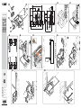
Descrizione
Cassa di fondazione destra o sinistra in acciaio con trattamento in cataforesi,
completa di leva di aggancio sblocco, staffa di fissaggio al cancello e fermo
meccanico.
Componenti
1. Braccio superiore
2. Gruppo bracci
3. Bronzina
4. Copriforo
5. Fermo meccanico
6. Cassa
7. Coperchio
8. Tappo
Installazione
Le seguenti illustrazioni sono solo esempi, in quanto lo spazio per il
fissaggio dell’automazione e degli accessori varia a seconda degli ingombri.
Spetta quindi all’installatore scegliere la soluzione più adatta.
Usare delle attrezzature di sollevamento per trasportare e posizionare la
cassa di fondazione
Le figure che seguono si riferiscono a una installazione standard di un
cancello con apertura verso l’interno.
- Fare lo scavo per la cassa.
- Preparare le scatole di derivazione e tubi corrugati necessari per i
collegamenti al pozzetto di derivazione e per il tubo per il drenaggio.
Il numero di tubi dipende dal tipo di impianto e dagli accessori previsti.
- Prima di posizionare la cassa, scegliere il verso di apertura dell’anta:
apertura verso l'interno, apertura verso l'esterno.
- Posizionare la cassa addossata al pilastro facendo attenzione che i tubi
corrugati e quello per il drenaggio passino attraverso i fori predisposti.
- Riempire lo scavo con del calcestruzzo.
- Livellare la cassa al suolo e posizionare il perno in asse con il cardine
superiore del cancello. Lasciare solidificare per almeno 24 ore.
Pulire l’interno della cassa dai residui di calcestruzzo.
- Lubrificare il perno della cassa, la bronzina , il gruppo bracci e
il braccio superiore . Assemblare il tutto come da disegno.
- Montare l’anta del cancello inserendo il cardine superiore. Verificare che
l’anta si apra e si chiuda senza difficoltà. Fissare con viti adeguate o saldare
accuratamente l’anta al braccio superiore.
- Appoggiare il coperchio sopra la cassa di fondazione, fissare il copriforo
e inserire il tappo sul coperchio.
DISMISSIONE E SMALTIMENTO - I componenti dell’imballo (cartone, plastica, etc.)
sono assimilabili ai rifi uti solidi urbani. I componenti del prodotto (metalli, schede elet-
troniche, batterie,etc.) vanno separati e di erenziati. Per le modalità di smaltimento
verifi care le regole vigenti nel luogo d’installazione.
NON DISPERDERE NELL’AMBIENTE!
I CONTENUTI DEL MANUALE SONO DA RITENERSI SUSCETTIBILI DI MODIFICA IN
QUALSIASI MOMENTO SENZA OBBLIGO DI PREAVVISO.
LE MISURE, SE NON DIVERSAMENTE INDICATO, SONO IN MILLIMETRI.
ENGLISH
Description
Left or right steel cataphoresis-treated foundation-casing, complete with
release latching-lever, gate-fastening brace and mechanical stop.
Components
1. Upper arm
2. Arms assembly
3. Bushing
4. Hole cover
5. Mechanical stop
6. Casing
7. Cover
8. Cap
Installation
The following illustrations are mere examples in that the space for fastening
the operator and accessories varies depending on the installation area. It is up
to the fitter, therefore, to choose the most suitable solution.
Use proper hoisting gear to transport and position the foundation casing
The following illustrations show a standard installation for an inner-opening
gate.
- Dig the box pit.
- Set up the junction box and corrugated conduits needed for connecting
up to the junction pit and for the drainage tube.
The number of tubes depends on the type of system and the
accessories you are going to fit.
- Before positioning the casing, decide in which direction the gate-leaf will
open: inwards opening, outwards opening.
- Position the casing up against the post. Make sure the corrugated conduits
and the drainage tube run through their corresponding holes.
- Fill the hole with concrete.
- Level the box with the ground and fit the pin along the same axis as that
of the gate’s upper hinge. Let set for at least 24 hours.
Clean the inside of the casing from any residual concrete.
- Lubricate the casing-pin, the bushing , the arms assembly and
the upper arm . Assemble everything as shown in the drawing.
- Fit the gate leaf by fitting the upper hinge. Check that the gate leaf opens
and closes smoothly. Use suitable screws or soundly weld the gate leaf to
the upper arm.
- Rest the cover onto the foundation casing, fasten the hole-plug and fit
the cap onto the cover.
FRANÇAIS
Description
Caisse de fondation droite ou gauche en acier traité par cataphorèse, avec
levier de fixation du dispositif de déblocage, étrier de fixation au portail et butée
mécanique.
Composants
1. Bras supérieur
2. Groupe bras
3. Coussinet
4. Cache-trou
5. Butée mécanique
6. Caisse
7. Couvercle
8. Capuchon
Installation
Les illustrations suivantes ne sont que des exemples étant donné que
l’espace pour la fixation de l’automatisme et des accessoires varie en fonction
des encombrements. C’est donc l’installateur qui doit choisir la solution la plus
indiquée.
Utiliser des moyens de levage pour transporter et positionner la caisse de
fondation.
Les figures suivantes se réfèrent à l’installation standard d’un portail
s’ouvrant vers l’intérieur.
- Creuser la fosse pour la caisse.
- Préparer les boîtiers de dérivation et les gaines annelées nécessaires
pour les raccordements et pour le drainage.
Le nombre de gaines dépend du type d’installation et des accessoires
prévus.
- Avant de positionner la caisse, choisir le sens d’ouverture du vantail :
ouverture vers l’intérieur, ouverture vers l’extérieur.
- Positionner la caisse contre le pilier en s’assurant que les gaines annelées
et le tuyau de vidange passent bien à travers les trous prévus à cet effet.
- Remplir la fosse de béton.
- Niveler la caisse par rapport au sol et positionner le pivot en l’alignant
avec la charnière supérieure du portail. Laisser solidifier pendant au moins
24 heures.
Éliminer tout résidu de béton à l’intérieur de la caisse.
- Lubrifier le pivot de la caisse, le coussinet , le groupe de bras
et le bras supérieur . Assembler le tout comme indiqué sur le dessin.
- Monter le vantail du portail sur la charnière supérieure. S’assurer que le
vantail s’ouvre et se ferme facilement. Fixer à l’aide de vis appropriées, ou
souder soigneusement, le vantail au bras supérieur.
- Poser le couvercle sur la caisse de fondation, fixer le cache-trou et
appliquer le capuchon sur le couvercle.
РУССКИЙ
Описание
Монтажный корпус для правого или левого привода, выполненный из стали
с антикоррозионной обработкой методом катафореза, укомплектованный
нижним рычагом с креплением механизма для разблокировки, верхним
рычагом, монтируемым на створку, и механическим упором.
Компоненты
1. Верхний рычаг
2. Рычажный узел
3. Бронзовая втулка
4. Вставка для отверстия
5. Механический упор
6. Монтажный корпус
7. Крышка монтажного корпуса
8. Заглушка
Монтаж
Приведенные ниже рисунки носят иллюстративный характер, так как
пространство для установки автоматики и дополнительных принадлежностей
может меняться от случая к случаю. Таким образом, выбор оптимального
решения должен осуществляться монтажником на месте.
Для перемещения монтажного основания используйте необходимые
грузоподъемные приспособления.
Представленные ниже рисунки иллюстрируют типовой монтаж распашных
ворот с открыванием вовнутрь.
- Произведите выемку грунта под монтажное основание.
- Подготовьте разветвительные коробки и гофрированные трубы,
необходимые для электрических соединений с разветвительным колодцем
и системой дренажа.
Количество гофрошлангов зависит от варианта автоматической
системы и предусмотренных дополнительных устройств.
- Перед установкой монтажного основания выберите направление
открывания створки: открывание вовнутрь, открывание наружу.
- Поместите основание корпуса в яму вплотную к столбу, обращая особое
внимание на то, чтобы дренажная и гофрированные трубы выходили из
специально предусмотренных для этого отверстий.
- Залейте яму раствором. .
- Выровняйте верхний край монтажного корпуса относительно земли
и установите осевой стержень так, чтобы он располагался на одной
оси с верхней петлей ворот. Подождите не менее 24 часов, чтобы бетон
полностью затвердел.
Очистите внутреннюю часть от остатков бетона.
- Смажьте стержень монтажного основания, бронзовую втулку ,
рычажный узел и верхний рычаг . Установите всё так, как показано на
рисунке.
- Установите створку сверху на петлю ворот, а снизу на верхний
рычаг. Проверьте, чтобы створка свободно открывалась и закрывалась.
Зафиксируйте с помощью надлежащих винтов или осторожно приварите
створку к верхнему рычагу.
- Установите крышку поверх монтажного корпуса, установите вставку для
отверстия и вставьте заглушку в крышку.
DISMANTLING AND DISPOSAL -
The packaging materials (cardboard, plastic, and so on)
should be disposed of as solid household waste. The product components (metals;
electronic boards, batteries, etc.) must be separated from other waste for recycling.
Check your local laws to properly dispose of the materials.
DO NOT DISPOSE OF IN NATURE!
THE CONTENTS OF THIS MANUAL MAY CHANGE, AT ANY TIME, AND WITHOUT
NOTICE.
MEASUREMENTS, UNLESS OTHERWISE INDICATED, ARE IN MILLIMETRES.
MISE AU REBUT ET ÉLIMINATION - Les composants de l’emballage (carton,
plastique, etc.) sont assimilables aux déchets urbains solides. Les composants du
produit (métal, cartes électroniques, batteries, etc.) doivent être triés et di érenciés.
Pour les modalités d’élimination, vérifi er les normes en vigueur sur le lieu d’installation.
NE PAS JETER DANS LA NATURE !
LE CONTENU DE CE MANUEL EST SUSCEPTIBLE DE SUBIR DES MODIFICATIONS À
TOUT MOMENT ET SANS AUCUN PRÉAVIS.
LES DIMENSIONS SONT EXPRIMÉES EN MILLIMÈTRES, SAUF INDICATION
CONTRAIRE.
УТИЛИЗАЦИЯ — Упаковочные материалы (картон, пластмасса и т. д.) могут быть
утилизированы как бытовые отходы. Материалы и компоненты изделия (металл,
электронные платы, элементы питания и т.д.) необходимо разделить перед утилизацией.
Утилизацию изделия необходимо проводить в соответствии с действующим
законодательством местности, в которой производилась его эксплуатация.
НЕ ЗАГРЯЗНЯЙТЕ ОКРУЖАЮЩУЮ СРЕДУ!
ВСЕ ДАННЫЕ, СОДЕРЖАЩИЕСЯ В ЭТОЙ ИНСТРУКЦИИ, МОГУТ БЫТЬ ИЗМЕНЕНЫ В
ЛЮБОЕ ВРЕМЯ И БЕЗ ПРЕДВАРИТЕЛЬНОГО УВЕДОМЛЕНИЯ.
ВСЕ РАЗМЕРЫ ПРИВЕДЕНЫ В МИЛЛИМЕТРАХ, ЕСЛИ НЕ УКАЗАНО ИНОЕ.
-
 1
1
-
 2
2


dans d''autres langues
- italiano: CAME FROG-CD/CS Guida d'installazione
Documents connexes
-
CAME FROG-CF/CFI Guide d'installation
-
-
-
CAME FROG-AV Guide d'installation
-
-
-
CAME FA70230CB Guide d'installation
-
CAME FROG A Guide d'installation
-
CAME FE40230 Guide d'installation
-