ROSIERES RTG 64 Le manuel du propriétaire
- Taper
- Le manuel du propriétaire

HOBS
USER INSTRUCTIONS
GB - IE
CANDY HOOVER GROUP S.R.L. • Via Privata Eden Fumagalli • 20047 Brugherio Milano Italy
TABLES DE CUISSON
NOTICE D’EMPLOI
FR
ВАРОЧНЫЕ ПОВЕРХНОСТИ
ИНСТРУКЦИЯ ПОЛЬЗОВАТЕЛЯ
RU

CONTENT
1. Instructions For The Installer
1.1. Bulding In
1.2. Suitable Location
2. Electrical Connection (For U.K. Only)
2.1. Electrical Connection
2.2. Gas Connection (For U.K. Only)
2.3. Adapting The Hob To Different Types Of Gas
2.4. Regulating The Minimum Flame
3. Use Of Hob - User Instructions
3.1. Using The Gas Burner
4. Maintenance and Cleaning
5. Aftercare
6. Protection Of The Environment
GB - IE
.........................................................................................................................................................................07
.......................................................................................................................................................................................................07
...........................................................................................................................................................................................07
...........................................................................................................................................................07
.....................................................................................................................................................................................07
.....................................................................................................................................................................07
.................................................................................................................................................08
.....................................................................................................................................................................08
......................................................................................................................................................................08
....................................................................................................................................................................................08
.............................................................................................................................................................................09
...........................................................................................................................................................................................................09
......................................................................................................................................................................09
CONTENU
1.
1.1 Encastrement
1.2.
2.1.
2.2.
2.3.
2.4.
3.1. Using The Gas Burner
Installation
Caracteristiques Requises
Raccordement Electrique
Raccordement Gaz
Adapter La Table A Differents Types De Gaz
Reguler La Flamme Au Minimum
3. Utilisation De La Table
4. Maintenance Et Entretien
5. Assistance Technique
6. Protection De L'environnement
FR
.......................................................................................................................................................................................................04
..................................................................................................................................................................................................04
..............................................................................................................................................................................04
...............................................................................................................................................................................04
.........................................................................................................................................................................................04
.................................................................................................................................................05
...................................................................................................................................................................05
....................................................................................................................................................................................05
....................................................................................................................................................................................05
...............................................................................................................................................................................06
.....................................................................................................................................................................................06
.....................................................................................................................................................................06
СОДЕРЖАНИЕ
1. Инструкции по выполнению установки
1.1. Встраиваемые варочные поверхности
1.2. Выбор места для установки варочной поверхности
2. Подключение к электросети (только для Великобритании)
2.1. Подключение к электросети
2.2. Подключение к линии газоснабжения (только для Великобритании)
2.3. Адаптация варочной поверхности на другие типы газа
2.4. Регулировка минимального пламени
3. Инструкции по эксплуатации варочной поверхности
3.1 использование
газовой конфорки
4. Обслуживание и чистка
5. Послепродажное обслуживание
6. Защита окружающей среды
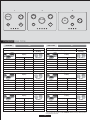
Gas Type Tables
RU
....................................................................................................................................................10
........................................................................................................................................................10
..................................................................................................................................10
..................................................................................................................10
.........................................................................................................................................................................10
.......................................................................................................10
.............................................................................................................................11
..........................................................................................................................................................11
.............................................................................................................................11
.................................................................................................................................................................11
................................................................................................................................................................................12
.................................................................................................................................................................12
........................................................................................................................................................................12
.........................................................................................................................................................................................13-14-15

03 GB - IE
accessible space
Figure 3
Min 10 mm
Sp.da 25 a 45 mm
Figure 2Figure 1
2
60 cm
2
240 cm
2
120 cm
2
180 cm
Figure 5Figure 4
1/2 GAS
CONICAL
C
AB
CYLINDRICAL
CONICAL
INJECTOR
Figure 6
Figure 7
Figure 8 Figure 9
Plan 60
Plan 75

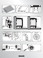
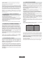
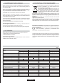
1. INSTALLATION
Le meuble ou le support dans lequel doit être encastrée la table, ainsi
que les parois du meuble qui pourraient juxtaposer celui-ci, doivent
être d'une matière résistant à une température élevée (jusqu'à 100°C)
et d'une épaisseur comprise entre 25 et 45 cm.
Les dimensions d'encastrement sont indiquées sur le schéma 2
.
Si la table est installée entre deux meubles de cuisine, la distance
entre la table et les meubles doit être au moins de 15 cm (voir schéma
4); tandis que la distance entre la table et le mur du fond doit être au
moins de 5,5 cm. La distance entre
la table et tout autre appareil ou
meuble situé au dessus (par exemple une hotte) doit être au moins de
70 cm (voir schéma 4).
300 cm²
Si, en fonction de l'installation de la table, la partie inférieure de son
caisson se trouve à proximité d'une zone normalement accessible
lors
de manipulations et/ou de rangements, placer une cloison (bois
ou similaire) pour éviter tous risques de brûlure ou de détérioration
(schéma 3).
Attention : Lors de la mise en place, un soin particulier doit être
porté au joint entourant le bord de la table afin d'éviter toute
infiltration dans
le meuble support (schéma 1).
Lors de la mise en place du joint sur la partie arrière, veiller à ne pas
obstruer les passages d'air nécessaires à la combustion.
Le caisson de la table est équipé en dessous de 4 emplacements
prévus pour recevoir les brides de fixation destinées à l'immobilisation
de la table sur le meuble. Placer les 4 brides de fixation de manière à
ce que la table de travail soit parfaitement plaquée au meuble.
Si une table de 60 cm de large est installée au-dessus d'un four qui
n'est pas équipé de ventilation tangentielle, il est recommandé de
créer
des ouvertures dans le caisson de cuisine pour faire ainsi
circuler l'air.
La taille de ces ouvertures doit être au moins de et placées
comme indiqué sur le schéma 5.
Si c'est une table de 75cm de large qui est installée au-dessus du four,
ce dernier doit être équipé d'une ventilation
tangentielle.
04 FR
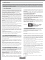
La mise en place fonctionnelle des appareils ménagers dans leur environnement est une opération délicate qui, si elle n'est pas correctement
effectuée, peut avoir de graves conséquences sur la sécurité des consommateurs. Dans ces conditions, il est impératif de confier cette tâche à
un professionnel qui la réalisera conformément aux normes
techniques en vigueur. Si malgré cette recommandation, le consommateur
réalisait lui-même l'installation, le constructeur déclinerait toute responsabilité en cas de défaillance technique du produit entraînant ou non
des dommages aux biens et/ou aux personnes.
1.1 ENCASTREMENT
1.2. CARACTERISTIQUES REQUISES
Un appareil de cuisson alimenté par le gaz produit de la chaleur et de
l'humidité à l'endroit où il est installé. Pour cette raison, veuillez
assurer la bonne ventilation de la pièce en gardant des courants d'air
ou en installant une hotte.
Une utilisation intensive et prolongée de l'appareil peut requérir
une
ventilation plus importante, telle que l'ouverture d'une fenêtre ou une
puissance d'aspiration plus intense de la VMC si vous en êtes
équipés.
S'il n'est pas possible d'installer une hotte, une VMC devrait être
installée sur un mur donnant sur l'extérieur ou sur une fenêtre.
La VMC devrait être en mesure
d'apporter un changement complet de
l'air de la cuisine 3 à 5 fois par heure. L'installateur doit installer la VMC
conformément aux règles en vigueur dans le pays d'installation
PHASE
TERRE
NEUTRE
L
N
Câble
lectrique
d’alim
é
Fil Marron
Fil Vert/jaune
Fil Bleu
Alimentation
2.2. RACCORDEMENT GAZ
L'appareil doit être installé et raccordé conformément aux règles
En vigueur dans le pays d'installa-tion. Une attention
particulière sera accordée aux dispositions applicables en matière
De ventilation.
Tous les travaux d'installation doivent être effectués avec l'électricité
déconnectée.
La plaque signalétique sur la plaque indique le type de gaz qui doit
être utilisé.
Le raccordement au réseau d'approvisionnement en gaz
cylindre doit être effectuée qu'après avoir vérifié qu'il est réglementé
pour le type de gaz avec lequel il sera distribué. S'il n'est pas
correctement réglementé, voir les instructions dans les paragraphes
suivants pour modifier les paramètres du gaz.
Pour le gaz liquide (bouteille de
gaz), utiliser des régulateurs de
pression conformes aux normes en vigueur.
Utilisez uniquement des tuyaux, des rondelles et des rondelles
d'étanchéité conformes aux normes en vigueur.
Pour certains modèles un lien conique est fourni pour installation
l'appareil, dans les pays où ce type de lien est obligatoire ; sur le
schéma 8,
il est indiqué comment reconnaître les différents types de
liens (CY = cylindrique, CO = conique). Dans tous les cas, la partie
cylindre du lien doit être connecté à la table.
Lorsque vous connectez la table de cuisson à l'alimentation du gaz via
l'utilisation de tuyaux flexibles, veuillez faire en sorte
que la distance
maximum couverte par le tuyau ne dépasse pas 2 mètres.
Pour éviter tout dommage potentiel à la table de cuisson, veuillez
effectuer l'installation suivant les indications du schéma 6.
1) Comme illustré dans le schéma, assembler les pièces en
séquence :
A: ½ Adaptateur Cylindrique mâle
B: ½ Obturation
C:
½ Adaptateur gaz Femelle conique-cylindrique ou cylindrique-
cylindrique
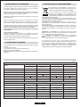
2.1. RACCORDEMENT ELECTRIQUE
"L'installation recevant l'appareil cité en référence doit être
conforme à la norme en vigueur dans le pays
d'installation". Le constructeur décline toute responsabilité
en cas de non respect de cette disposition.
Attention : vérifier la continuité de la terre de l'installation
avant de procéder au raccordement. Notre responsabilité ne
Vérifier les données sur la plaque signalétique, située à
l'extérieur de l'unité, pour assurer que l'alimentation et le
voltage conviennent.
Avant le branchement, vérifier le système de mise à la
terre.
saurait être engagée pour tout incident ou ses conséquences
éventuelles qui pourraient survenir à l'usage d'un appareil non
relié à la terre, ou relié à une terre dont la continuité serait
défectueuse.
Si une prise n'est pas déjà fournie, installer une prise appropriée pour
la charge indiquée sur la plaque signalétique.
La prise devrait toujours être accessible.
Le fil de terre
est de couleur jaune / vert.
Lorsque la table de cuisson est reliée directement à
l'approvisionnement en électricité, un disjoncteur doit être installé.
Si le cordon d'alimentation est endommagé, il doit être remplacé par
un technicien qualifié afin d'éviter tout risque potentiel.
Le fil de terre (couleur vert et jaune) doit être
au moins 10mm plus long
que les fils de phase et neutre.
La section du câble utilisé doit être de la bonne taille par rapport à la
puissance absorbée de la table de cuisson.
Veuillez vérifier la plaque signalétique pour les détails de puissance et
veiller à ce que le cordon
d'alimentation électrique soit de type
l'H05RR F, H05VV-F, F-H05V2V2.

2.3. ADAPTER LA TABLE A DIFFERENTS
TYPES DE GAZ
Pour adapter la table de cuisson à différents types de gaz, veuillez
exécuter les instructions suivantes:
• Enlever les grilles, chapeaux et corps de brûleurs
• Insérez une clé à pipe (7 mm) dans le support du brûleur (schéma 7)
• Dévisser le/les injecteurs et le/les remplacer par un/des injecteurs
adaptés
au gaz à utiliser (voir le type de gaz préconisé sur la table)
• Visser le/les injecteurs à fond
• Régler la bague d'air
• Replacer les corps de brûleurs, le chapeau de brûleur et les grilles
2) Serrer les joints avec des clés à molette, pensez à placer les
tuyaux en position.
3) Fixer le raccord C au réseau d'approvisionne-ment en gaz à
l'aide tuyau rigide ou en acier flexi-ble.
IMPORTANT: effectuer une dernière vérification pour détecter
les fuites sur les raccords de tuyauterie en utilisant une solution
savonneuse. Ne jamais utiliser une flamme. Aussi, assurez vous
que le tuyau flexible ne peut
pas entrer en contact avec une
partie mobile du meuble de cuisine (par exemple un tiroir) et qu'il
ne se trouve pas à un endroit où il pourrait être endommagé.
Attention: Si vous sentez des émanations de gaz en provenance de
l'appareil, coupez immédiatement l'alimentation en gaz et appelez
directement une
personne qualifiée. Ne cherchez pas une fuite à
l'aide d'une flamme.
2.4. REGULER LA FLAMME AU MINIMUM
Après l'allumage du brûleur, tourner le bouton de commande au
réglage minimum, puis enlever la manette de commande (ce qui
peut facilement être enlevé par appliquer une légère pression).
En utilisant un petit «Terminal » type tournevis, la vis de réglage peut
être ajustée (cf Schéma 9). En tournant la vis
dans le sens des
aiguilles d'une montre, cela réduit le débit de la flamme, alors qu'en
tournant dans le sens inverse, cela l'augmente. Utilisez ce réglage
pour obtenir une flamme d'environ 3 à 4 mm de longueur, puis
replacer la manette de commande.
Lorsque l'approvisionnement en gaz disponible est du
butane/propane
(gaz de bouteilles), la vis pour régler la flamme au
ralenti doit être tournée dans le sens des aiguilles d'une montre,
jusqu'à la butée.
Lorsque vous avez effectué la régulation du gaz, remplacer
l'ancienne plaque signalétique de votre appareil avec celle adaptée
au type de gaz installé (fournie avec plaque de
cuisson).
3.1. USING THE GAS BURNER
Pour allumer les brûleurs, placez une flamme (allume-feu, allumette,
briquet etc…) près du brûleur, appuyez et tournez la manette de
commande.
Si les brûleurs n'ont pas été utilisés depuis quelques jours, attendre
quelques secondes avant d'allumer le brûleur, ce qui permettra l'air
éventuellement présent dans les tuyaux de s'échapper.
Pour les appareils
équipés d'allumage électronique, effectuer les
opérations suivantes:
• Pousser et tourner la manette de commande sur le symbole
d'allumage.
• Allumer le brûleur en appuyant sur le bouton d'allumage
Pour les tables de cuisson équipées d'allumage électronique intégré,
il suffit de pousser et tourner le bouton sur le symbole d'allumage.
Le système
d'allumage continuera à produire des étincelles aussi
longtemps que le robinet de gaz est actionné.
Si le brûleur ne s'enflamme pas dans les 5 secondes, tournez le
bouton vers la position 0 et répéter l'opération.
Pour les modèles équipés d'un robinet de sécurité par thermocouple
(qui coupe l'écoulement du gaz si la
flamme est accidentellement
éteint), les brûleurs sont allumés et décrit ci-dessus, mais il faut
prendre soin de garder la manette de commandes enfoncée pendant
5 ou 6 secondes après que la flamme est allumée.
ATTENTION : Avant d'allumer la table gaz, veillez à ce que les
brûleurs et les chapeaux de
brûleur soient correctement placés dans
leur position.
CONSEIL
Pour de meilleurs résultats, la taille de casseroles à fond plat doit
correspondre à la taille des brûleurs comme suit :
Pour les petites casseroles/poêles, le brûleur à gaz doit être réglé de
telle manière que la flamme ne chevauche pas le fond de
la casserole.
Les récipients à fond concave ou convexe ne doivent pas être utilisés.
ATTENTION: Si un brûleur est accidentellement éteint, tournez le
bouton vers la position fermée et ne pas tenter de relancer
pendant au moins 1 minute.
Si au fil des années les robinets de gaz deviennent raides, il
est
nécessaire de les lubrifier.
Cette opération doit être effectuée que par un technicien agréé.
Type de brûleurs
Ø (cm)casserole
A
SR
R
UR
QC
12 - 18
18 - 24
24 - 26
24 - 28
24 - 28
Brûleur auxiliaire
Brûleur semi-rapide
Brûleur rapide
Brûleur ultra rapide
Brûleur quadruple
couronne
Table A
05 FR
3. UTILISATION DE LA TABLE
Cet appareil ne doit être utilisé que pour des fins pour lesquelles il est
destiné : la cuisson domestique. Toute autre utilisation sera
considérée comme abusive et peut donc être dangereuse. Le
fabricant ne sera pas responsable pour tout dommage ou perte
découlant d'une utilisation abusive.
Cet appareil n'est pas destiné
à être utilisé par des personnes (y
compris les enfants) dont les capacités physiques, sensorielles ou
mentales sont réduites, ou ayant un manque d'expérience et de
connaissances, à moins qu'elles n'aient été formées et encadrées
concernant l'utilisation de l'appareil par une personne responsable de
leur sécurité.
Les enfants doivent être surveillés
pour s'assurer qu'ils ne jouent pas
avec l'appareil.

4. MAINTENANCE ET ENTRETIEN
Avant de nettoyer la table de cuisson, assurez-vous que cet appareil
est refroidi. Retirez la fiche de la prise ou (s'il est connecté
directement), éteindre l'alimentation d'électricité.
Ne jamais utiliser de produits abrasifs, de détergents corrosifs, agents
de blanchiment ou d'acides. Éviter les substances acides ou alcalines
(citron, jus, vinaigre etc…)
sur l'émail ou l'acier.
ATTENTION - Ne pas utiliser de nettoyeurs à vapeur pour nettoyer les
plaques de cuisson.
Lors du nettoyage de l'émail, vernis ou des sections chromées,
utilisez de l'eau chaude savonneuse ou un détergent non corrosif.
Pour l'acier inoxydable, utilisez une solution de nettoyage appropriée.
Les brûleurs peuvent être
nettoyés avec de l'eau savonneuse. Pour
restaurer leur éclat d'origine, utilisez un nettoyant ménager pour acier
inoxydable. Après nettoyage, séchez les brûleurs et les replacer.
Il est important que les brûleurs soient remplacés correctement
à leur position.
Grilles chromées et brûleurs
Les grilles chromées et les brûleurs ont tendance à foncer à
l'utilisation. Il s'agit d'un phénomène normal et inévitable, mais elle ne
compromet pas la fonctionnalité de la table de cuisson.
Si besoin, des pièces de rechange sont disponibles dans notre centre
de service après-vente.
5. ASSISTANCE TECHNIQUE
Avant d'appeler le Service d'Assistance Technique, vérifier les points
suivants:
• La prise est bien insérée ;
• L'approvisionnement en gaz n'est pas défectueux.
Si la panne ne peut être identifiée:
Éteignez l'appareil (ne pas l'utiliser) et appeler le Service d'Assistance
Technique.
Cet appareil est commercialisé en accord avec la
directive européenne 2002/96/CE sur les déchets des
équipements électriques et électroniques (DEEE).
En vous assurant que ce produit est correctement
recyclé, vous participez à la prévention des
conséquences négatives sur l'environnement et la
santé publique qui pourrait être causé par une mise au
rebut inappropriée de ce produit.
Le symbole sur ce produit indique qu'il ne doit pas être traité comme
un déchet ménager. Il doit être rapporté jusqu'à un point de recyclage
des déchets électriques et électroniques.
La collecte de ce produit doit se faire en accord avec les
réglementations environnementales concernant la mise
au rebut de
ce type de déchets.
Pour plus d'information au sujet du traitement, de la collecte et du
recyclage de ce produit, merci de contacter votre mairie, votre centre
de traitement des déchets ou le magasin où vous avez acheté ce
produit.
Déclaration de conformité: cet équipement, dans les parties
destinées à entrer en contact avec les aliments, est conforme aux
normes fixées par les directives CEE 89/109.
L'appareil est conforme aux directives européennes
73/23/CEE et 89/336/CEE, remplacée par 2006/95/CE et
2004/108/CE, et ses modifications ultérieures.
Le constructeur décline toute responsabilité concernant
d'éventuelles inexactitudes imputables à des erreurs d'impression ou
de transcription
contenue dans cette notice. Le constructeur se
réserve le droit de modifier les produits en cas de nécessité, même
dans l'intérêt de l'utilisation, sans causer de préjudices aux
caractéristiques de fonctionnement de sécurité des appareils.
6. PROTECTION DE L'ENVIRONNEMENT
06 FR
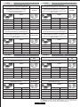
Foyers
TABLES DE CUISSON
4 gaz
QC / R / SR / A
4 gaz
UR / R / SR / A
5 gaz
QC / 2R / SR / A
4 gaz
QC / R / SR / A
S67 / HBGPX
1
1
2
3
S67 / HBGPX S67 / HBGPX S67 / HBGPX
YES YES YES YES
1
111
1
1
11
1111
11
2
1
9.25 kW 8.75
kW 11.75 kW 9.25 kW
673 L/h 636 L/h 854 L/h 673 L/h
3333
220-240 V / 50-60 Hz 220-240 V / 50-60 Hz 220-240 V / 50-60 Hz 220-240 V / 50-60 Hz
15 W15 W15 W15 W
YES
595 x 510
YES
595 x 510
YES
745 x 510
YES
745 x 510
Table 1
881 L/h
833 L/h
1119 L/h 881 L/h
Modèle
Sécurité gaz par thermocouple
Brûleur auxiliaire(AØ 50 mm)
Brûleur quadruple couronne (QC Ø 135 mm)
Brûleur ultra rapide (UR Ø 110 mm)
Brûleur semi-rapide(SR Ø 75 mm)
Brûleur rapide(R Ø 100 mm)
Type de gaz installé / Puissance :
Puissance totale
G 20/20 mbar (Gaz de naturel : Méthane)
G 30/28-30 mbar (Butane/Propane)
Classe d'installation
Voltage
/ Frequency V / Hz
Puissance électrique
Allumage électronique intégré
Dimensions appareil (LxP) mm
Cet appareil a été dessiné pour un usage non professionnel, usage domestique uniquement

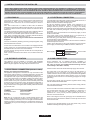
1. INSTRUCTIONS FOR THE INSTALLER
The hob may be installed in any worktop which is heat resistant to a
temperature of 100°C, and has a thickness of 25-45 mm. The
dimensions of the insert to be cut out of the worktop are in shown in
Figure 2.
If the Hob is fitted next to a cabinet
on either side, the distance
between the Hob and the cabinet must be at least 15 cm (see Figure
4); while the distance between the hob and the rear wall must be at
least 5,5 cm.
The distance between the hob and any other unit or appliance above it
(e.g. An
extractor hood) must be no less than 70 cm (Figure 4).
When there is an accessible space between the built-in hob and the
cavity below, a dividing wall made of insulating material should be
inserted (wood or a similar material) (Figure 3).
Important - The diagram in figure 1 shows how
the sealant should
be applied.
The Hob unit is fitted by attaching the Fixing Clamps supplied, using
the holes at the base of the unit.
If a hob of 60 cm is fitted above an oven which is not equipped with fan
cooling system it is recommended that openings are created
within
the built in furniture to ensure correct air circulation.
The size of these openings must be at least 300 cm2 and placed as
shown in Figure 5.
When a 75 cm hob is fitted over a built in oven, the latter must be fan
cooled.
2. ELECTRICAL CONNECTION (FOR U.K. ONLY)
Warning - this appliance must be earthed
This appliance is designed for domestic use only. Connection to the
main supply must be made by a competant electrician, ensuring that
all current regulations concerning such installations are observed.
The appliance must only be connected to a suitably rated spur point, a
3 pin
13 amp plug/socket is not suitable. A double pole switch must be
provided and the circuit must have appropriate fuse protection.
Further details of the power requirement of the individual product will
be found in the users’ instruction and on the appliance rating plate. In
the case of built-in product
you are advised, should you wish to use a
longer cable than the one supplied, that a suitably rated heat resistant
type must be used.
The wiring must be connected to the mains supply as follows:
CONNECT TO SPUR TERMINAL
Green & Yellow Wire Earth Connection
Blue Wire Neutral Connection
Brown Wire Live
Connection
Note: We do not advocate the use of earth leakage devices with
electric cooking appliances installed to spur points because of the
«nuisance tripping» which may occur. You are again reminded that the
appliance must be correctly earthed, the manufacturer declines any
responsibility for any event occurring as a result
of incorrect electrical
installation.
07 GB - IE
INSTALLING A DOMESTIC APPLIANCE CAN BE A COMPLICATED OPERATION WHICH IF NOT CARRIED OUT CORRECTLY, CAN SERIOUSLY
AFFECT CONSUMER SAFETY. IT IS FOR THIS REASON THAT THE TASK SHOULD BE UNDERTAKEN BY A PROFESSIONALLY QUALIFIED
PERSON WHO WILL CARRY IT OUT IN ACCORDANCE WITH THE TECHNICAL REGULATIONS IN FORCE. IN THE
EVENT THAT THIS ADVICE IS
IGNORED AND THE INSTALLATION IS CARRIED OUT BY AN UNQUALIFIED PERSON, THE MANUFACTURER DECLINES ALL RESPONSIBILITY
FOR ANY TECHNICAL FAILURE OF THE PRODUCT WHETHER OR NOT IT RESULTS IN DAMAGE TO GOODS OR INJURY TO INDIVIDUALS.
1.1 BUILDING IN
1.2. SUITABLE LOCATION
This appliance must be installed in accordance with applicable
regulations and should only be used in well-ventilated locations.
Before using this appliance carefully study the instruction book.
2.1. ELECTRICAL CONNECTION
Check the data on the rating plate, located on the outside of the unit, to
ensure that the supply and input voltage are suitable.
Before connection, check the earthing system.
By Law, this appliance must be earthed. If this regulation is not
complied with, the Manufacturer will not be responsible for any
damage caused to persons or property. If a plug is not already
attached, fit a plug appropriate to the load indicated on the rating plate.
The earth wire is coloured yellow/green. The plug should always be
accessible.
Where the Hob is connected direct to the electricity supply, a circuit
breaker must
be fitted.
If the power supply cord is damaged this is to be replaced by a
qualified engineer so as to prevent any potential risk.
The earth wire ( green and yellow coloured ) must be at least 10 mm
longer than the live and neutral wires.
The section of the cable
used must be of the correct size in relation to
the absorbed power of the hob.
Please check rating plate for the power details and ensure that the
power supply cord is of the type H05RR-F, H05VV-F, H05V2V2-F.
LIVE
EARTH
NEUTRAL
L
N
Power Cable
Brown Wire
Green/Yellow Wire
Blue Wire
Mains Supply
2.2. GAS CONNECTION
These instructions are for qualified personnel, installation of
equipment must be in line with the relevant national standard. (For
U.K. only: by law the gas installation\commissioning must be
carried out by a "Gas Safe" installer)
All work must be carried out with the electricity supply disconnected.
The rating plate on the
hob shows the type of gas with which it is
designed to be used. Connection to the mains gas supply or gas
cylinder should be carried out after having checked that it is regulated
for the type of gas with which it will be supplied. If it is not correctly
regulated
see the instructions in the following paragraphs to change
gas setting
For liquid gas (cylinder gas) use pressure regulators which comply
with the relevant national standards.
Use only pipes,washers and sealing washers which comply with the
relevant national standards.
To prevent any potential damage to the hob please carry out the
installation
following this sequence (picture 6):
For some models a conic link is furnished to outfit for the installation in
the countries where this type of link is obligatory; in picture 8 it is
pointed out how to recognize the different types of links (CY =
cylindrical, CO = conic). In every
case the cylindrical part of the link
has to be connected to the hob.
When connecting the hob to the gas supply via use offlexible hoses
please ensure that the maximum distance covered by the hose does
not exceed 2 metres.

2.3. ADAPTING THE HOB TO DIFFERENT
TYPES OF GAS
To adapt the Hob for use with different types of gas, carry out the
following instructions:
•remove the grids and burners
•insert on hexagonal spanner (7 mm) into the burner support (Figure
7)
•Unscrew the injector and replace it with one suitable for the gas to be
used (see gas type table)
1)As illustrated, assemble parts in sequence:
A: 1/2 Male Adaptor Cylindirical
B: 1/2 Seal
C: 1/2 Female Gas Adaptor Conical-Cylindirical or
Cylindirical-Cylindirical
2)Tighten the joints with the spanner, remembering to twist the
pipes into position.
3)Attach fitting C to mains gas supply using rigid copper pipe or
flexible steel pipe.
IMPORTANT: carry out a final check for leaks on the pipe
connections using a soapy solution. NEVER USE A FLAME. Also,
make sure that the flexible pipe cannot come into contact with a
moving part of the cabinet (eg.adrawer) and that it is not situated
where it could be damaged.
Warning:
If gas can be smelt in the vicinity of this appliance turn off the gas
supply to the appliance and call the engineer directly. Do not search for a
leak with a naked flame.
2.4. REGULATING THE MINIMUM FLAME
After lighting the burners, turn the control knob to the minimum setting
and then remove the knob (this can easily be removed by applying
gentle pressure).
Using a small «Terminal» type screwdriver the regulating screw can
be adjusted as in Figure 9. Turning the screw clockwise reduces the
gas flow, whilst
turning it anticlockwise increases the flow – Use this
adjustment to obtain a flame of approximately 3 to 4 mm in length and
then replace the control knob.
When the gas supply available is LPG - the screw to set the idle flame
must be turned (clockwise) to the end stop.
When
you have carried out the new gas regulation, replace the old gas
rating plate on your appliance with one (supplied with hob) suitable for
the type of gas for which it has been regulated.
3. USE OF HOB - USER INSTRUCTIONS
This appliance must only be used for the purpose for which it is
intended, domestic cooking, and any other use will be considered
improper and could therefore be dangerous. The Manufacturer will
not be responsible for any damage or loss resulting from improper
use.
This appliance is not intended for use
by persons (including children)
with reduced physical, sensory or mental capabilities, or lack of
experience and knowledge, unless they have been given supervision
or instruction concerning use of the appliance by a person responsible
for their safety.
Children should be supervised to ensure that they do not play with the
appliance.
3.1. USING THE GAS BURNER
To ignite the burners, place a lighted taper close to the burner, press in
and turn the control knob anti-clockwise.
If the burners have not been used for a couple of days, wait for a few
seconds before lighting the burner, this will allow any air present in the
pipes to
escape.
For appliances fitted with electronic ignition carry out the following:
• push in and turn the knob anticlockwise to the ignition symbol.
• ignite the burner by pressing the sparker button.
For hobs fitted with automatic ignition simply push in and turn the knob
to the ignition symbol.
The ignition system will
continue to generate sparks as long as the
control knob is being pressed.
If the burner has not ignited within 5 seconds, turn the knob to the 0
position and repeat the operation.
For models fitted with a safety tap (which cuts-off the flow of gas if the
flame is accidentally extinguished)
the burners are ignited and
described above, but care must be taken.
Prior to switching on the gas hob ensure that the burners and burner
caps are correctly placed within their position.
GENERAL ADVISE
For best results, use cooking vessels with a flat surface. The size of
the surface should match
the gas burner side as follows. Table A.
08 GB - IE
For smaller containers the gas burner should be regulated so that the
flame does not overlap the base of the pan. Vessels with a concave or
convex base should not be used.
WARNING: If a flame is accidentally extinguished, turn the knob
to the off position and do not attempt to
re-ignite if for at least 1
minute.
If over the years the gas taps become stiff to turn it is necessary to
lubricate them.
Such operation must be carried out only by qualified Service
Engineers.
Burner Type
Ø pan / pot (cm)
AUX
SR
R
UR
QC
12 - 18
18 - 24
24 - 26
24 - 28
24 - 28
Auxiliary Burner
Semi Rapid Burner
Rapid Burner
Ultra Rapid Burner
Double Ring Burner
Table A

4. MAINTENANCE AND CLEANING
Before cleaning the hob, ensure the appliance has cooled down.
Remove the plug from the socket or (if connected directly) switch off
the electricity supply.
Never use abrasives, corrosive detergents, bleaching agents or
acids. Avoid any acid or alkaline substances (lemon, juice, vinegar
etc.) on the enamelled, varnished or stainless steel
sections.
When cleaning the enamelled, varnished or chrome sections, use
warm soapy water or a non caustic detergent. For stainless steel use
an appropriate cleaning solution.
The burners can be cleaned with soapy water. To restore their original
shine, use a household stainless steel cleaner. After cleaning, dry the
burners and
replace.
It is important the Burners are replaced correctly.
Chromed grids and burners
"WARNING” - Do not use a steam cleaner to clean the hob.
Chromed grids and burners have a tendency to discolour with use.
This does not jeopardize the functionality of the hob.
Our After Sales Service Centre can provide
spare parts if required.
5. AFTERCARE
Before calling out a Service Engineer please check the following:
• that the plug is correctly inserted and fused;
• that the gas supply is not faulty.
If the fault cannot be detected:
Switch off the appliance and call the After Service Centre. DO NOT
TAMPER WITH THE APPLIANCE.
This appliance is marked according to the European
directive 2002/96/EC on Waste Electrical and
Electronic Equipment (WEEE).
By ensuring this product is disposed of correctly, you
will help prevent potential negative consequences for
the environment and human health, which could
otherwise be caused by inappropriate waste handling
of this product.
The symbol
on the product indicates that this product may not be
treated as household waste. Instead it shall be handed over to the
applicable collection point for the recycling of electrical and electronic
equipment.
Disposal must be carried out in accordance with local environmental
regulations for waste disposal.
For more detailed information
about treatment, recovery and recycling
of this product, please contact your local city office, your household
waste disposal service or the shop where you purchased the product.
6. PROTECTION OF THE ENVIRONMENT
09 GB - IE
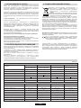
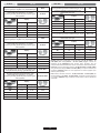
This appliance has been designed for non-professional, i.e. domestic, use.
Burner
BUILT IN HOBS
Type / reference
Flame failure device
Auxiliary burner ( AUX Ø 50 mm)
Double ring burner ( QC Ø 135 mm)
Ultra rapid burner ( UR Ø 110 mm)
Semirapid burner ( SR Ø 75 mm)
Rapid burner ( R
Ø 100 mm)
Installed Gas Type / Power:
G 20/20 mbar (methane)
G 30/28-30 mbar (LPG)
Installation Class
Voltage / Frequency V / Hz
Electrical input power
Electric ignition
Product dimension
4 gas
QC / R / SR / AUX
4 gas
UR / R / SR / AUX
5 gas
QC / 2R / SR / AUX
4 gas
QC / R / SR / AUX
S67 / HBGPX
1
1
2
3
S67 / HBGPX S67 / HBGPX S67 / HBGPX
YES YES YES YES
1
111
1
1
11
1111
11
2
1
9.25 kW 8.75
kW 11.75 kW 9.25 kW
673 L/h 636 L/h 854 L/h 673 L/h
3333
220-240 V / 50-60 Hz 220-240 V / 50-60 Hz 220-240 V / 50-60 Hz 220-240 V / 50-60 Hz
15 W15 W15 W15 W
YES
595 x 510
YES
595 x 510
YES
745 x 510
YES
745 x 510
Table 1
Power
881 L/h
833 L/h
1119 L/h 881 L/h
The Manufacturer will not be responsible for any inaccuracy resulting from
printing or transcript errors contained in this brochure. We reserve the right
to carry out modifications to products as required, including the interests of
consumption, without prejiudice to the characteristics relating to safety or
function.
Declaration of compliance: This equipment, in the parts intended to
come into contact with food, complies with the regulations laid down in
EEC directives 89/109.
Appliance complies with European Directives 73/23/EEC
and 89/336/EEC, replaced by 2006/95/EC and
2004/108/EC, and subsequent amendments.

1. ИНСТРУКЦИИ ПО ВЫПОЛНЕНИЮ УСТАНОВКИ
Варочная поверхность может устанавливаться на любой рабочей
поверхности кухонного стола, которая выдерживает нагрев до
температуры 100 °С, и имеет толщину от 25 до 40 мм. Размеры
отверстия, которое должно быть вырезано в рабочей поверхности
кухонного стола, показаны на рис. 2.
Если варочная поверхность устанавливается так, что по обе ее стороны
располагаются
шкафы, то расстояние между варочной поверхностью и
шкафом должно быть не меньше 15 см (см. рис. 4), а расстояние между
варочной поверхностью и расположенной сзади стеной должно быть не
меньше 5,5 см.
Расстояние между варочной поверхностью и другим электроприбором
(например, вытяжной колпак) должно быть не меньше 70 см (см. рис. 4).
Если
под варочной поверхностью имеется свободное пространство, то
под варочной поверхностью нужно установить разделительную панель,
изготовленную из теплоизоляционного материала (например, из дерева)
(см. рис. 3).
Важная информация На рис. 1 показано, как наносится герметик
Варочная поверхность крепится с помощью фиксирующих зажимов,
которые вставляются в отверстия, расположенные на основании
варочной поверхности.
Если варочная
поверхность 60 см устанавливается над духовкой, в
которой нет системы охлаждения с вентилятором, то во встраиваемой
мебели рекомендуется сделать отверстия для обеспечения нормальной
циркуляции воздуха.
Площадь этих отверстий должна быть не меньше 300 см2 и эти
отверстия должны располагаться так, как показано на рис. 5.
Если варочная поверхность 75 см крепится
над духовкой, то в духовке
должна быть система охлаждения с вентилятором.
Внимание данный электроприбор должен быть заземлен
Данный электроприбор предназначен только для бытовых
применений. Подключение к электросети должно выполняться только
опытным электриком с соблюдением всех действующих привил и норм
электробезопасности.
Данный электроприбор должен подключаться к ответвлению
электросети с достаточной нагрузочной способностью. 3-штырьковая
вилка/розетка на 13 А не подходит для данного подключения. В
линии
электропитания должен быть установлен двухполюсный выключатель,
и цепь должна быть защищена с помощью плавкого предохранителя
соответствующего номинала. Более подробная информация
относительно требований, предъявляемых к электропитанию для
конкретного изделия, представлена в инструкции по эксплуатации и в
паспортной табличке, закрепленной на изделии. Если длина кабеля
питания, поставляемого в комплекте с варочной
поверхностью,
является недостаточной, то следует использовать более длинный
тепл остойк ий кабель питания с дос таточ ной нагрузочной
способностью. Подключение к электросети должно быть выполнено
следующим образом:
ПОДСОЕДИНИТЕ К КЛЕММЕ ОТВОДА ЭЛЕКТРОСЕТИ
Зелено-желтый провод Земля
Синий провод Нейтраль
Коричневый провод Фаза
Примечание: Не подключайте варочную поверхность через
устройство обнаружения утечки тока на землю, так как это может
привести к "ложным отключениям".
Еще раз напоминаем, что
электроприбор должен быть правильно заземлен, и что производитель
не принимает никаких претензий в случае повреждений и несчастных
случаев, возникших в результате неправильного подключения
электроприбора к электросети.
10 RU
УСТАНОВКА БЫТОВОЙ ТЕХНИКИ ЯВЛЯЕТСЯ СЛОЖНОЙ РАБОТОЙ, НЕПРАВИЛЬНОЕ ВЫПОЛНЕНИЕ КОТОРОЙ МОЖЕТ ОТРИЦАТЕЛЬНО
СКАЗАТЬСЯ НА БЕЗОПАСНОСТИ ПОЛЬЗОВАТЕЛЯ. ПО ЭТОЙ ПРИЧИНЕ УСТАНОВКА БЫТОВОЙ ТЕХНИКИ ДОЛЖНА ВЫПОЛНЯТЬСЯ
ВЫСОКОКВАЛИФИЦИРОВАННЫМИ СПЕЦИАЛИСТАМИ, КОТОРЫЕ ВЫПОЛНЯТ УСТАНОВКУ С СОБЛЮДЕНИЕМ ВСЕХ ДЕЙСТВУЮЩИХ ПРАВИЛ
И НОРМ. В ТОМ СЛУЧАЕ, ЕСЛИ ЭТО ПРЕДОСТЕРЕЖЕНИЕ БУДЕТ ПРОИГНОРИРОВАНО, И УСТАНОВКА БУДЕТ ВЫПОЛНЕНА ЛИЦОМ, НЕ
ИМЕЮЩИМ ДОСТАТОЧНОЙ
КВАЛИФИКАЦИИ, ПРОИЗВОДИТЕЛЬ НЕ БУДЕТ ПРИНИМАТЬ НИКАКИХ ПРЕТЕНЗИЙ ОТНОСИТЕЛЬНО ВЫХОДА
ОБОРУДОВАНИЯ ИЗ СТРОЯ И НАНЕСЕННОГО ПРИ ЭТОМ УЩЕРБА ИМУЩЕСТВУ ИЛИ ЗДОРОВЬЮ ЛЮДЕЙ.
1.1. ВСТРАИВАЕМЫЕ ВАРОЧНЫЕ ПОВЕРХНОСТИ
1.2. ВЫБОР МЕСТА ДЛЯ УСТАНОВКИ
ВАРОЧНОЙ ПОВЕРХНОСТИ
Данный бытовой электроприбор дол жен устанавливаться в
соответствии с действующими правилами и нормами для бытовых
приборов и должен эксплуатироваться только в хорошо
вент или руемы х помещениях. Перед тем как приступить к
эксплуатации данной варочной поверхности внимательно прочтите
инструкцию по эксплуатации.
2.1. ПОДКЛЮЧЕНИЕ К ЭЛЕКТРОСЕТИ
Проверьте данные, приведенные в паспортной табличке,
закрепленной снаружи на варочной поверхности, для того, чтобы
убедиться в том, что входное напряжение варочной поверхности
соответствует напряжению электросети.
Перед подключением варочной поверхности к электросети проверьте
систему заземления.
Данный электроприбор обязательно должен быть заземлен. В
случае несоблюдения этого требования производитель снимает с
себя ответственность за нанесение
вреда здоровью людей и
повреждение имущества. Если к кабелю питания не подсоединена
вилка, подсоедините к кабелю питания вилк у, нагрузочная
способность которой соответствует ук азанной в паспортной
табличке. Провод заземления имеет желто-зеленый цвет. К
электрической розетке должен всегда обеспечиваться свободный
доступ.
Если варочная поверхность подключается к электросети напрямую,
то должен быть установлен
автоматический выключатель.
Для предотвращения опасностей замена поврежденного кабеля
питания должна выполняться тольк о квалифицированным
специалистом.
Провод заземления (желто-зеленый) должен быть приблизительно
на 10 мм длиннее проводов фазы и нейтрали.
Сечение проводников кабеля питания должно соответствует
мощности, потребляемой варочной поверхностью.
Проверьте значение мощности, потребляемой электроприбором,
указанное в паспортной табл ич ке, а такж е проверьте, что
используется кабель
питания типа HO5RR-F, H05VV-F или HO5V2V-F.
ФАЗА
ЗЕМЛЯ
НЕЙТРАЛЬ
L
N
Кабель
питания
Коричневый провод
Желто-зеленый провод
Синий провод
Линия
электропитания
2.2. ПОДКЛЮЧЕНИЕ К ЛИНИИ ГАЗОСНАБЖЕНИЯ
Данные инструкции предназначены для специалистов, имеющих
достаточную квалификацию для выполнения установки оборудования
в соответствии с требованиями национальных правил и норм. Только
для Великобритании. Согласно закон у, установка/ввод в
эксплуатацию должны выполняться только сотрудником службы
"Gas Safe".
Все работы должны выполняться с отсоединенным электропитанием.
В закрепленной на варочной поверхности паспортной табличке указан
тип газа,
на котором должна работать варочная поверхность. Перед
подключением варочной поверхности к линии газоснабжения или к
газовому баллону необходимо проверить, что варочная поверхность
отрегулирована на тот тип газа, который будет в нее подаваться. Если
варочная поверхность не отрегулирована на нужный тип газа,
обратитесь к инструкциям, приведенным в последующих параграфах,
где описано,
как изменить регулировки.
При работе на сжиженном газе (газ в баллоне) следует пользоваться
регулятором давления, отвечающего требованиям национальных
стандартов.
Трубы, шайбы и уплотнительные прокладки должны соответствовать
требованиям национальных стандартов.
Некоторые модели поставляются с коленом (переходником), имеющим
коническую резьбу. В некоторых странах использование таких
переходников является обязательным. На рис. 8 показано, как
отличить
переходник с цилиндрической резьбой от переходника с
конической резьбой (CY = цилиндрическая, СО = коническая). В любом
случае цилиндрическая резьба должна быть
В любом случае, конец переходника с цилиндрической резьбой должен
подсоединяться к варочной поверхности.
Если подключение варочной поверхности к линии газоснабжения
осуществляется с помощью гибкого шланга, проверьте, что длина
гибкого
шланга не превышает 2 м.
Чтобы не повредить варочную поверхность, выполните ее установку,
как описано (см. рис. 6).
2. ПОДКЛЮЧЕНИЕ К ЭЛЕКТРОСЕТИ
(ТОЛЬКО ДЛЯ ВЕЛИКОБРИТАНИИ)

2.3. АДАПТАЦИЯ ВАРОЧНОЙ ПОВЕРХНОСТИ
НА ДРУГИЕ ТИПЫ ГАЗА
Для адаптации варочной поверхности для работы с другими газами
выполните описанные ниже инструкции:
•снимите решетки и конфорки
•вставьте шестигранный ключ (7 мм) в основание конфорки (рис. 7)
•Выверните форсунку и замените ее форсункой, соответствующей
тому типу газа, который будет использоваться (см. таблицу типов
газа).
1) Подсоедините детали, как показано на рисунке:
А) Переходник с наружной цилиндрической резьбой 1/2 дюйма
В) Прокладка 1/2 дюйма
С) Газовый переходник с внутренней резьбой 1/2 дюйма,
коническая цилиндрическая, или цилиндрическая
цилиндрическая.
2) Затяните соединение с помощью гаечных ключей. Перед тем
как затянуть соединение установите трубы в ну жное
положение.
3) Подсоедините колено
С к линии подачи газа с помощью
жесткой медной трубы или гибкой стальной трубы.
ВАЖНОЕ ЗАМЕЧАНИЕ: После подсоединения варочной
поверхности к линии газоснабжения проверьте на отсутствие
утечек газа все трубные соединения с помощью мыльного
раствора. НИКОГДА НЕ ИСПОЛЬЗУЙТЕ ДЛЯ ПРОВЕРКИ
УТЕЧЕК ГАЗА ПЛАМЯ. Проверьте также, что гибкий шланг не
соприкасается с
движущимися частями кухонной мебели
(например, выдвижной ящик) и не проходит в таком месте, где
он может быть поврежден.
Предупреждение: Если вблизи ва р очн ой поверхности вы
почувствуете запах газа, перекройте подачу газа на варочную
поверхность и вызовите специалиста. Не ищите место утечки газа с
помощью открытого пламени.
2.4. РЕГУЛИРОВКА МИНИМАЛЬНОГО ПЛАМЕНИ
После зажигания конфорки установите ручку регулятора высоты
пламени в положение, соответствующее минимальному пламени, а
затем снимите ручку регулятора, приложив небольшое усилие.
Регулировка минимального пламени выполняется с помощью винта и
маленькой отвертки, как показано на рис. 9. Поворот винта по
часовой стрелке уменьшает поток газа, а поворот винта против
часовой стрелки увеличивает
поток газа. С помощью этой
регулировки получите пламя высотой 3-4 мм, а затем установите на
место ручку регулятора.
Если используется сжиженный нефтяной газ (СНГ), поверните винт
до упора по часовой стрелке.
После выполнения регулировок для адаптации варочной
поверхности на другой тип газа замените старую табличку,
закрепленную на варочной поверхности, в которой
указан тип газа, на
новую (поставляется в комплекте с варочной поверхностью), в
которой указан тип газа, на который переведена варочная
поверхность.
3. ИНСТРУКЦИИ ПО ЭКСПЛУАТАЦИИ
ВАРОЧНОЙ ПОВЕРХНОСТИ
Данный электроприбор предназначен только для использования по
его прямому назначению, то есть, для приготовления пищи в
домашних услов иях . Любое другое применение варочной
поверхности считается неправильным, и поэтому может быть
опасным. Производитель не несет ответственности за повреждения и
потери, являющиеся следствием неправильного использования
варочной поверхности.
Данный электроприбор не предназначен для использования людьми
с ограниченными физическими или умственными способностями,
людьми, не обладающими достаточным опытом и знаниями, а также
для использования детьми, если они не находятся под наблюдением
лица, отвечающего за их безопасность, или не получили от него
соответствующих инструкций.
Не разрешайте детям играть с электроприбором.
3.1 ИСПОЛЬЗОВАНИЕ ГАЗОВОЙ КОНФОРКИ
Чтобы зажечь конфорку, поднесите к ней зажженную спичку,
нажмите на ручку регулировки высоты пламени, и поверните ее
против часовой стрелки.
Если конфорки не использовались в течение двух или более
дней, то прежде чем зажечь конфорку подождите несколько
секунд для того, чтобы из трубок вышел воздух.
Чтобы зажечь конфорку варочной поверхности, снабженную
устройством
электроподжига, выполните следующие операции:
• нажмите на ручку регулировки высоты пламени и поверните ее
против часовой стрелки в положение, обозначенное поджига.
• зажгите конфорку с помощью нажатия кнопки электроподжига.
Если варочная поверхность снабжена автоматическим
электроподжигом, просто нажмите на ручку регулировки высоты
пламени и установите ее в положение, обозначенное значком
поджига. Система
электроподжига будет постоянно
генерировать искры, до тех пор, пока ручка регулировки пламени
будет находиться в нажатом положении.
Если конфорка не загорается в течение 5 секунд, установите
ручку регулировки в положение 0, и повторите описанную выше
операцию.
В моделях, снабженных защитным клапаном, который
автоматически перекрывает подачу газа в случае внезапного
погасания пламени, конфорки
зажигаются, как описано выше, но
при этом после зажигания конфорки необходимо соблюдать
осторожность.
Перед включением газовой варочной поверхности проверьте, что
конфорки и крышки конфорок правильно установлены на
варочную поверхность.
ПОЛЕЗНЫЕ СОВЕТЫ
Для получения наилучших результатов пользуйтесь
сковородами и кастрюлями с плоским дном, размеры которых
соответствуют размерам газовых конфорок (см. Табл. А).
11 RU
При использовании сковороды или кастрюли меньшего размера
пламя должно быть отрегулировано таким образом, чтобы оно не
выходило за пределы дна сковороды или кастрюли. Не следует
пользоваться посудой с выпуклым или вогнутым дном.
ПРЕДУПРЕЖДЕНИЕ: Если горелка случайно погаснет,
установите ручку регулировки в положение ВЫКЛ., и не
пытайтесь зажечь пламя в течение, по
крайней мере, одной
минуты.
Если через несколько лет работы варочной поверхности газовые
краны будут туго поворачиваться, то их необходимо смазать.
Эта работа должна выполняться только
квалифицированным специалистом по обслуживанию.
Тип конфорки
Ø сковороды/кастрюли (cm)
AUX
SR
R
UR
QC
12 - 18
18 - 24
24 - 26
24 - 28
24 - 28
Маленькая конфорка
Полубыстрая конфорка
Быстрая конфорка
Сверхбыстрая конфорка
Конфорка с двумя венцами
Таблица A

4. ОБСЛУЖИВАНИЕ И ЧИСТКА
Перед тем как приступить к выполнению чистки варочной
поверхности, проверьте, что она остыла. Выньте вилку из розетки,
или (если варочная поверхность подсоединена к электросети
напрямую), выключите питающее напряжение.
Запрещается использовать абразивные и коррозирующие чистящие
средства, отбеливающие вещества, или кислоты. Не пользуйтесь
для чистки эмалированных и лакированных деталей, а также деталей
из
нержавеющей стали кислотами и щелочами (лимонный сок, уксус
и т. п.)
ПРЕДУПРЕЖДЕНИЕ Не пользуйтесь для чистки варочной
поверхности пароочистителями.
Очистка эмалированных, лакированных и хромированных
поверхностей должна выполняться с помощью мыльной воды или
нейтрального моющего средства. Для очистки поверхностей из
нержавеющей стали необходимо пол ьзоваться подходящим
чистящим раствором.
Конфорки мож но очищать с помощью
мыльной воды. Для
восстановления их первоначального блеска используйте бытовое
чистящее средство для нержавеющей стали. После чистки горелок
высушите их и установите на место.
Проследите за тем, чтобы конфорки были собраны правильно.
Хромированные решетки и конфорки
Хромированные решетки и конфорки со временем темнеют.
Это нормальное и неизбежное явление, которое не оказывает
негативного влияния на
работу варочной поверхности.
Вы можете приобрести запасные части в отделе послепродажного
обслуживания нашей компании.
5. ПОСЛЕПРОДАЖНОЕ ОБСЛУЖИВАНИЕ
Перед тем как вызвать специалиста по техническому обслуживанию
для выполнения ремонта варочной поверхности, выполните
следующие проверки:
• Проверьте, что вилка кабеля питания правильно вставлена в
электрическую розетку, и что не перегорел плавкий предохранитель.
• Проверьте, что газ подается.
Если вы не можете самостоятельно определить причину
неисправности:
Выключите варочную поверхность и обратитесь в
цент р
послепродажного обслуживания. НЕ ПЫТАЙТЕСЬ
ОТРЕМОНТИРОВАТЬ ЭЛЕКТРОПРИБОР САМОСТОЯТЕЛЬНО.
Данный электроприбор промаркирован в
соответствии с требованиями, изложенными в
директиве 2002/96/ЕС относительно утилизации
электрического и электронного оборудования
(WEEE).
Правильно выполняя утилизацию данного изделия,
вы поможете предотвратить загрязнение окружающей
среды и нанесение вреда здоровью людей.
Этот символ указывает на то, что данное изделие не должно
выбрасываться, как обычный бытовой мусор. Вместо этого
оно
должно быть отправлено на пункт сбора отслужившего свой срок
электрического и электронного оборудования для выполнения его
последующей утилизации и повторного использования материалов.
Утилизация данного изделия должна выполняться в соответствии с
местными законами по охране окружающей среды.
Для получения более подробной информации относительно
обработки, восстановления и повторного использования материалов
данного изделия, свяжитесь
с органами местной власти, службой
вывоза бытовых отходов, или торговой организацией, в которой вы
приобрели данное изделие.
6. ЗАЩИТА ОКРУЖАЮЩЕЙ СРЕДЫ
12 RU
Данное изделие предназначено только для бытовых применений.
Конфорки
ВСТРАИВАЕМЫЕ ВАРОЧНЫЕ ПОВЕРХНОСТИ
Тип / обозначение
Устройство защиты от погасания пламени
Маленькая конфорка ( AUX Ø 50 mm)
Конфорка с двумя венцами ( QC Ø 135 mm)
Сверхбыстрая конфорка ( UR Ø 110 mm)
Полубыстрая конфорка ( SR Ø 75 mm)
Быстрая конфорка ( R Ø 100 mm)
Используемый газ / мощность:
G20/20 мбар (метан)
G30/28-30 мбар (СНГ)
Класс установки
Напряжение/Частота В/Гц
Входная электрическая мощность
Электроподжиг
Размеры варочной поверхности
4 газовые
QC / R / SR / AUX
4
UR / R / SR / AUX
газовые 5
QC / 2R / SR / AUX
газовые 4
QC / R / SR / AUX
газовые
S67 / HBGPX
1
1
2
3
S67 / HBGPX S67 / HBGPX S67 / HBGPX
ДА ДА
ДА ДА
1
111
1
1
11
1111
11
2
1
9.25 кВт 8.75 кВт 11.75
кВт 9.25 кВт
673 л/час 636 л/час
854 л/час
673 л/час
3333
220-240 / 50-60 220-240 / 50-60 220-240 / 50-60 220-240 / 50-60
15 Вт 15 Вт 15 Вт 15 Вт
ДА
595 x 510
ДА
595 x 510
ДА
745 x 510
ДА
745 x 510
Таблица 1
Мощность
881 л/час
833 л/час
1119 л/час 881 л/час
Производитель не несет ответственности за опечатки и
неточности, которые могут встретиться в данной инструкции.
Мы оставляем за собой право вносить изменения в конструкцию
выпускаемых нами изделий с целью улучшения качества
выпускаемой продукции. При этом основные функции изделия и его
безопасность будут оставаться неизменными.
Декларация соответствия: Данное оборудование, детали которого
вступают в контакт с пищей, отвечает требованиям Европейской
директивы 89/109/ЕЕС.
Этот электроприбор соответствует требованиям
Европейских директив 73/23/EEC и 89/336/EEC, которые
были заменены директивами 2006/95/ЕС и 2004/108/ЕС, и
последующих поправок к ним.
* Установка производителя
IE категория II2H3 +GB категория II2H3 +

Ø mm Ø mm
Ø mm Ø mm
Ø mm Ø mm
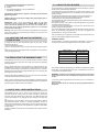
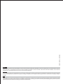
GAS TYPEPHOENIX
UWAGA! PL G2.350 - 13 mbar (Ls ) Jeśli G2.350 - 13 mbar (Ls ) jest używany
można wykorzystac dysze o kodzie 35000239, Bardzo prosimy o zaopatrywanie
autoryzowanym serwisie.
II2ELs3B/P
Rodzaj gazu/Type de gaz/Gassoort/Gasart
G20
Cisnienie gazu/Pression gaz/Gasdruck
20 mbar
Max (kW) Min (kW)
AUX
SR
R
UR
QC
1.00
1.75
2.50
3.50
4.00
0.23
0.36
0.53
1.20
1.75
0.76
1.01
1.18
1.44
1.45
PL
P (Kw)
Rodzaj gazu/Type de gaz/Gassoort/Gasart
G30
Cisnienie gazu/Pression gaz/Gasdruck
37 mbar
Max (kW) Min (kW)
AUX
SR
R
UR
QC
1.20
2.00
2.80
3.80
4.00
0.26
0.41
0.62
1.20
1.90
P (Kw)
0.50
0.66
0.80
0.94
0.96
Rodzaj gazu/Type de gaz/Gassoort/Gasart
G2.350
Cisnienie gazu/Pression gaz/Gasdruck
13 mbar
Max (kW) Min (kW)
AUX
SR
R
UR
QC
1.00
1.75
2.50
3.50
3.50
0.23
0.36
0.53
1.20
1.75
P (Kw)
1.04
1.32
1.60
1.90
1.90
II2HS3B/P
Gaz tipusa
G20
Gaz nyomasa
25 mbar
Max (kW) Min (kW)
AUX
SR
R
UR
QC
1.20
2.00
2.80
3.80
4.00
0.26
0.41
0.62
1.20
1.90
0.76
1.01
1.18
1.44
1.41
HU
P (Kw)
Gaz tipusa
G25.1
Gaz nyomasa
25 mbar
Max (kW) Min (kW)
AUX
SR
R
UR
QC
0.90
1.60
2.25
3.80
3.50
0.23
0.36
0.53
1.20
1.75
P (Kw)
0.76
1.01
1.18
1.60
1.45
Gaz tipusa
G30 / G31
Gaz nyomasa
30 / 30 mbar
Max (kW) Min (kW)
AUX
SR
R
UR
QC
1.00
1.75
2.50
3.50
4.00
0.23
0.36
0.53
1.20
1.75
P (Kw)
0.50
0.66
0.80
0.94
0.99
QC/UR
AUX
SR
R
QC
AUX
SR
R
QC / UR
AUX
SR
RR
12 3
13

II 2L 3B/P
Tipo di gas/Gas type/Gassoort/Gasart/Type de gaz
G25
Pressione gas/Gas pressure/Pression gaz/
Gasdruck/Presion gas
25 mbar
Max (kW)
Min (kW)
AUX
SR
R
UR
QC
0.90
1.60
2.25
3.40
3.70
0.23
0.36
0.53
1.20
1.75
0.76
1.01
1.18
1.44
1.45
NL
P (Kw)
Tipo di gas/Gas type/Gassoort/Gasart/Type de gaz
G30 / G31
Pressione gas/Gas pressure/Pression gaz/
Gasdruck/Presion gas
30/30 mbar
Max (kW)
Min (kW)
AUX
SR
R
UR
QC
1.00
1.75
2.50
3.50
4.00
0.23
0.36
0.53
1.20
1.75
P (Kw)
0.50
0.66
0.80
0.94
0.99
Wichtig:Österreich, Deutschland und der Schweiz-AT, DE, CH G30/31-50 mbar
(3B/P) Beim Gastyp G30/31-50 mbar (3B/P) dagegen müssen die Gasdüsen Art.-
Nr. 35000238 benutzt werden. Bitte bestellen Sie die entsprechenden
Gasdüsensätze bei unserem autorisierten Werkskundendienst.
Max (kW)
Min (kW)
AUX
SR
R
UR
QC
1.00
1.75
2.50
3.50
4.00
0.23
0.36
0.53
1.20
1.75
0.76
1.01
1.18
1.44
1.45
P (Kw)
Tipo di gas/Gas type/Gassoort/Gasart/Type de gaz
G30 / G31
Pressione gas/Gas pressure/Pression gaz/
Gasdruck/Presion gas
50/50 mbar
Max (kW)
Min (kW)
AUX
SR
R
UR
QC
1.00
1.75
3.00
3.50
4.00
0.30
0.45
0.70
1.20
2.20
P (Kw)
0.46
0.58
0.79
0.94
0.89
II 2E 3B/P
Tipo di gas/Gas type/Gassoort/Gasart/Type de gaz
G20
Pressione gas/Gas pressure/Pression gaz/
Gasdruck/Presion gas
20 mbar
DE
II 2H3+
Tipo di gas/Gas type/Gassoort/Gasart/Type de gaz
Tipo de gás/Tύттоς αερіоυ/Gaz type/Gaz Tipi
G20
Pressione gas/Gas pressure/Pression gaz/
Gasdruck/Presion gas/Πίεση του αερίου/
Pressão gás/Tlak plina/Ciśnienie gazu/
Gáz nyomása/Gaz Basıncı
20 mbar
Max (kW) Min (kW)
AUX
SR
R
UR
QC
1.00
1.75
2.50
3.50
4.00
0.23
0.36
0.53
1.20
1.75
0.76
1.01
1.18
1.44
1.45
CY, CZ, GB, GR, IE, IT, PT, SI, ES, CH, TR
P (Kw)
Tipo di gas/Gas type/Gassoort/Gasart/Type de gaz/
Tipo de gás/Tύттоς αερіоυ/Tipo de gás/Gaz type/
Vrsta plina/Pritisk plina/Typ gazu/Rodzaj gazu
G30 / G31
Pressione gas/Gas pressure/Pression gaz/
Gasdruck/Presion gas/Πίεση του αερίου/
Pressão gás/Tlak gasa/Tlak plina/Ciśnienie gazu/
Gáz nyomása
28-30/37 mbar
Max (kW) Min (kW)
AUX
SR
R
UR
QC
1.00
1.75
2.50
3.50
4.00
0.23
0.36
0.53
1.20
1.75
P (Kw)
0.50
0.66
0.80
0.94
0.99
II 2H3B/P
Tipo di gas/Gas type/Gassoort/Gasart/
Type de gaz/Tipo de gás/Tύттоς αερіоυ/Gaz type
G20
Pressione gas/Gas pressure/Pression gaz/
Gasdruck/Presion gas/Πίεση του αερίου/
Pressão gás/Tlak gasa/Tlak plina/Ciśnienie gazu/
Gáz nyomása
20 mbar
Max (kW) Min (kW)
AUX
SR
R
UR
QC
1.00
1.75
2.50
3.50
4.00
0.23
0.36
0.53
1.20
1.75
0.76
1.01
1.18
1.44
1.45
BG, HR, DK, EE, FI, LV, LT, NO, RO, SK, SE
P (Kw)
Tipo di gas/Gas type/Gassoort/Gasart/Type de gaz/
Tipo de gás/Tύттоς αερіоυ/Tipo de gás/Gaz type/
Vrsta plina/Pritisk plina/Typ gazu/Rodzaj gazu
G30 / G31
Pressione gas/Gas pressure/Pression gaz/
Gasdruck/Presion gas/Πίεση του αερίου/
Pressão gás/Tlak gasa/Tlak plina/Ciśnienie gazu/
Gáz nyomása
30/30 mbar
Max (kW) Min (kW)
AUX
SR
R
UR
QC
1.00
1.75
2.50
3.50
4.00
0.23
0.36
0.53
1.20
1.75
P (Kw)
0.50
0.66
0.80
0.94
0.99
Ø mm
Ø mmØ mm
Ø mm
Ø mm Ø mm
Ø mmØ mm
14

II 2E+3+
Tipo di gas/Gas type/Gassoort/Gasart/
Type de gaz/Tipo de gás/Tύттоς αερіоυ/Gaz type
G20
Pressione gas/Gas pressure/Pression gaz/
Gasdruck/Presion gas/Πίεση του αερίου/
Pressão gás/Tlak gasa/Tlak plina/Ciśnienie gazu/
Gáz nyomása
20 mbar
Max (kW)
Min (kW)
AUX
SR
R
UR
QC
1.00
1.75
2.50
3.50
4.00
0.23
0.36
0.53
1.20
1.75
0.76
1.01
1.18
1.44
1.45
FR, BE
P (Kw)
Tipo di gas/Gas type/Gassoort/Gasart/
Type de gaz/Tipo de gás/Tύттоς αερіоυ/Gaz type
G25
Pressione gas/Gas pressure/Pression gaz/
Gasdruck/Presion gas/Πίεση του αερίου/
Pressão gás/Tlak gasa/Tlak plina/Ciśnienie gazu/
Gáz nyomása
25 mbar
Max (kW) Min (kW)
AUX
SR
R
UR
QC
0.90
1.60
2.25
3.40
3.70
0.23
0.36
0.53
1.20
1.75
P (Kw)
0.76
1.01
1.18
1.44
1.45
Tipo di gas/Gas type/Gassoort/Gasart/Type de gaz/
Tipo de gás/Tύттоς αερіоυ/Tipo de gás/Gaz type/
Vrsta plina/Pritisk plina/Typ gazu/Rodzaj gazu
G30 / G31
Pressione gas/Gas pressure/Pression gaz/
Gasdruck/Presion gas/Πίεση του αερίου/
Pressão gás/Tlak gasa/Tlak plina/Ciśnienie gazu/
Gáz nyomása
28-30/37 mbar
Max (kW) Min (kW)
AUX
SR
R
UR
QC
0.23
0.36
0.53
1.20
1.75
P (Kw)
1.00
1.75
2.50
3.50
4.00
0.50
0.66
0.80
0.94
0.99
0.46
0.58
0.79
0.94
0.89
Wichtig: Österreich, Deutschland und der Schweiz - AT, DE, CH G30/31 - 50
mbar (3B/P) Beim Gastyp G30/31 - 50 mbar (3B/P) dagegen müssen die
Gasdüsen Art.-Nr.35000238 benutzt werden. Bitte bestellen Sie die
entsprechenden Gasdüsensätze bei unserem autorisierten Werkskundendienst
Remarque : Autriche, Allemagne et Suisse - AT , DE, CH G30/31 -
50 mbar (3B/P)
Si le gaz utilisé est de type G30/31 - 50 mbar (3B/P), vous pouvez utiliser le jeu
d’injecteurs 35000238. Merci de vous rapprocher du service approprié pour
obtenir le jeu d’injecteurs.
Nota: Austria, Germania, Svizzera - AT, DE, CH G30/31 - 50 mbar (3B/P) Se
dovete installare
il gas G30/31 - 50 mbar (3B/P), va utilizzato il il set di iniettori di
cui al codice 35000238. Prego richiedere il set di iniettori al servizio assistenza
autorizzato
II2H 3B/P
Tipo di gas/Gas type/Gassoort/Gasart/Type de gaz
G20
Pressione gas/Gas pressure/Pression gaz/
Gasdruck/Presion gas
20 mbar
Max (kW) Min (kW)
AUX
SR
R
UR
QC
1.00
1.75
2.50
3.50
4.00
0.23
0.36
0.53
1.20
1.75
0.76
1.01
1.18
1.44
1.45
AT, CH
P (Kw)
Tipo di gas/Gas type/Gassoort/Gasart/Type de gaz
G30 / G31
Pressione gas/Gas pressure/Pression gaz/
Gasdruck/Presion gas
50/50 mbar
Max (kW) Min (kW)
AUX
SR
R
UR
QC
1.00
1.75
3.00
3.50
4.00
0.30
0.45
0.70
1.20
2.20
P (Kw)
Ø mm
Ø mm
Ø mm
Ø mm
Ø mm
15

GB - IE
The manufacturer will not be responsible for any inaccuracy resulting from printing or transcript errors contained in this brochure. We reserve the right
to carry out modifications to products as required, including the interests of con sumption, without prejudice to the characteri stics relating to safety or
function.
06.2010 • REV:A • 42803496
FR
Le constructeur décline toute responsabilité concernant d'éventuelles inexacitudes imputables à des erreurs d'impression ou de transcription contenue
dans cette notice. Le constructeur se réserve le droit de modifier les produits en cas de nécessité, même dans l'intérêt de l'utilisation, sans causer de
préjudices aux caractéristiques de fonctionnement de sécurité des appareils.
RU
Производитель не несет ответственности за опечатки и неточности, которые могут встретиться в данной инструкции. Мы оставляем за собой
право вносить изменения в конструкцию выпускаемых нами изделий с целью улучшения качества выпускаемой продукции. При этом основные
функции изделия и его безопасность будут оставаться неизменными.
-
 1
1
-
 2
2
-
 3
3
-
 4
4
-
 5
5
-
 6
6
-
 7
7
-
 8
8
-
 9
9
-
 10
10
-
 11
11
-
 12
12
-
 13
13
-
 14
14
-
 15
15
-
 16
16


ROSIERES RTG 64 Le manuel du propriétaire
- Taper
- Le manuel du propriétaire
dans d''autres langues
- English: ROSIERES RTG 64 Owner's manual
- русский: ROSIERES RTG 64 Инструкция по применению
Documents connexes
Autres documents
-
Zerowatt ZHW6LCX Manuel utilisateur
-
Candy CHW6LWW Manuel utilisateur
-
-
-
Hoover 33801235 Manuel utilisateur
-
Hoover HGV75SXV B Manuel utilisateur
-
-
-
-