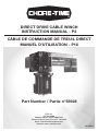
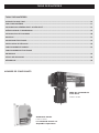
Chore-Time MF2498A Direct Drive Cable Winch Mode d'emploi
- Taper
- Mode d'emploi

DIRECT DRIVE CABLE WINCH
INSTRUCTION MANUAL - P2
CÂBLE DE COMMANDE DE TREUIL DIRECT
MANUEL D’UTILISATION - P16
Part Number / Partie n°56928
CTB, Inc.
PO Box 2000
Milford, Indiana 46542-2000 USA
Phone (574) 658-4101 Fax (877) 730-8825
Email: [email protected]
Internet: www.choretime.com
MF2498A

2
CHORE-TIME WARRANTY
LIMITED WARRANTY
CTB, Inc. (“Chore-Time”) warrants the new CHORE-TIME Direct Drive Winch to be free from defects in material or
workmanship under normal usage and conditions, for One (1) year from the date of installation by the original purchaser
(“Warranty”). Chore-Time provides for an extension of the aforementioned Warranty period (“Extended Warranty Period”)
with respect to certain Product parts. If such a defect is determined by Chore-Time to exist within the applicable period,
Chore-Time will, at its option, (a) repair the Product or Component Part free of charge, F.O.B. the factory of manufacture or
(b) replace the Product or Component Part free of charge, F.O.B. the factory of manufacture. This Warranty is not
transferable, and applies only to the original purchaser of the Product.
CONDITIONS AND LIMITATIONS
THIS WARRANTY CONSTITUTES CHORE-TIME’S ENTIRE AND SOLE WARRANTY AND CHORE-TIME EXPRESSLY
DISCLAIMS ANY AND ALL OTHER WARRANTIES, INCLUDING, BUT NOT LIMITED TO, EXPRESS AND IMPLIED
WARRANTIES, INCLUDING, WITHOUT LIMITATION, WARRANTIES AS TO MERCHANTABILITY OR FITNESS FOR
PARTICULAR PURPOSES.
CHORE-TIME shall not be liable for any direct, indirect, incidental, consequential or special damages which any purchaser
may suffer or claim to suffer as a result of any defect in the Product. Consequential or Special Damages as used herein
include, but are not limited to, lost or damaged products or goods, costs of transportation, lost sales, lost orders, lost
income, increased overhead, labor and incidental costs, and operational inefficiencies. Some jurisdictions prohibit limitations
on implied warranties and/or the exclusion or limitation of such damages, so these limitations and exclusions may not apply
to you. This warranty gives the original purchaser specific legal rights. You may also have other rights based upon your
specific jurisdiction.
Compliance with federal, state and local rules which apply to the location, installation and use of the Product are the
responsibility of the original purchaser, and CHORE-TIME shall not be liable for any damages which may result from non-
compliance with such rules.
• The following circumstances shall render this Warranty void:
• Modifications made to the Product not specifically delineated in the Product manual.
• Product not installed and/or operated in accordance with the instructions published by the CHORE-TIME.
• All components of the Product are not original equipment supplied by CHORE-TIME.
• Product was not purchased from and/or installed by a CHORE-TIME authorized distributor or certified
representative.
• Product experienced malfunction or failure resulting from misuse, abuse, mismanagement, negligence, alteration,
accident, or lack of proper maintenance, or from lightning strikes, electrical power surges or interruption of electricity.
• Product experienced corrosion, material deterioration and/or equipment malfunction caused by or consistent with the
application of chemicals, minerals, sediments or other foreign elements.
• Product was used for any purpose other than for the care of poultry and livestock.
The Warranty and Extended Warranty may only be modified in writing by an officer of CHORE-TIME. CHORE-TIME shall
have no obligation or responsibility for any representations or warranties made by or on behalf of any distributor, dealer,
agent or certified representative.
Effective: April 2014

3
TABLE OF CONTENTS
CONTENTS
CHORE-TIME WARRANTY ............................................................................................................................................2
TABLE OF CONTENTS .................................................................................................................................................... 3
SAFETY AND GENERAL INFORMATION .......................................................................................................................4
SPECIFICATIONS AND DIMENSIONS ............................................................................................................................ 5
INTRODUCTION AND PLANNING ..................................................................................................................................6
MOUNTING ......................................................................................................................................................................7
ELECTRICAL CONNECTION ......................................................................................................................................... 10
SETUP AND ADJUSTMENT ..........................................................................................................................................12
MANUAL OPERATION ..................................................................................................................................................13
ELECTRICAL OPERATION ............................................................................................................................................ 13
MAINTENANCE ............................................................................................................................................................14
SERVICE PARTS ...........................................................................................................................................................15
TROUBLESHOOTING ....................................................................................................................................................15
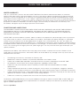
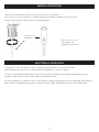
PART NUMBERS
Direct Drive Winch
Part No. 56928
Wall Control
Part No. 56930
Wall control is available
separately

4
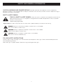
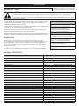
Signal words are used in conjunction with the safety–alert symbol to identify the severity of the warning.
DANGER indicates an imminently hazardous situation which, if not avoided,
WILL result in death or serious injury.
WARNING indicates a potentially hazardous situation which, if not avoided,
COULD result in death or serious injury.
CAUTION indicates a hazardous situation which, if not avoided,
MAY result in minor or moderate injury.
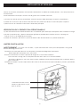
SAFETY AND GENERAL INFORMATION
CAUTION, WARNING AND DANGER DECALS have been placed on the equipment to warn of potentially
dangerous situations. Care should be taken to keep this information intact and easy to read at all times. Replace missing or
damaged safety decals immediately.
SAFETY–ALERT SYMBOL
FOLLOW SAFETY INSTRUCTIONS
Carefully read all safety messages in this manual and on your equipment safety signs. Follow recommended precautions
and safe operating practices.
Keep safety signs in good condition. Replace missing or damaged safety signs.
THIS IS A SAFETY–ALERT SYMBOL. When you see this symbol on your equipment, be alert to the
potential for personal injury. This equipment is designed to be installed and operated as safely as possible...
however, hazards do exist.
Understanding Signal Words

5
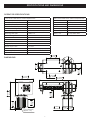
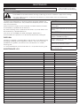
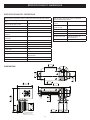
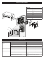
SPECIFICATIONS AND DIMENSIONS
OPERATOR SPECIFICATIONS
DIMENSIONS
Direct Drive Cable Winch General Specification
Lift Capacity Max. (lbs) 2,205
Lift Speed (ft/min) 7.5
Drum Torque (ft-lbs) 240
Drum Diameter (inch) 2.56
Maximum Lift Height (ft) 12.8
Suitable Rope Size 3/16” 7 x 19 (6mm max)
Mounting Bolt Spec 4 XM12 HT
Drum Bearing 207-SB20
Limits 2 X NC MICRO SWITCH
IP Code IP55
Manual Operation Use 13mm Socket
Weight (lbs) 100
Approx Cycle Time 3.42 mins
Suitable Controller 56930 Wall Control (sep. avail.)
Operating Temperature 10°C - 40°C / 50°F - 104°F
Application Indoor use only
Direct Drive Cable Winch Electrical Specification
Motor Power 1.5Hp, 1.1kW
Full Load Current 7.1 Amp
Voltage 230V
Phase 1 (2 x Hot Wire)
Frequency 60Hz
Capacitor (Uf) Run-35 / Start 200
Motor Fuse 12 Amp Slow Blow
6.890in
175mm
23.750in
603mm
2.618in
66.5mm
3.543in
90mm
8.346in
212mm
5.906in
150mm
4 -
0.551in
14mm
5.906in
150mm
0.512in
13mm
18.465in
469mm
11.535in
293mm
13 mm Hex(A/F)
[Approx: 1/2"]

6
INTRODUCTION AND PLANNING
INTRODUCTION
Congratulations on your purchase of the Chore-Time Feeder Cable Winch. This winch stands alone in the market as the
fastest and most robust winch of its kind. The installation of a Chore-Time Feeder Cable Winch ensures extreme longevity
and trouble free operation.
PLANNING
The Direct Drive Cable Winch is designed to be installed inside livestock buildings to lift feeder and drinker lines (and other
similar systems) between the ground level and ceiling space.
The Direct Drive Cable Winch features a single phase motor coupled to a drive system comprising two cam activated limit
switches to allow stopping at the fully lowered and raised positions.
Suitable controls will be required to switch the motor direction and accept the limits switch inputs.
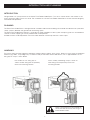
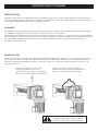
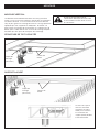
HANDLING
Ensure you wear personal protection equipment (proper clothing, gloves, dust masks). Never use your hands at dangerous
locations (eg cables, sharp edges etc). In order to safely lift the Direct Drive Cable Winch, use an approved M12 or 1/2"
lifting eye or strap as shown below:
Use an M12 or 1/2" lifting eye as
shown to allow lifting into the proximity
of the final mounting location
Use a suitably rated lifting strap as shown to
allow lifting into the proximity of the final
mounting location
When using the lifting strap method, be
aware that the winch may not hang in a
balanced orientation.

7
MOUNTING
An electrician must disconnect electric
power to the winch and control before
removing or opening covers.
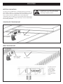
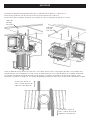
VERTICAL MOUNTING
The Direct Drive Cable Winch is designed to be mounted to a
concealed or web truss structure in livestock buildings. The roof
truss structure must be engineered to ensure mounting of the
winch and the relevant applied loads will be adequately
supported. Refer to page 5 for mounting bolt hole spacing and
size for fabrication of a suitable mounting structure. Refer below
for mounting examples.
CONCEALED TRUSS MOUNT
WEB TRUSS MOUNT
Mounting plate
(not supplied)
Truss braces
Truss braces
Ensure the winch
is mounted so
that the cable
passes through
the web truss
openings during
travel
Mounting plate
(not supplied)

8
MOUNTING
An electrician must disconnect electric
power to the winch and control before
removing or opening covers.
HORIZONTAL MOUNTING
The Direct Drive Cable Winch is designed to be mounted to a
concealed or web truss structure in livestock buildings. The roof
truss structure must be engineered to ensure mounting of the
winch and the relevant applied loads will be adequately
supported. Refer to page 5 for mounting bolt hole spacing and
size for fabrication of a suitable mounting structure. Refer below
for mounting examples.
CONCEALED TRUSS MOUNT - HORIZONTAL
WEB TRUSS MOUNT - HORIZONTAL
Truss braces
Truss braces
Ensure the winch
is mounted so
that the cable
passes through
the web truss
openings during
travel
Mounting plate
(not supplied)
Mounting plate
(not supplied)

9
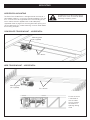
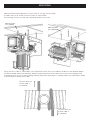
MOUNTING
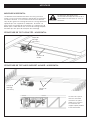
Mount the Direct Drive Cable Winch using 4 x M12 or 1/2"High Tensile (Grade
8.8) bolts and nuts to secure the winch in place as shown below.
Ensure spring washers are used and a tightening torque of 29-33 ft/lb.
Set up the winch cable as shown below. You should have at least one turn of cable on the drum in each direction before
the load is applied. Clamp the cable firmly beneath the bolt head and washer. Note: The manual crank coupling can be
used during set up to assist cable wrapping and other adjustment (refer page 13). Guiding pulleys may need to be installed
to ensure correct tracking of the cable.
Ensure at least 10ft
of clear cable in
this direction
Ensure at least 10ft
of clear cable in
this direction
Mounting plate
(not supplied)
Mounting plate
(not supplied)

10
ELECTRICAL CONNECTION
THE DIRECT DRIVE CABLE WINCH MUST:
• BE CONNECTED IN ACCORDANCE WITH THE WIRING RULES OF THE COUNTRY IN
WHICH IT IS INSTALLED
• NOT HAVE ENCLOSURES LEFT OPEN FOR EXTENDED PERIODS (EXCESS DUST WILL
VOID WARRANTY)
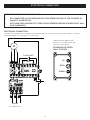
ELECTRICAL CONNECTION
The Direct Drive Cable Winch is designed to be operated with the Chore-Time reversing starter controls. The internal
connection diagram for single phase is shown below:
L2L1
L2
F
L1
R
E
MAINS
UP LIMIT
DOWN LIMIT
E
M
230V SUPPLY IN
Operation of the above control
panels is via a simple two position
control as shown below.
REVERSING STARTER
WALL CONTROL
STOP
UP
DOWN

11
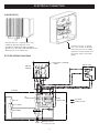
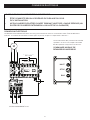
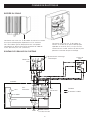
ELECTRICAL CONNECTION
CABLE ENTRY
SYSTEM WIRING DIAGRAM
Connect with min. 18 gauge wire using
conduit or gland to meet min IP55.
Suitable UL listed Liquid Tight Cordgrips
(glands) must be used; cable diameter 0.260”
(Minimum) to 0.545” (Maximum).
Connect with min. 18 gauge
wire using conduit or gland to
meet minimum IP55 (If rubber
grommet is fitted, remove and
discard to allow use of cable
gland).
Sw
GREY
BLUE
RED
L2
F
EARTH
R
L1
Rw
Cr
Cs
RED
BLUE
WHITE
RECS-220P
L2
L1 L2
F
L1
NC- E-STOP
NO- UP
NO-DOWN
Winch Limits
WINCH
MOTOR
R
DOWN
CONTACTOR
Pre-wired
Installer to wire
UP
CONTACTOR
E
Electronic Centrifugal
Switch
Controller
SPLIT PHASE
MAINS SUPPLY
LI-115V, L2-115V
NC
NC

12
With primary connection of the winch complete in accordance with relevant control box, it is time to test the operation.
Carefully follow the next steps to ensure safe setup:
1) Ensure the winch is properly secured and the lift cables clamped accordingly.
2) Check and make sure both limit cams are positioned away from their relevant micro switches.
3) Secure all covers, and supply mains power.
CHECKING OPERATIONAL DIRECTION
4) Operate the winch momentarily in one direction to check that the UP switch will lift the load.
5) If incorrect, isolate mains power and proceed as follows: (ref page 10)
- Swap F and R on the single phase model
6) Secure covers, supply power to the system, and check for correct operational direction.
SETTING LIMITS
WARNING: Limits are sensitive; a small cam movement may correspond to a large amount winch travel.
- Position one cam to depress a switch (the other should be well clear of the switch)
- Note the switch that you have activated
- Supply power and activate in up direction momentarily
- If the winch lifts up then the limit switch noted above is the lower limit
- If the winch doesn't move it is the upper limit (momentarily activate in the close direction to confirm this)
- Proceed to adjust each friction held cam and operate the winch to achieve the required set positions.
SETUP AND ADJUSTMENT
Friction held limit cams.
Use a small flat blade
screwdriver to adjust

13
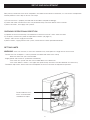
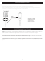
MANUAL OPERATION
13mm or 1/2 In
Hex Socket
NOTE: 13mm or 1/2 In
Hex Socket is not
supplied with the winch
Isolate mains power before using the manual crank feature as shown below.
Use a 13mm (1/2 in) hex socket with a suitable drive bit (not included) to operate the winch manually.
Rotation of the socket will operate the winch in either direction.
In operation the winch will require the user to hold the controlling switch to raise or lower the load.
During operation the cable must lay neatly into the tracking grooves as shown on page 9.
The winch should operate quietly with only the hum of the motor, and perhaps some pulley noise depending on the
condition and/or lubrication of the various pulleys connected to the load.
If the winch produces any abnormal noises such as grinding, rattling or squeaking, cease use immediately and isolate the
power. Refer to Troubleshooting on page 14, and/or contact a suitably qualified technician to inspect and/or repair.
ELECTRICAL OPERATION

14
MAINTENANCE
DANGER!
Power MUST be turned off before servicing or adjusting the winch. Isolate the supply when cleaning!
Any works requiring access to electrical connections or junction boxes must be carried out by
a qualified electrician!
WINCH MODEL
The Direct Drive Cable Winch is built for extreme service life and does not
need any internal maintenance. Only trained and competent persons should
carry out maintenance.
Certain mechanical aspects of the installation should be routinely checked
and rectified by a qualified fitter or electrician.
Any works requiring access to electrical connections or junction boxes must
be carried out by a qualified electrician.
If the winch has exceeded the stated working life, replacement is
recommended. All inspections must be monthly beyond the working life.
DISPOSAL
If disposal is required, it should be done using the most up-to-date recycling
technology according to local regulations and laws. Drain oil via the plug
provided on the gearbox, and contain it for safe disposal at a suitable
recycling yard.
It is recommended that the winch be taken to a scrap metal recycling yard.
MAINTENANCE LOG
MONTHLY
Inspect for signs of wear or damage to
lifting cables
Check proper operation of the winch (lift/
lower)
QUARTERLY
Check tightness of fixing bolts and
tighten if needed (ref page 7)
Check mounting structure, including
welds / fasteners etc
Check for any abnormal noises
Brush down and wipe over the winch
with a damp cloth
MONTHLY DATE CHECKED / COMPLETE (SIGN)
Inspect for signs of wear or damage to lifting cables
Check proper operation of the winch (lift/lower)
MONTHLY DATE CHECKED / COMPLETE (SIGN)
Inspect for signs of wear or damage to lifting cables
Check proper operation of the winch (lift/lower)
MONTHLY DATE CHECKED / COMPLETE (SIGN)
Inspect for signs of wear or damage to lifting cables
Check proper operation of the winch (lift/lower)
QUARTERLY DATE CHECKED / COMPLETE (SIGN)
Check tightness of fixing bolts and tighten if needed (ref pg 7)
Check mounting structure, including welds / fasteners etc
Check for any abnormal noises
Brush down and wipe over the winch with a damp cloth
MONTHLY DATE CHECKED / COMPLETE (SIGN)
Inspect for signs of wear or damage to lifting cables
Check proper operation of the winch (lift/lower)
MONTHLY DATE CHECKED / COMPLETE (SIGN)
Inspect for signs of wear or damage to lifting cables
Check proper operation of the winch (lift/lower)
MONTHLY DATE CHECKED / COMPLETE (SIGN)
Inspect for signs of wear or damage to lifting cables
Check proper operation of the winch (lift/lower)
QUARTERLY DATE CHECKED / COMPLETE (SIGN)
Check tightness of fixing bolts and tighten if needed (ref pg 7)
Check mounting structure, including welds / fasteners etc
Check for any abnormal noises
Brush down and wipe over the winch with a damp cloth
(Copy multiples of this blank
form for future record keeping)

15
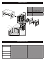
SERVICE PARTS
Part Number Description
56949 Limit switch box cover
56950 Limit switch box base
56951 Limit switch assembly
56932 Motor 230V 60Hz Single Phase
56952 Motor terminal box complete
56954 Motor Run Capacitor
56955 Motor Start Capacitor
56931 Winch gearbox assembly
56932
56931
56952
56955
56954
56950
56951
56949
Problem Possible Cause Action
Winch does not raise or lower No power Restore power supply
Both limit cams activated Check / adjust limit switches
Excess load - thermal overload tripped Reduce load, reset / adjust overload in control
Excess use - motor overheated Allow to cool
Electrical fault Check all electrical connections
Winch does not raise Upper limit activated Check / adjust limit switch
Electrical fault Check all electrical connections
Winch does not lower Lower limit activated Check / adjust limit switch
Electrical fault Check all electrical connections
Winch makes noise Cable misalignment Check/adjust cable alignment as it lays on to the drum
Motor to gearbox coupling loose Remove winch and return to Chore-Time for inspection
Internal gearbox noise Remove winch and return to Chore-Time for inspection
TROUBLESHOOTING

16
GARANTIE CHORE-TIME
LIMITE DE GARANTIE
CTB, Inc. («Chore-Time») garantit que le nouveau câble de commande de treuil direct CHORE-TIME est libre de tout
défaut dans ses matériaux ou sa fabrication dans le cadre d’une utilisation et de conditions normales, pendant un (1) an à
partir de la date d’installation par l’acheteur initial («Garantie»). Chore-Time fournit une extension de la sus-mentionnée
période de garantie («Extension de période de garantie») quant à certaines parties du produit. Si l’existence d’un défaut est
déterminée par Chore-Time au cours de la période applicable, Chore-Time devra, à sa discrétion, (a) réparer gratuitement la
pièce ou le produit, depuis ou par l’usine de fabrication ou (b) remplacer gratuitement la pièce ou le produit, depuis ou par
l’usine de fabrication. Cette garantie n’est pas transmissible et ne s’applique qu’à l’acheteur initial du produit.
CONDITIONS ET LIMITES
CETTE GARANTIE REPRÉSENTE LA SEULE ET TOTALE GARANTIE DE CHORE-TIME, ET CHORE-TIME DÉCLINE
EXPRESSÉMENT TOUTE AUTRE GARANTIE, COMPRENANT SANS S’Y LIMITER LES GARANTIES EXPRESSES ET
IMPLICITES, COMPRENANT SANS S’Y LIMITER LES GARANTIES QUANT À LA COMMERCIABILITÉ OU L’ADAPTATION À
UN USAGE PARTICULIER.
CHORE-TIME ne peut être tenu responsable pour tout dommage direct, indirect, fortuit, subséquent ou spécifique dont tout
acheteur pourrait subir ou déclarer subir suite à un défaut de production. Les dommages fortuits ou spéciaux cités dans la
présente comprennent sans s’y limiter la perte ou les dommages sur des produits ou biens, les coûts de transport, les
pertes de vente, la perte de commandes, la perte de revenus, des frais généraux plus élevés, des frais de travail ou fortuits
et inefficacités opérationnelles. Certaines juridictions interdisent les limites sur les garanties implicites et/ou l’exclusion ou
limite de tels dommages, dès lors ces limites et exclusions peuvent ne pas s’appliquer à vous. Cette garantie fournit à
l’acheteur initial des droits légaux spécifiques. Vous pouvez également disposer d’autres droits selon votre juridiction
spécifique.
Le respect des règles fédérales, nationales et locales qui s’appliquent à l’emplacement, l’installation et l’utilisation du produit
échoient à l’acheteur initial, et CHORE-TIME ne peut être tenu responsable de tout dommage qui résulterait d’un non-
respect de ces règles.
• Les circonstances suivantes doivent entraîner l’invalidité de cette Garantie:
• Modifications apportées au produit qui ne sont pas spécifiquement déterminées par le manuel du produit.
• Le produit n’est pas installé et/ou utilisé dans le respect des instructions publiées par CHORE-TIME.
• Tous les composants du produit ne sont pas l’équipement d’origine fourni par CHORE-TIME.
• Le produit n’a pas été acheté auprès de et/ou installé par un distributeur CHORE-TIME autorisé ou certifié
ou un représentant.
• Le produit connaît un dysfonctionnement ou une panne suite à une mauvaise utilisation, un usage forcé, une
mauvaise gestion, une négligence, une modification,
un accident, un manque d’entretien correct ou résultant d’un coup de foudre, une surcharge électrique ou une
coupure électrique.
• Le produit connaît une corrosion, une détérioration de matériel et/ou un mauvais fonctionnement de l’équipement dû
à ou suite à l’application de produits chimiques, minéraux, sédiments ou tout autre élément étranger.
• Le produit a été utilisé pour tout autre but que celui destiné au soin des volailles et bétail.
La Garante et extension de Garantie ne peuvent être modifiées que par écrit par un représentant de CHORE-TIME. CHORE-
TIME n’endosse aucune obligation ou responsabilité de toute représentation ou garantie incarnée par ou au nom de tout
distributeur, revendeur, agent ou représentant certifié.
Entrée en vigueur: Avril 2014

17
TABLE DES MATIÈRES
TABLE DES MATIÈRES
GARANTIE CHORE-TIME .............................................................................................................................................16
TABLE DES MATIÈRES .................................................................................................................................................17
INFORMATIONS GÉNÉRALES ET DE SÉCURITÉ ........................................................................................................ 18
SPÉCIFICATIONS ET DIMENSIONS .............................................................................................................................19
INTRODUCTION ET PLANNING ...................................................................................................................................20
MONTAGE ...................................................................................................................................................................... 21
CONNEXION ÉLECTRIQUE...........................................................................................................................................24
INSTALLATION ET RÉGLAGE .......................................................................................................................................26
FONCTIONNEMENT MANUEL ...................................................................................................................................... 27
FONCTIONNEMENT ÉLECTRIQUE
ENTRETIENT .................................................................................................................................................................28
PIÈCES DE RECHANGE ................................................................................................................................................ 29
DÉPANNAGE ..................................................................................................................................................................29
NOMBRE DE COMPOSANTS
Câble de commande de
treuil direct
Partie n°56928
Commande murale
Partie n°56930
La commande murale est
disponible séparément

18
Les mots de signalisation sont utilisés conjointement avec les symboles d’alerte de sécurité pour identifier la gravité de
l’avertissement.
DANGER indique une situation dangereuse immédiate qui, si elle n’est pas évitée, PROVOQUERA la mort ou
une blessure grave.
AVERTISSEMENT indique une situation potentiellement dangereuse qui, si elle n’est pas évitée, POURRAIT
provoquer la mort ou une blessure grave.
ATTENTION indique une situation dangereuse qui, si elle n’est pas évitée, POURRAIT provoquer une blessure
mineure ou moyenne.
INFORMATIONS GÉNÉRALES ET DE SÉCURITÉ
DES ÉTIQUETTES DE PRÉCAUTION, AVERTISSEMENT ET DANGER ont été placées sur l’équipement
afin de prévenir des potentielles situations dangereuses. Une attention particulière doit être protée afin de conserver ces
informations intactes et lisibles à tout moment. Remplacer toute étiquette de sécurité manquante ou endommagée
immédiatement.
SYMBOLES DE SÉCURITÉ - D’ALERTE
SUIVRE LES CONSIGNES DE SÉCURITÉ
Lire attentivement tous les messages de sécurité de ce manuel et sur les signaux de sécurité de votre équipement. Suivre
les précautions recommandées et les pratiques d’utilisation sécurisées.
Conserver les signaux de sécurité en bon état. Remplacer toute étiquette de sécurité manquante ou endommagée.
CECI EST UN SYMBOLE D’ALERTE DE SÉCURITÉ Lorsque vous voyez ce symbole sur votre
équipement, un risque de blessure personnelle est présent. Cet équipement est conçu pour être installé et
utilisé de manière aussi sécurisée que possible... toutefois, le risque est inhérent.
Comprendre les mots de signalisation

19
SPÉCIFICATIONS ET DIMENSIONS
SPÉCIFICATIONS DE L’OPÉRATEUR
DIMENSIONS
Spécifications générales pour le câble de commande de treuil direct
Capacité de levage maximum
(lbs)
2,205
Vitesse de levage (ft/min) 7,5
Couple de tambour (ft-lbs) 240
Diamètre du tambour (pouce) 2,56
Hauteur maximum de levée (ft) 12,8
Taille maximum de corde
adaptée
3/16” 7 x 19 (6mm max)
Spécificités de boulon de
montage
4 XM12 HT
Palier de tambour 207-SB20
Limites 2 X NC MICRO INTERRUPTEUR
Code IP IP55
Fonctionnement manuel Utiliser une prise de 13mm
Poids (lbs) 100
Temps de cycle approximatif 3,42 mins
Régulateur adapté Commande murale 56930 (vendue
séparément)
Température de fonctionnement 10°C - 40°C / 50°F - 104°F
Application Utilisation en intérieur uniquement
Spécifications électriques pour le câble de
commande de treuil direct
Puissance du
moteur
1,5Ch, 1.1kW
Courant nominal à
pleine charge
7,1 Amp
Voltage 230V
Phase 1 (2 x fil chaud)
Fréquence 60Hz
Condensateur (Uf) Fonctionnement-35 /
Démarrage 200
Fusible moteur 12 Amp fusion lente
6.890in
175mm
23.750in
603mm
2.618in
66.5mm
3.543in
90mm
8.346in
212mm
5.906in
150mm
4 -
0.551in
14mm
5.906in
150mm
0.512in
13mm
18.465in
469mm
11.535in
293mm
13 mm Hex(A/F)
[Approx: 1/2"]

20
INTRODUCTION ET PLANNING
INTRODUCTION
Félicitations pour votre achat du câble de treuil de mangeoire Chore-Time. Ce treuil se démarque sur le marché comme
étant le plus rapide et le plus robuste de sa catégorie. L’installation d’un câble de treuil de mangeoire Chore-Time garantit
une excellente longévité de fonctionnement en toute quiétude.
PLANNING
Le câble de commande de treuil direct est conçu pour être installé à l’intérieur des bâtiments abritant du détail afin de lever
les mangeoires et abreuvoirs (et autres systèmes similaires) entre le sol et le plafond.
Le câble de commande de treuil direct comprend un moteur monophasé couplé à un système de transmission comprenant
deux interrupteurs à came de fin de course qui permettent de stopper à la charge complète et à la position levée maximale.
Des commandes adaptées seront requises pour changer la direction du moteur et accepter les commandes des
interrupteurs de fin de course.
MANIPULATION
Assurez-vous de porter un équipements de protection individuelle (vêtements adaptés, gants, masque anti poussière). Ne
jamais placer vos mains dans des espacements dangereux (ex: câbles, bords tranchants, etc.). Afin de lever en toute
sécurité le câble de commande de treuil direct, utilisez une sangle ou un anneau de levage certifié M12 ou de 1/2" tel
qu’illustré ci-dessous:
Utilisez une sangle ou un anneau de
levage certifié M12 ou de 1/2" tel
qu’illustré ci-dessous pour vous permettre
de lever vers l’emplacement final de levage
Utilisez une sangle de levage certifiée tel
qu’illustré ci-dessous pour vous permettre de
lever vers l’emplacement final de levage
Lorsque vous utilisez la méthode de la
sangle de levage, faites attention à ce que le
treuil soit suspendu de manière équilibrée.
La page est en cours de chargement...
La page est en cours de chargement...
La page est en cours de chargement...
La page est en cours de chargement...
La page est en cours de chargement...
La page est en cours de chargement...
La page est en cours de chargement...
La page est en cours de chargement...
La page est en cours de chargement...
La page est en cours de chargement...
La page est en cours de chargement...
La page est en cours de chargement...
-
 1
1
-
 2
2
-
 3
3
-
 4
4
-
 5
5
-
 6
6
-
 7
7
-
 8
8
-
 9
9
-
 10
10
-
 11
11
-
 12
12
-
 13
13
-
 14
14
-
 15
15
-
 16
16
-
 17
17
-
 18
18
-
 19
19
-
 20
20
-
 21
21
-
 22
22
-
 23
23
-
 24
24
-
 25
25
-
 26
26
-
 27
27
-
 28
28
-
 29
29
-
 30
30
-
 31
31
-
 32
32


