Hitachi C 10FSHC Safety And Instruction Manual
- Catégorie
- Scies à onglet
- Taper
- Safety And Instruction Manual

DOUBLE INSULATION
DOUBLE ISOLATION
AISLAMIENTO DOBLE
Model
Modèle
Modelo
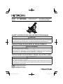
C 10FSHC
(Laser Marker Equipment)
(Outil avec marqueur à laser)
(Equipo marcador láser)
Slide Compound Miter Saw
Scie a coupe d’onglet radiale
Tronzadora radial abatible
SAFETY INSTRUCTIONS AND INSTRUCTION MANUAL
WARNING
IMPROPER OR UNSAFE use of this power tool can result in death or serious bodily injury!
This manual contains important information about product safety. Please read and understand
this manual before operating the power tool. Please keep this manual available for other users
and owners before they use the power tool. This manual should be stored in safe place.
INSTRUCTIONS DE SECURITE ET MODE D’EMPLOI
AVERTISSEMENT
Une utilisation INCORRECTE OU DANGEREUSE de cet outil motorisé peut entraîner la mort
ou de sérieuses blessures corporelles!
Ce mode d’emploi contient d’importantes informations à propos de la sécurité de ce produit.
Prière de lire et de comprendre ce mode d’emploi AVANT d’utiliser l’outil motorisé. Garder ce
mode d’emploi à la disponibilité des autres utilisateurs et propriétaires avant qu’ils utilisent
l’outil motorisé. Ce mode d’emploi doit être conservé dans un endroit sûr.
INSTRUCCIONES DE SEGURIDAD Y MANUAL DE INSTRUCCIONES
ADVERTENCIA
¡La utilización INAPROPIADA O PELIGROSA de esta herramienta eléctrica puede resultar
en lesiones de gravedad o la muerte!
Este manual contiene información importante sobre la seguridad del producto. Lea y
comprenda este manual ANTES de utilizar la herramienta eléctrica. Guarde este manual para
que puedan leerlo otras personas antes de utilizar la herramienta eléctrica. Este manual debe
ser guardado en un lugar seguro.

2
CONTENTS
TABLE DES MATIERES
ÍNDICE
English
Français
Español
Page
IMPORTANT SAFETY INFORMATION ...................3
MEANINGS OF SIGNAL WORDS ...........................3
SAFETY ......................................................................4
IMPORTANT SAFETY INSTRUCTIONS FOR
USING ALL POWER TOOLS ................................4
REPLACEMENT PARTS ..........................................8
USE PROPER EXTENSION CORD .........................8
DOUBLE INSULATION FOR SAFER OPERATION ....9
OPERATION AND MAINTENANCE ........................ 10
NAME OF PARTS...................................................10
SPECI FICATIO NS ..................................................12
ACCES S O RIES ...................................................... 13
APPLICATIONS ...................................................... 14
Page
INFORMATIONS IMPORTANTES DE
SÉCURITÉ ...........................................................42
SIGNIFICATION DES MOTS
D’AVERTISSEMENT ...........................................42
SECURITE ................................................................ 43
CONSIGNES DE SECURITE RELATIVES AUX
OUTILS ÉLECTRIQUES .....................................43
PIECES DE RECHANGE .......................................47
UTILISER LE CORDON DE RALLONGE
APPROPRIÉ ........................................................ 48
DOUBLE ISOLATION POUR UN
FONCTIONNEMENT PLUS SUR........................48
UTILISATION ET ENTRETIEN ................................50
NOM DES PIÈCES .................................................50
Página
INFORMACIÓN IMPORTANTE SOBRE
SEGURIDAD .......................................................84
SIGNIFICADO DE LAS PALABRAS DE
SEÑALIZACIÓN ..................................................84
SEGURIDAD .............................................................85
NORMAS DE SEGURIDAD PARA LAS
HERRAMIENTAS ELÉCTRICAS.........................85
PIEZAS DE REEMPLAZO......................................89
UTILICE EL CABLE PROLONGADOR
ADECUADO ........................................................90
AISLAMIENTO DOBLE PARA OFRECER UNA
OPERACIÓN MÁS SEGURA ..............................90
OPERACIÓN Y MANTENIMIENTO .........................9 2
NOMENCLATURA DE PARTES ............................92
ESPECIFICACIONES.............................................94
Page
PREPARATION BEFORE OPERATION ................14
BEFORE USING .................................................... 16
BEFORE CUTTING ................................................18
PRACTICAL APPLICATIONS ................................27
SAW BLADE MOUNTING AND DISMOUNTING ....37
MAINTENANCE AND INSPECTION .....................39
SERVICE AND REPAIRS ....................................... 41
PARTS LIST .......................................................... 126
Page
SPÉCI FICATIO NS .................................................. 52
ACCES S O I RES ......................................................5 3
APPLICATIONS ......................................................5 4
PRÉPARATION AVANT L’UTILISATION ................54
AVANT L’UTILISATION ..........................................56
AVANT LA COUPE .................................................58
APPLICATIONS PRATIQUES ................................68
INSTALLATION ET RETRAIT DE LA LAME ..........79
ENTRETIEN ET INSPECTION ...............................81
SERVICE APRÈS-VENTE ET RÉPARATIONS ......83
LISTE DES PIECES ..............................................126
Página
ACCESORIOS........................................................95
APLICACIONES .....................................................96
PREPARATIVOS PREVIOS A LA
OPERACIÓN ....................................................... 96
ANTES DE LA UTILIZACIÓN .................................98
ANTES DEL CORTE ............................................100
APLICACIONES PRÁCTICAS ............................. 110
MONTAJE Y DESMONTAJE DE LA
HOJA DE SIERRA .............................................120
MANTENIMIENTO E INSPECCIÓN .................... 123
SERVICIO Y REPARACIONES ............................125
LISTA DE PIEZAS .................................................126

3
English
IMPORTANT SAFETY INFORMATION
Read and understand all of the safety precautions, warnings and operating instructions in the
Instruction Manual before operating or maintaining this power tool.
Most accidents that result from power tool operation and maintenance are caused by the failure
to observe basic safety rules or precautions. An accident can often be avoided by recognizing a
potentially hazardous situation before it occurs, and by observing appropriate safety procedures.
Basic safety precautions are outlined in the “SAFETY” section of this Instruction Manual and in
the sections which contain the operation and maintenance instructions.
Hazards that must be avoided to prevent bodily injury or machine damage are identifi ed by
WARNINGS on the power tool and in this Instruction Manual.
NEVER use this power tool in a manner that has not been specifi cally recommended by
HITACHI.
MEANINGS OF SIGNAL WORDS
WARNING indicates a potentially hazardous situations which, if ignored, could result in death
or serious injury.
CAUTION indicates a potentially hazardous situations which, if not avoided, may result in
minor or moderate injury, or may cause machine damage.
NOTE emphasizes essential information.

4
English
SAFETY
IMPORTANT SAFETY INSTRUCTIONS
FOR USING ALL POWER TOOLS
READ ALL OF THE WARNINGS AND OPERATING INSTRUCTIONS IN THIS
MANUAL BEFORE OPERATING OR MAINTAINING THIS TOOL:
WARNING: When using this electric tool, take all necessary precautions to minimize
the risk of electric shock or other personal injury.
In particular, always comply with the following safety rules:
1. ALWAYS KEEP GUARDS IN PLACE and in working order.
2. ALWAYS REMOVE ADJUSTING KEYS AND WRENCHES BEFORE STARTING TOOL.
Always confi rm that all keys and adjusting wrenches have been removed from the tool
before it is turned on.
3. ALWAYS KEEP WORK AREA CLEAN. Avoid injuries by not cluttering the work areas and
work benches.
4. NEVER USE TOOL IN HAZARDOUS ENVIRONMENTS. Never use the power tool in damp
or wet places and never expose it to rain. Always keep the work area well lighted.
5. NEVER PERMIT CHILDREN OR OTHERS TO LOITER NEAR THE WORK AREA. Keep
all people (especially children) away from the work area. Always unplug unattended tools
and keep the work place tamper-proof by installing locks on the doors and on the master
switches. Always remove the lock- off button from the tool and store it in a secure place,
when the tool is not in use.
6. NEVER FORCE THE TOOL. It will do the job better and more safely if it is operated at the
rate for which it was designed.
7. ALWAYS USE THE RIGHT TOOLS. Never force a tool or an attachment to do a job for
which it was not designed.
8. ALWAYS WEAR PROPER APPAREL WHEN WORKING WITH THE TOOL. Never wear
loose clothing, gloves, neckties, rings, bracelets or other jewelry which may get caught in
the moving parts. Always wear non-slip footwear, preferably with steel toes. Wear protective
hair covering to contain long hair.
9. ALWAYS WEAR EYE PROTECTION WITH SIDE SHIELDS THAT MEETS THE
REQUIREMENTS OF ANSI STANDARD Z87.1 WHEN WORKING WITH THE TOOL TO
PREVENT EYE INJURY. Ordinary eyeglasses do not provide adequate protection because
they do not contain impact resistant safety glass. Also, use a face mask for additional safety
and wear a dust mask if the cutting operation produces dust.
10. ALWAYS SECURE THE WORKPIECE TO THE FENCE OR THE TABLE. Use clamps or a
vise to hold the workpiece in place. It is safer than using your hand and it frees both hands
to operate the tool.

5
English
11. NEVER OVERREACH. Always keep proper footing and balance when working with the
tool.
12. ALWAYS MAINTAIN TOOLS WITH CARE. Always keep tools sharp and clean for the best
and safest performance. Always follow instructions for lubricating the tool and for changing
accessories.
13. ALWAYS DISCONNECT THE TOOL before servicing and before changing blades or other
accessories.
14. NEVER RISK UNINTENTIONAL STARTING WHEN PLUGGING IN THE TOOL. Always
confi rm that the switch is in the OFF position before inserting the power plug into the
receptacle.
15. ALWAYS USE RECOMMENDED ACCESSORIES ONLY WHEN OPERATING THIS TOOL.
Consult this instruction manual for descriptions of recommended accessories. To avoid
personal injuries, use only recommended accessories in conjunction with this tool.
16. NEVER STAND ON THE TOOL. Prevent serious injury by not tipping the tool and by not
risking unintentional contact with the saw blade.
17. ALWAYS CHECK FOR DAMAGED PARTS BEFORE USING THE TOOL. Always check
the guard and all other components for damage before using the tool to assure that they will
function properly. Check all moving parts for proper alignment, freedom from binding and
other conditions that might aff ect proper operation. Always repair or replace any damaged
guards or other damaged components before using the tool.
18. ALWAYS CONFIRM THE ROTATION DIRECTION OF THE BLADE BEFORE USING THE
TOOL. Always feed work into the tool against the rotation direction of the blade in order to
prevent possible injury.
19. NEVER LEAVE THE TOOL RUNNING WHILE UNATTENDED. TURN POWER OFF. Do
not leave tool until it comes to a complete stop. Always turn the power off when the tool is
not in use. Always unplug the power cord when the tool is not in use.
20. This tool was not designed to be used for mass-production applications and should not be
used in mass-production environments.
21. When servicing this tool, use only authorized replacement parts.
22. Apply 120 volts AC only to this tool. Applying the wrong voltage or applying DC power
can cause the POWER TOOL to operate improperly and cause serious personal injury or
damage to the tool.
23. Never raise the saw blade from the workpiece until it has fi rst come to a complete stop.
24. Always use outboard stands to provide support for long workpieces that overhang the table
of the slide compound miter saw.
25. Always return the carriage to the full rear position after each crosscut operation in order to
reduce the risk of injury.
26. POLARIZED PLUGS To reduce the risk of electric shock, this equipment has a polarized
plug (one blade is wider than the other). This plug will fi t in a polarized outlet only one way.
If the plug does not fi t fully in the outlet, reverse the plug. If it still does not fi t, contact a
qualifi ed electrician to install the proper outlet. Do not change the plug in any way.
Specifi c Safety Rules for Use of this Power Tool
WARNING: The following specifi c operating instructions must be observed when
using this POWER TOOL in order to avoid injury:

6
English
DO’s
ALWAYS OBSERVE THE FOLLOWING RULES TO ASSURE SAFE USE OF THIS TOOL:
1. Review this Manual and familiarize yourself with the safety rules and operating instructions
for this POWER TOOL before attempting to use it.
2. Remove all packing materials attached or connected to the tool before attempting to operate
it.
3. Always confi rm that the POWER TOOL is clean before using it.
4. Always wear snug-fi tting clothing, non-skid footwear (preferably with steel toes) and eye
protection when operating the POWER TOOL.
5. Always handle the POWER TOOL carefully. If the POWER TOOL falls or strikes against a
hard object, it might become deformed or cracked or sustain other damage.
6. Always cease operating the saw at once, if you notice any abnormality whatsoever.
7. Always confi rm that all components are mounted properly and securely before using the
tool.
8. When replacing the saw blade, always confi rm that the rpm rating of the new blade is correct
for use on this tool.
9. Always shut off the power and wait for the saw blade to completely stop rotating before
doing any maintenance or adjustments.
10. During slide cutting, always push the saw blade away from the operator.
11. Always clamp or otherwise secure the workpiece to the fence; otherwise the workpiece
might be thrust form the table and cause bodily harm.
12. During miter or bevel cutting, always wait for the rotation of the blade to stop completely
before lifting the saw blade.
13. Always make a trial run fi rst before attempting any new use of the saw.
14. Always handle the saw blade with care when dismounting and mounting it.
15. Always confi rm that the workpiece is free of nails or other foreign objects before beginning
a cut.
16. Always keep your hands out of the path of the saw blade.
17. Always confi rm that the lower guard is in the proper place before using the saw.
18. Always confi rm that the lower guard does not obstruct the sliding motion of the saw before
attempting slide cutting.
19. Inspect the tool power cords periodically.
20. Always confi rm that the proper lengths and types of extension cords are being utilized, if
necessary, before starting the tool.
21. Always confi rm that the motor air vents are fully open before using the tool.
22. Always wait until the motor has reached full speed before starting a cut.
23. Always keep the handles dry, clean and free of oil and grease. Hold the tool fi rmly when in
use.
24. Always use outboard stands to provide support for long workpieces that overhang the table
of the slide compound miter saw.
25. Always operate the tool after ensuring the workpiece is fi xed properly with a vise assembly.
26. The operating instructions provided with the tool shall direct the user to secure the tool to
supporting structure if, during normal operation, there is a tendency for the tool to tip over,
slide, or walk on the supporting surface.

7
English
DON’Ts
NEVER VIOLATE THE FOLLOWING RULES TO ASSURE SAFE USE OF THIS TOOL:
1. Never operate the POWER TOOL unless you fully understand the operating instructions
contained in this Manual.
2. Never leave the POWER TOOL unattended without fi rst unplugging the power cord.
3. Never operate the POWER TOOL when you are tired, after you have taken any medications,
or have consumed any alcoholic beverages.
4. Never use the POWER TOOL for applications not specifi ed in the instruction manual.
5. Never operate the tool while wearing loose clothing, a necktie or jewelry, or while your hair
is uncovered, to protect against getting caught in the moving machinery.
6. Never reach around the saw blade.
7. Never touch any moving parts, including the blade, while the saw is in use.
8. Never remove any safety devices or blade guards; use of the tool without them would be
hazardous.
9. Never lock the lower guard; always confi rm that it slides smoothly before using the tool.
10. Never damage the power cord of the tool.
11. Never attempt to move a plugged-in POWER TOOL while your fi nger is on the starting
switch.
12. Never use the POWER TOOL if the starting switch does not turn on and off properly.
13. Never use the POWER TOOL if the plastic housing or the handle is cracked or deformed.
14. Never use the POWER TOOL near fl ammable liquids or gases because sparking can cause
an explosion.
15. Never clean plastic components with solvents because the plastic may dissolve.
16. Never operate the saw unless all the blade guards are in place.
17. Never raise the saw blade from the workpiece until it has fi rst come to a complete stop.
18. When slide cutting, never pull the handle toward the operator, since this could cause the
saw blade to kick up from the workpiece. Always push the handle away from the operator in
a single, smooth motion.
19. Never place your limbs inside of the line next to warning sign “
” while the tool is being
operated. This may cause hazardous conditions.
20. Never use abrasive type blades on this saw.
21. Never expose to rain or use in damp locations.
22. Never cut ferrous metals or masonry.
WARNING
FOR YOUR OWN SAFETY READ THIS INSTRUCTION MANUAL BEFORE OPERATING
THE SLIDE COMPOUND MITER SAW
1. Always wear eye protection when using the slide compound miter saw.
2. Always keep hands out of the path of the saw blade.
3. Never operate the saw without the guards in place.
4. Never perform any freehand operation with the slide compound miter saw.
5. Never reach around the saw blade.

8
English
6. Always turn off tool and wait for saw blade to stop before moving workpiece or changing
settings.
7. Always disconnect power before changing blade or servicing.
8. Saw blade diameter is 10" (255 mm).
9. No load speed is 3,200/min.
10. To reduce the risk of injury, return carriage to the full rear position after each crosscut
operation.
REPLACEMENT PARTS
When servicing use only identical replacement parts.
Repairs should be conducted only by a Hitachi authorized service center.
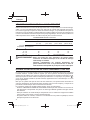
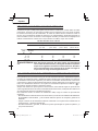
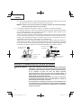
USE PROPER EXTENSION CORD
Make sure your extension cord is in good condition. When using an extension cord, be sure to
use one heavy enough to carry the current your product will draw. An undersized cord will cause
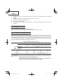
a drop in line voltage resulting in loss of power and overheating. Table shows the correct size to
use depending on cord length and nameplate ampere rating. If in doubt, use the next heavier
gage. The smaller the gage number, the heavier the cord.
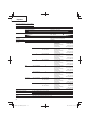
MINIMUM GAGE FOR CORD SETS
Total Length of Cord in Feet (Meter)
0 – 25
(0 – 7.6)
26 – 50
(7.9 – 15.2)
51 – 100
(15.5 – 30.5)
101 – 150
(30.8 – 45.7)
Ampere Rating AWG
More
Than
Not More
Than
0 – 6 18 16 16 14
6 – 10 18 16 14 12
10 – 12 16 16 14 12
12 – 16 14 12 Not Recommended
WARNING: Avoid electrical shock hazard. Never use this tool with a damaged or
frayed electrical cord or extension cord.
Inspect all electrical cords regularly. Never use in or near water or in
any environment where electric shock is possible.

9
English
DOUBLE INSULATION FOR SAFER OPERATION
To ensure safer operation of this power tool, HITACHI has adopted a double insulation design.
“Double insulation” means that two physically separated insulation systems have been used to
insulate the electrically conductive materials connected to the power supply from the outer frame
handled by the operator. Therefore, either the symbol “
” or the words and “Double insulation”
appear on the power tool or on the nameplate.
Although this system has no external grounding, you must still follow the normal electrical
safety precautions given in this Instruction Manual, including not using the power tool in wet
environments.
To keep the double insulation system eff ective, follow these precautions:
* Only HITACHI AUTHORIZED SERVICE CENTER should disassemble or assemble this power
tool, and only genuine HITACHI replacement parts should be installed.
* Clean the exterior of the power tool only with a soft cloth moistened with soapy water and dry
thoroughly.
* Never use solvents, gasoline or thinners on plastic components; otherwise the plastic may
dissolve.
SAVE THESE INSTRUCTIONS
AND
MAKE THEM AVAILABLE TO
OTHER USERS
AND
OWNERS OF THIS TOOL!

10
English
OPERATION AND MAINTENANCE
NOTE: The information contained in this Instruction Manual is designed to assist you
in the safe operation and maintenance of the power tool. Some illustrations in
this Instruction Manual may show details or attachments that diff er from those
on your own power tool.
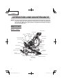
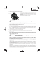
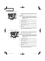
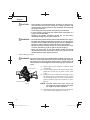
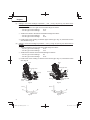
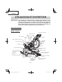
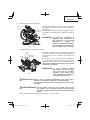
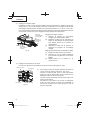
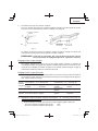
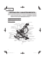
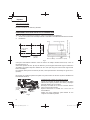
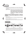
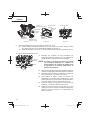
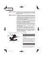
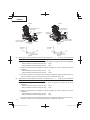
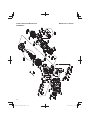
NAME OF PARTS
MODEL C10FSHC
Sub fence (B)
Dust bag
Slide carriage
Holder (A)
Laser marker
Vise assembly
Fence (B)
Base
Gear case
Switch handle
Lower guard
Saw blade
Sub fence (A)
Fence (A)
Table insert
Turntable
Indicator
(For miter scale)
Rotation
direction
Indicator
(For bevel scale)
Motor head
Slide securing knob
Trigger switch
Positive stop
lock button
Miter lock handle
Bevel lock handle
Miter detent
override button
Support rod ass’y
Fig. 1

11
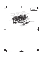
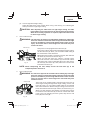
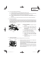
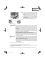
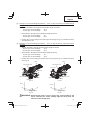
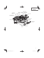
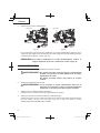
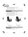
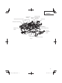
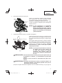
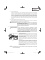
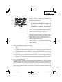
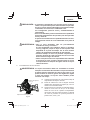
English
Mounting hold
Dust port
Saw blade
Trigger switch
Spindle lock
Set pin (A)
Hinge
Motor ass’y
Stop knob
Locking pin
Bracket (A)
Carriage handle
Laser marker switch
Table insert
LED light switch
Anchor plate
Support rod ass’y
Fig. 2

12
English
SPECIFICATIONS
Item Model C 10FSHC
Motor Type Series commutator motor
Power source Single-phase AC 60Hz
Voltage (Volts) 120
Full-load current (Amp) 15
Laser Marker Maximum output
<5mW CLASS
a Laser Product
Wave length 630 – 660 nm
Laser medium Laser Diode
Applicable saw
blade
Outside Dia. 10" (255 mm)
Hole Dia. 5/8" (15.9 mm)
No load speed 3,200/min
Max.
sawing
dimension
Head Turntable Max. sawing dimension
Miter 0 0 (With anchor plate)
Max. Height
Max. Width
(Without anchor plate)
Max. Height
Max. Width
3-1/2" (89 mm)
11-1/2" (292 mm)
2-1/2" (64 mm)
12-1/2" (318 mm)
0 Left 45°
or
Right 45°
(With anchor plate)
Max. Height
Max. Width
(Without anchor plate)
Max. Height
Max. Width
3-1/2" (89 mm)
8" (204 mm)
2-1/2" (64 mm)
8-3/4" (222 mm)
0 Left 55° (With anchor plate)
Max.Height
Max.Width
(Without anchor plate)
Max.Height
Max.Width
3-1/2" (89 mm)
6-7/8" (176 mm)
2-1/2" (64 mm)
7-1/4" (182 mm)
0 Right 60° (With anchor plate)
Max.Height
Max.Width
(Without anchor plate)
Max.Height
Max.Width
3-1/2" (89 mm)
5-3/4" (146 mm)
2-1/2" (64 mm)
6-1/4" (158 mm)
Bevel Left 45° 0 (With anchor plate)
Max. Height
Max. Width
(Without anchor plate)
Max. Height
Max. Width
1-3/4" (45 mm)
11-1/2" (292 mm)
1-5/8" (41 mm)
12-1/2" (318 mm)
Right 45° 0 (With anchor plate)
Max. Height
Max. Width
(Without anchor plate)
Max. Height
Max. Width
1" (25 mm)
11-1/2" (292 mm)
3/4" (19 mm)
12-1/2" (318 mm)
Compound Left 45° Left 45°
or
Right 45°
(With anchor plate)
Max. Height
Max. Width
(Without anchor plate)
Max. Height
Max. Width
1-3/4" (45 mm)
8" (204 mm)
1-
5/8" (41 mm)
8-3/4" (222 mm)
Right 45° Left 45°
or
Right 45°
(With anchor plate)
Max. Height
Max. Width
(Without anchor plate)
Max. Height
Max. Width
1" (25 mm)
8" (204 mm)
3/4" (19 mm)
8-3/4" (222 mm)
Miter sawing range Left 0° – 55° Right 0° – 60°
Bevel sawing range Left 0° – 48° Right 0° – 48°
Compound sawing range Left (Bevel) 0° – 45°, Left (Miter) 0° – 45°
Right (Bevel) 0° – 45°, Right (Miter) 0° – 45°
Net weight 45.6 lbs. (20.7 kg)
Cord 2 Conductor type cable 6ft. (1.8 m)

13
English
ACCESSORIES
WARNING: Accessories for this power tool are mentioned in this Instruction
Manual.
The use of any other attachment or accessory can be dangerous and
could cause injury or mechanical damage.
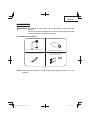
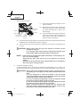
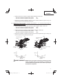
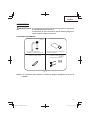
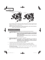
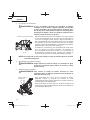
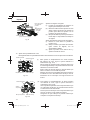
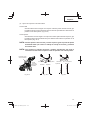
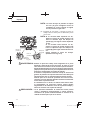
STANDARD ACCESSORIES
3 13 mm Wrench (1 piece)
1 Vise Assembly (1 piece)
For how to use, refer to page 28.
2 Dust bag (1 piece)
For how to use, refer to page 15.
4 Support rod ass’y (2 pieces)
5 mm screw (2 pieces)
Fig. 3
NOTE: Accessories are subject to change without any obligation on the part of the
HITACHI.

14
English
APPLICATIONS
Wood and aluminum sash.
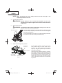
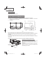
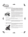
PREPARATION BEFORE OPERATION
Make the following preparations before operating the power tool:
1. Remove all packing materials attached or connected to the tool before attempting to operate
it.
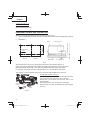
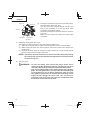
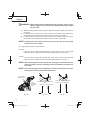
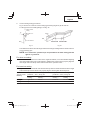
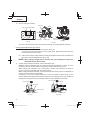
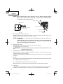
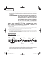
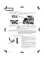
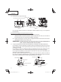
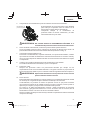
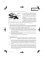
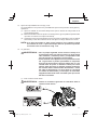
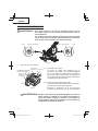
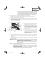
2. Installation
11-39/64"
(295 mm)
11/32" (9 mm)
4 holes
11-27/64"
(290 mm)
10-23/64"
(263 mm)
1" (25 mm) thick bench
Work bench 5/16" (8 mm) nut
5/16" (8mm) boltBase
Fig. 4
Attach the power tool to a level, horizontal work bench in accordance with Fig. 4.
Select 5/16" (8 mm) diameter bolts suitable in length for the thickness of the work bench.
Bolt length should be at least 1-9/16" (40 mm) plus the thickness of the work bench.
For example, use 2-9/16" (65 mm) or larger bolts for a 1" (25 mm) thick work bench.
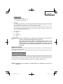
The support rod ass’y attached to the rear of the base helps stabilize the power tool.
Installing the support rod ass’y
Insert one support rod ass’y into the hole located at the
rear of the base and push it in as far as it will go.
Thread the 5 mm screw into the hole next to the
mounting hold.
Firmly tighten the 5 mm screw with a screwdriver.
Repeat the above steps for installing the other support
rod ass’y.
Support
rod ass’y
5 mm
screw
Hole
Fig. 5

15
English
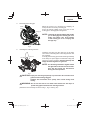
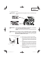
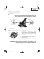
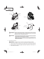
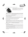
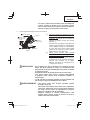
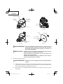
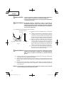
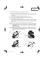
3. Releasing the locking pin
When the power tool is prepared for shipping, its
main parts are secured by a locking pin.
Press the handle slightly down and pull out the
locking pin to disengag the cutting head.
NOTE: Lowering the handle slightly will enable
you to disengage the locking pin more
easily and safely. The lock position
of the locking pin is for carrying and
storage only.
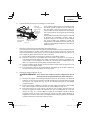
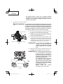
4. Installing the dust bag and vise
Install the dust bag onto the dust port on the miter
saw. Fit the connecting tube of dust bag and the dust
port together.
To empty the dust bag, pull out the dust bag assembly
from dust port. Open zipper on underside of bag and
empty into waste container. Check frequently and
empty the dust bag before it gets full.
NOTE: The dust bag should be angled toward
the right side of the saw for best results.
This will also avoid any interference
during the saw operation.
CAUTION: Empty the dust bag frequently to prevent the duct and the lower
guard from becoming clogged.
Sawdust will accumulate more quickly than normal during bevel
cutting.
WARNING: Do not use this saw to cut and/or sand metals. the hot chips or
sparks may ignite saw dust from the bag material.
(Attach the vise assembly as shown in Fig. 1, Fig. 2 and Fig. 25.)
Pull
Locking pin
Switch
Handle
Fig. 6
Dust port
Dust bag
Fig. 7

16
English
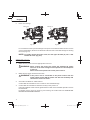
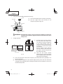
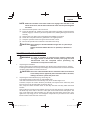
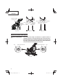
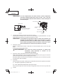
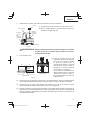
5. Power cord storage
Fig. 8-a Fig. 8-b
Bracket (A)
Bracket (B)
Bracket (A)
Bracket (B)
For convenience and to prevent damage to the power cord when the miter saw is not in use
or is in transportation, there are two brackets at the rear side of the slide carriage for winding
the cord. (Fig. 8-a)
NOTE: To rapidly release the power cord, turn the upper bracket (A) 180°. It will
release the cord. (Fig. 8-b)
BEFORE USING
1. Make sure the power source is appropriate for the tool.
WARNING: Never connect the power tool unless the available AC power
source is of the same voltage as that specifi ed on the nameplate
of the tool.
Never connect this power tool to a DC power source.
2. Make sure the trigger switch is turned OFF.
WARNING: If the power cord is connected to the power source with the
trigger switch turned ON the power tool will start suddenly and
can cause a serious accident.
3. Check the saw blade for visible defects.
Confi rm that the saw blade is free of cracks or other visible damage.
4. Confi rm that the saw blade is attached securely to the power tool.
Using the supplied 13 mm wrench, tighten the 8 mm bolt on the saw blade spindle to secure
the saw blade.
For details, see Fig. 44- a, Fig. 44-b, Fig. 44-c and Fig. 44-d in the section on “SAW BLADE
MOUNTING AND DISMOUNTING”.

17
English
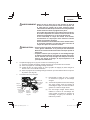
5. Check the lower guard for proper operation.
Lower guard is designed to protect the operator from
coming into contact with the saw blade during operation
of the tool.
Always check that the lower guard moves smoothly
and covers the saw blade properly.
WARNING: NEVER OPERATE THE POWER TOOL if the lower guard does not
function smoothly.
6. Confi rm the position of the spindle lock before using the tool.
After installing the saw blade, confi rm that the spindle lock has been returned to the released
position before using the power tool (see Fig. 2).
7. Check the Power Receptacle.
To prevent overheating, accidental stopping or intermittent operation, confi rm that the
power cord plug fi ts properly in the electrical receptacle and does not fall out after it is
inserted. Repair or replace the receptacle if it is faulty.
8. Confi rm the tool’s power cord is not damaged.
Repair or replace the power cord if an inspection indicates that it is damaged
9. Eye protection
Always wear eye protection with side shields that meets the requirements of ANSI Standard
Z87.1. Ordinary eyeglasses do not provide adequate protection because they do not contain
impact resistant safety glass.
WARNING: Operating the tool without wearing proper eye protection may
result in serious injury.
10. Electric brake
This tool is equipped with an electric brake which will typically stop the blade within 5
seconds after the trigger switch is released.
Occasionally, there will be a delay in the brake engaging which will result in a longer blade
stopping time. On rare occasions, the brake may not engage at all and the saw blade will
coast to a stop.
If the brake fails to engage frequently, depress and release the trigger switch to turn the tool
on and off 4 or 5 times. If the brake still does not engage, have the tool serviced at a Hitachi
authorized service center.
Always confi rm that the saw blade has completely stopped before raising it from the
workpiece.
The brake is not a substitute for a properly functioning lower guard. Check the function of
the lower guard before each use. Serious personal injury may occur if the lower guard does
not move smoothly and cover the blade properly.
Fig. 9
Lower guard

18
English
WARNING: Please be aware of the reaction of the Motor Head (Fig.1) when
the brake is activated. Braking causes the Motor Head to jerk
downward and the user should be prepared for this reaction,
especially when the trigger switch is released before the blade is
completely down. Failure to be familiar with, and prepared for, the
operational characteristics of the tool may cause serious injury.
AFTER CONNECTING THE POWER PLUG TO AN APPROPRIATE AC
POWER SOURCE, CHECK THE OPERATION OF THE TOOL AS FOLLOWS:
11. Trial Run
After confi rming that no one is standing behind, the power tool start and confi rm that no
operating abnormalities exist before attempting a cutting operation.
12. Inspect the rotating stability of the saw blade.
For precise cutting, rotate the saw blade and check for defl ection to confi rm that the blade
is not noticeably unstable; otherwise vibrations might occur and cause an accident.
BEFORE CUTTING
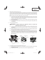
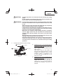
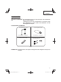
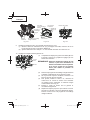
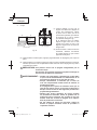
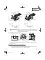
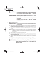
1. Positioning the table insert
Table insert
Table insert
Saw blade
Table insert
Saw blade
Saw blade
4 mm
machine
screw
4 mm
machine
screw
[Right angle cutting]
Fig. 10-a
[Left bevel angle cutting]
Fig. 10-b
[Right bevel angle cutting]
Fig. 10-c
4 mm
machine
screw
Table inserts are installed on the turntable. When shipping the tool from the factory, the
table inserts are so fi xed that the saw blade does not contact them. The burr of the bottom
surface of the workpiece is remarkably reduced, if the table insert is fi xed so that the gap
between the side surface of the table insert and the saw blade will be minimum. Before
using the tool, eliminate this gap in accordance with the following procedure.
(1) Right angle cutting
Loosen the three 4 mm machine screws, then secure the left side table insert and
temporarily tighten the 4 mm machine screws of both ends. Then fi x a workpiece
(about 7-7/8" (200 mm) wide) with the vise assembly and cut it off . After aligning the
cutting surface with the edge of the table insert, securely tighten the 4 mm machine
screws of both ends. Remove the workpiece and securely tighten the 4 mm center
machine screw. Adjust the right hand table insert in the same way.

19
English
(2) Left and right bevel angle cutting
Adjust the table insert in the manner shown in Fig. 10-b and Fig. 10-c following the
same procedure for right angle cutting.
CAUTION: After adjusting the table insert for right angle cutting, the table
insert will be cut to some extent if it is used for bevel angle cutting.
When bevel cutting operation is required, adjust the table insert
for bevel angle cutting.
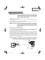
2. Use of sub fence (A)
WARNING: The sub fence (A) must be extended when making any right angle
bevel cut. Failure to extend the sub fence (A) will not allow enough
space for the blade to pass through which could result in serious
injury. At extreme miter or bevel angles the saw blade may also
contact the fence.
This power tool is equipped with a sub fence (A).
In the case of direct angle cutting and left bevel angle cutting,
use the sub fence (A). Then, you can realize stable cutting of
the material with a wide back face.
When right angle cutting, loosen the lock knob, then slide the
sub fence (A) outward, as shown in Fig. 11.
When you slide sub fence (A) outward, if enough space
cannot be secured or the sub fence (A) comes into contact
with other parts of the tool including the motor, fully remove
sub fence (A) from fence (A). Also, make sure to remove the
lock knob from fence (A).
NOTE: When transporting the saw, always secure the sub fence (A) in the
collapsed position and lock it.
3. Use of sub fence (B)
WARNING: The sub fence (B) must be extended when making any left angle
bevel cut. Failure to extend the sub fence (B) will not allow enough
space for the blade to pass through which could result in serious
injury. At extreme miter or bevel angles the saw blade may also
contact the fence.
This power tool is equipped with a sub fence (B). In the case of
direct angle cutting and right bevel angle cutting, use the sub
fence (B). Then, you can realize stable cutting of the material
with a wide back face. When left angle cutting, loosen the lock
knob, then slide the sub fence (B) outward, as shown in Fig. 12.
When you slide sub fence (B) outward, if enough space cannot
be secured or the sub fence (B) comes into contact with other
parts of the tool including the lower guard, fully remove sub
fence (B) from fence (B).
Fig. 11
Fence (A)
Lock knob
Sub fence (A)
Lock knob
Fence (B)
Fig. 12
Sub fence (B)

20
English
NOTE: When transporting the saw, always secure the sub fence (B) in the
collapsed position and lock it.
4. Securing the workpiece
WARNING: Always clamp or vise to secure the workpiece to the fence;
otherwise the workpiece might be thrust from the table and cause
bodily harm.
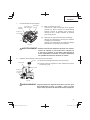
5. Slide carriage system
WARNING: To reduce the risk of injury, return slide carriage to the full rear
position after each crosscut operation.
For chop cutting operations on small workpieces, slide the cutting
head assembly completely toward the rear of the unit and tighten
the slide securing knob.
To cut wide boards up to 305 mm, the slide securing knob must
be loosened to allow the cutting head slide freely.
6. Quick-cam locking lever operation
If miter angles required are NOT one of the
nine positive stops, the miter table can be
locked at any angle between these positive
stops by using the postive stop lock button
and miter lock handle.
Unlock the miter table by lifting up the miter
lock handle, grasp the miter lock handle and
pressing down on the postive stop lock button
to move the table to the desired angle, then
release the postive stop lock button. Press
down on the miter lock handle to lock the table
in position.
Slide securing knob
Fig. 13
Postive stop
lock button
Miter detent
override button
Bevel lock handle
Miter lock handle
Fig. 14
La page charge ...
La page charge ...
La page charge ...
La page charge ...
La page charge ...
La page charge ...
La page charge ...
La page charge ...
La page charge ...
La page charge ...
La page charge ...
La page charge ...
La page charge ...
La page charge ...
La page charge ...
La page charge ...
La page charge ...
La page charge ...
La page charge ...
La page charge ...
La page charge ...
La page charge ...
La page charge ...
La page charge ...
La page charge ...
La page charge ...
La page charge ...
La page charge ...
La page charge ...
La page charge ...
La page charge ...
La page charge ...
La page charge ...
La page charge ...
La page charge ...
La page charge ...
La page charge ...
La page charge ...
La page charge ...
La page charge ...
La page charge ...
La page charge ...
La page charge ...
La page charge ...
La page charge ...
La page charge ...
La page charge ...
La page charge ...
La page charge ...
La page charge ...
La page charge ...
La page charge ...
La page charge ...
La page charge ...
La page charge ...
La page charge ...
La page charge ...
La page charge ...
La page charge ...
La page charge ...
La page charge ...
La page charge ...
La page charge ...
La page charge ...
La page charge ...
La page charge ...
La page charge ...
La page charge ...
La page charge ...
La page charge ...
La page charge ...
La page charge ...
La page charge ...
La page charge ...
La page charge ...
La page charge ...
La page charge ...
La page charge ...
La page charge ...
La page charge ...
La page charge ...
La page charge ...
La page charge ...
La page charge ...
La page charge ...
La page charge ...
La page charge ...
La page charge ...
La page charge ...
La page charge ...
La page charge ...
La page charge ...
La page charge ...
La page charge ...
La page charge ...
La page charge ...
La page charge ...
La page charge ...
La page charge ...
La page charge ...
La page charge ...
La page charge ...
La page charge ...
La page charge ...
La page charge ...
La page charge ...
La page charge ...
La page charge ...
La page charge ...
La page charge ...
La page charge ...
La page charge ...
-
 1
1
-
 2
2
-
 3
3
-
 4
4
-
 5
5
-
 6
6
-
 7
7
-
 8
8
-
 9
9
-
 10
10
-
 11
11
-
 12
12
-
 13
13
-
 14
14
-
 15
15
-
 16
16
-
 17
17
-
 18
18
-
 19
19
-
 20
20
-
 21
21
-
 22
22
-
 23
23
-
 24
24
-
 25
25
-
 26
26
-
 27
27
-
 28
28
-
 29
29
-
 30
30
-
 31
31
-
 32
32
-
 33
33
-
 34
34
-
 35
35
-
 36
36
-
 37
37
-
 38
38
-
 39
39
-
 40
40
-
 41
41
-
 42
42
-
 43
43
-
 44
44
-
 45
45
-
 46
46
-
 47
47
-
 48
48
-
 49
49
-
 50
50
-
 51
51
-
 52
52
-
 53
53
-
 54
54
-
 55
55
-
 56
56
-
 57
57
-
 58
58
-
 59
59
-
 60
60
-
 61
61
-
 62
62
-
 63
63
-
 64
64
-
 65
65
-
 66
66
-
 67
67
-
 68
68
-
 69
69
-
 70
70
-
 71
71
-
 72
72
-
 73
73
-
 74
74
-
 75
75
-
 76
76
-
 77
77
-
 78
78
-
 79
79
-
 80
80
-
 81
81
-
 82
82
-
 83
83
-
 84
84
-
 85
85
-
 86
86
-
 87
87
-
 88
88
-
 89
89
-
 90
90
-
 91
91
-
 92
92
-
 93
93
-
 94
94
-
 95
95
-
 96
96
-
 97
97
-
 98
98
-
 99
99
-
 100
100
-
 101
101
-
 102
102
-
 103
103
-
 104
104
-
 105
105
-
 106
106
-
 107
107
-
 108
108
-
 109
109
-
 110
110
-
 111
111
-
 112
112
-
 113
113
-
 114
114
-
 115
115
-
 116
116
-
 117
117
-
 118
118
-
 119
119
-
 120
120
-
 121
121
-
 122
122
-
 123
123
-
 124
124
-
 125
125
-
 126
126
-
 127
127
-
 128
128
-
 129
129
-
 130
130
-
 131
131
-
 132
132


Hitachi C 10FSHC Safety And Instruction Manual
- Catégorie
- Scies à onglet
- Taper
- Safety And Instruction Manual
dans d''autres langues
- English: Hitachi C 10FSHC
- español: Hitachi C 10FSHC
Documents connexes
-
Hitachi C 10FCD Manuel utilisateur
-
Hitachi 10FCH2 Manuel utilisateur
-
Hitachi C 8FSE Manuel utilisateur
-
Hitachi C10FCH Manuel utilisateur
-
-
-
-
-
-
