GE GDF640HSMSS Guide d'installation
- Catégorie
- Lave-vaisselle
- Taper
- Guide d'installation

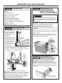
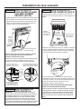
READ CAREFULLY
KEEP THESE INSTRUCTIONS
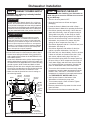
CHECK THE FOLLOWING
Tub trim does not interfere with the door
Dishwasher is square and level at both the top and
bottom of the cabinet opening, with no twisting or
distortion of the tub or door
All 4 legs of the dishwasher are firmly in contact with the
floor
Drain hose is not pinched between the dishwasher and
adjacent cabinets or walls
Tub trim is fully seated on the tub flange
FOR YOUR SAFETY
Read and observe all WARNINGS and CAUTIONS
shown throughout these instructions.
While performing installations described in this
booklet, gloves, safety glasses or goggles should
be worn.
IMPORTANT – Observe all governing codes and
ordinances.
• Note to Installer – Be sure to leave these instructions
for the consumer’s and local inspector’s use.
• Note to Consumer – Keep these instructions with
your Owner’s Manual for future reference.
• Skill Level – Installation of this dishwasher requires
basic mechanical, electrical and plumbing skills.
Proper installation is the responsibility of the
installer. Product failure due to improper installation
is not covered under the GE Appliances Warranty.
See warranty information.
• Completion Time – 1 to 3 Hours. New installations
require more time than replacement installations.
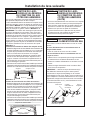
IMPORTANT – The dishwasher MUST be installed to
allow for future removal from the enclosure if service is
required.
Care should be exercised when the appliance is installed
or removed,
to reduce the likelihood of damage to the
power supply cord.
If you received a damaged dishwasher, you should
immediately contact your dealer or builder.
Optional Accessories – See the Owner’s Manual for
available custom panel kits.
Your dishwasher is a water heating appliance.
BEFORE YOU BEGIN
Read these instructions completely and carefully.
31-4000103 09-18 GEA
• Remove all power leading to the appliance from the
circuit breaker or fuse box before beginning installation.
Failure to do so can result in a risk of electrical shock.
•
To reduce the risk of electric shock, fire, or injury to persons,
the installer must ensure that the dishwasher is completely
enclosed at the time of installation.
• The improper connection of the equipment grounding
conductor can result in a risk of electric shock. Check
with a qualified electrician or service representative
if you are in doubt that the appliance is properly
grounded. If house wiring is not 2-wire with ground, a
ground must be by the installer. When house wiring
is aluminum, be sure to use UL-Listed anti-oxidant
compound and aluminum-to-copper connectors.
•
To reduce the risk of electric shock, fire, or injury to persons,
the installer should check to ensure that wires are not pinched
or damaged, the house wiring is attached to the junction box
bracket through a strain relief, and all electrical connections
made at the time of install (wire nuts) are contained inside of
the junction box cover.
WARNING
• Retire todos los conductores de corriente del
electrodoméstico de disyuntor o de la caja del fusible
antes de comenzar con la instalación. Si no cumple con
esto, se podrá producir el riesgo de descargas eléctricas.
• Para reducir el riesgo de descarga eléctrica, incendio
o lesiones a personas, el instalador debe asegurarse
de que el lavaplatos esté completamente cerrado en
el momento de la instalación.
• La conexión inadecuada del conductor de conexión a
tierra del equipamiento puede provocar un riesgo de
descarga eléctrica. Consulte a un electricista calificado
o representante de servicio técnico si tiene dudas
sobre la correcta conexión a tierra del aparato. Si el
cableado doméstico no cuenta con un cable de 2 hilos
con conexión a tierra, un instalador debe realizar una
conexión a tierra. Cuando el cableado doméstico es de
aluminio, asegúrese de usar un compuesto antioxidante
y conectores de aluminio a cobre aprobados por UL.
• Para reducir el riesgo de descarga eléctrica, incendio
o lesiones a personas, el instalador deberá realizar un
control para asegurar que los cables no estén pellizcados
ni dañados, que el cableado del hogar esté conectado a la
ficha de la caja de empalmes a través de un amortiguador
de refuerzo, y que todas las conexiones eléctricas
realizadas en el momento de la instalación (tuercas para
cables) estén dentro de la tapa de la caja de empalmes.
ADVERTENCIA
See your Owner’s Manual for details on how to contact us regarding installation questions
Built-In Dishwashers
Installation
Instructions

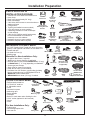
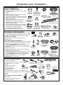
PARTS SUPPLIED IN
INSTALLATION PACKAGE:
• Junction box cover and #10 hex-head screw
• Hose clamp
• Drain hose (approximately 58” long)
• Drain hose hanger
• 2 #8-18 hex head screws to secure brackets to
washer tub frame
• 2 Plug buttons
• Toekick (pre-installed on some models)
• 2 Tub trim pieces (on some models)
• 2 Mounting brackets for wood countertops
or side cabinets
• 2 #8-18 x 5/8” Phillips special head screws,
to secure dishwasher to underside of
countertop or to side cabinets
• Insulation pieces (on some models)
• Literature, samples and/or coupons
TOOLS YOU WILL NEED:
• Phillips-head screwdriver
• 1/4” and 5/16” nutdriver
• 6” Adjustable wrench
• Level
• Carpenter’s square
• Measuring tape
• Safety glasses
• Flashlight
• Bucket to catch water when flushing the line
• 15/16” socket (optional for skid removal)
• Gloves
• Pliers
For New Installations Only:
• Tubing cutter
• Drill and appropriate bits
• Hole saw set
MATERIALS YOU WILL NEED:
• 3/4” GHT (Garden Hose Thread) 90˚ elbow (including
gasket) - with opposite end sized to fit Hot Water Line
• Thread seal tape
• UL-listed wire nuts (3)
• Masking tape
Materials For New Installations Only:
• Air gap for drain hose, if required
• Waste tee for house plumbing, if applicable
• Electrical cable or Power Cord Kit WX09X70910 (5’ 5” long)
or WX09X70911 (7’ 11” long) depending on installation.
• Screw-type hose clamps
• Strain relief for electrical connection
• Hand shut-off valve (recommended)
• Hot Water Line–3/8” minimum, copper tubing (including
ferrule, compression nut) or GE Appliances Part #
WX28X326, flexible braided hose.
• WD24X10065 drain hose (12’ long), if needed.
Installation Preparation
2
Hole Saw Set
Measuring Tape
Tubing Cutter
Drill and Bits
Phillips-Head
Screwdriver
15/16” Socket
1/4” and 5/16”
Nutdriver
Bucket
Flashlight
Gloves
Carpenter’s
Square
Safety Glasses
Level
Hose Clamp
#8 Hex-Head
Mounting Bracket
Screws
Junction
Box Cover
#10
Hex-Head
Junction
Box Screw
1/2" long
#10 hex screw
Mounting
Brackets
#8 Phillips
Special
Head Screws
5/8" long
Literature
Insulation
(on some models)
Tub Trim Pieces
(on some models)
Pliers
Hot
Water
Line
Strain
Relief
Optional
12' Drain Hose
WD24X10065
Drain Hose 10ft.
Hose Clamps
Waste Tee
Electrical Cable
(or Power Cord,
if applicable)
Wire Nuts (3)
GHT 90°Elbow
Hand
Shut-Off
Valve
Air Gap
Coupler for
optional drain hose
Plug
Buttons
Masking Tape
Toekick
Drain Hose Hanger
Thread
Seal Tape
(if applicable)
6” Adjustable
Wrench
Drain Hose

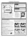
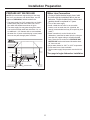
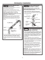
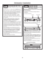
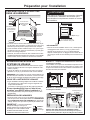
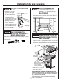
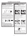
PREPARE DISHWASHER ENCLOSURE
• The rough cabinet opening must be at least 24” deep,
24” wide and approximately 34-1/2” high from floor to
underside of the countertop.
• The dishwasher must be installed so that drain hose is
no more than 12’ in length for proper drainage.
• The dishwasher must be fully enclosed on the top,
sides and back, and must not support any part of the
enclosure.
CLEARANCES:
• When installed into a
corner, allow 2” min.
clearance between
dishwasher and adjacent
cabinet, wall or other
appliances. Allow 25-1/2”
min. clearance from the
front of the dishwasher
for door opening.
34-1/2”+1/4”
Underside of
Countertop
to Floor
This Wall Area
Must be Free
of Pipes and
Wires
Cabinets
Square
and
Plumb
Plumbing and Electric Service
Must Enter Inside This Area
24”
Min.
4”
6”
24”
Min.
33-1/2” to 34-3/4”
Underside of
Countertop
to Floor
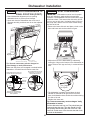
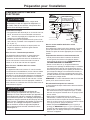
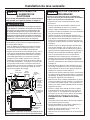
DRAIN REQUIREMENTS
• Follow local codes and ordinances.
• Do not exceed 12’ distance to drain.
• Drain connection height is not to exceed 72” above
bottom of dishwasher.
NOTE : Air gap must be used if waste tee or disposer
connection is less than 18” above floor to prevent siphoning.
DETERMINE DRAIN METHOD
The type of drain installation depends on the following
questions.
• Do local codes or ordinances require an air gap?
• Is waste tee less than 18” above floor?
If the answer to either question is YES, Method 1
MUST be used.
• If the answers are NO, either method may be used.
CABINET PREPARATION
• Drill a 1-1/2” diameter hole in the cabinet wall within
the shaded areas shown in PREPARE DISHWASHER
ENCLOSURE section for the drain hose connection.
The hole should be smooth with no sharp edges.
IMPORTANT – When connecting
drain line to disposer, check to be sure
that drain plug has been removed.
DISHWASHER WILL NOT DRAIN IF
PLUG IS LEFT IN PLACE.
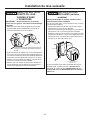
Method 1 – Air Gap with Waste Tee or Disposer
An air gap must be used when required by local codes
and ordinances. The air gap must be installed according
to manufacturer’s instructions.
Tip: Avoid unnecessary service call charges.
Always be sure disposer drain plug has been removed
before attaching dishwasher drain hose to the disposer.
3
Clearance for Door
Opening 2" Minimum
Countertop
Dishwasher
25-1/2"
Remove
Drain
Plug
Installation Preparation
To reduce the risk of electric shock, fire, or injury
to persons, the installer must ensure that the
dishwasher is completely enclosed at the time of
installation.
WARNING
18"
Min.
32"
Min.
Drain Hose Hanger
18"
Min.
32"
Min.
Drain Hose Hanger
Method 2 – “High Drain Loop” with Waste Tee or Disposer
Para reducir el riesgo de descarga eléctrica, incendio
o lesiones a personas, el instalador debe asegurarse
de que el lavaplatos esté completamente cerrado en el
momento de la instalación.
ADVERTENCIA

Installation Preparation
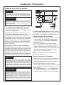
For models equipped with power cord: Do not modify the
plug provided with the appliance; if it will not fit the outlet,
have a proper outlet installed by a qualified technician.
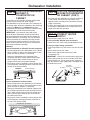
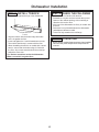
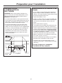
Cabinet Preparation & Wire Routing
• The wiring may enter the opening from either side, rear
or the floor within the shaded area illustrated above
in figure and defined in PREPARE DISHWASHER
ENCLOSURE section.
• Cut a 1-1/2" maximum diameter hole to admit the
electrical cable. Edges of hole should be smooth and
rounded. Permanent wiring connections may pass
through the same hole as the drain hose and hot water
line, if convenient. If cabinet wall is metal, the hole
edge must be covered with a bushing.
NOTE: Power cords with plug must pass through a
separate hole in the cabinet.
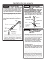
Electrical Connection to Dishwasher
Electrical connection is on the right front of dishwasher.
• For permanent connections the cable must be routed
as shown in figure. Cable must extend a minimum of
24" from the rear wall.
• For power cord connections, install a 3-prong
grounding type receptacle in the sink cabinet rear wall,
6" min. or 18" maximum from the opening, 6" to 18"
above the floor.
• Use only WXO9X70910 (5’ 5” long) or WX09X70911
(7’ 11” long) Dishwasher Power Cord Kit. Do not use
an extension cord or adapter plug with this appliance.
PREPARE ELECTRICAL WIRING
Electrical Requirements
• This appliance must be supplied with 120V, 60 Hz.,
and connected to an individual properly grounded
branch circuit, protected by a 15- or 20-ampere circuit
breaker or time-delay fuse.
• Wiring must be 2 wire with ground and rated for 167°F (75°C).
• If the electrical supply does not meet the above
requirements, call a licensed electrician before proceeding.
Grounding Instructions–Permanent Connection
This appliance must be connected to a grounded metal,
permanent wiring system, or an equipment-grounding
conductor must be run with the circuit conductors and
be connected to the equipment-grounding terminal or
lead on the appliance.
Grounding Instructions–Power Cord Models
This appliance must be grounded. In the event of a malfunction
or breakdown, grounding will reduce the risk of electric shock
by providing a path of least resistance for electric current.
This appliance is equipped with a cord having an equipment-
grounding conductor and a grounding plug. The plug must
be plugged into an appropriate outlet that is installed and
grounded in accordance with all local codes and ordinances.
4
White
18"
6"
24"
from Wall
3"
from
Cabinet
Alternate Receptacle
Location in Adjacent
Cabinet
Ground
Black
1-1/2" Dia. Hole (Max.)
18"
6"
Receptacle
Location
Area
Remove all power leading to the appliance from the
circuit breaker or fuse box before beginning installation.
Failure to do so can result in a risk of electrical shock.
Retire todos los conductores de corriente del electrodoméstico
de disyuntor o de la caja del fusible antes de comenzar con la
instalación. Si no cumple con esto, se podrá producir el riesgo
de descargas eléctricas.
ADVERTENCIA
WARNING
La conexión inadecuada del conductor de conexión a tierra del
equipamiento puede provocar un riesgo de descarga eléctrica.
Consulte a un electricista calificado o representante de servicio técnico
si tiene dudas sobre la correcta conexión a tierra del aparato. Si el
cableado doméstico no cuenta con un cable de 2 hilos con conexión
a tierra, un instalador debe realizar una conexión a tierra. Cuando el
cableado doméstico es de aluminio, asegúrese de usar un compuesto
antioxidante y conectores de aluminio a cobre aprobados por UL.
ADVERTENCIA
The improper connection of the equipment grounding
conductor can result in a risk of electric shock. Check with a
qualified electrician or service representative if you are in doubt
that the appliance is properly grounded. If house wiring is not
2-wire with ground, a ground must be provided by the installer.
When house wiring is aluminum, be sure to use UL-Listed anti-
oxidant compound and aluminum-to-copper connectors.
WARNING

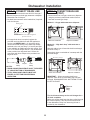
Water Line Connection
• If using a flexible braided supply hose, label
the hose with the installation date to use as
reference. Flexible braided hoses, elbows and
gaskets should be replaced in 5 years.
• Turn off the water supply.
• Install a hand shut-off valve in an accessible
location, such as under the sink. (Optional, but
strongly recommended and may be required by local
codes.)
• Water connection is on the left side of the
dishwasher. Install the hot water inlet line, using no
less than 3/8” copper tubing or a flexible braided
hose. Route the line as shown in PREPARE HOT
WATER LINE section and extend forward at least
19” from rear wall.
• Adjust water heater for 120°F to 140°F temperature.
• Flush water line to clean out debris.
• The hot water supply line pressure must be 20-120
PSI.
Turn page to begin dishwasher installation.
Installation Preparation
PREPARE HOT WATER LINE
NOTE: We recommend copper tubing for the water
line, but if you choose to use flexible hose, use GE
Appliances WX28X326, flexible braided hose.
• The water supply line (3/8” copper tubing or flexible
braided hose) may enter from either side, rear or
floor within the shaded area shown in figure.
• The water supply line may pass through the same
hole as the electrical cable and drain hose. Or, cut
an additional 1-1/2" diameter hole to accommodate
the water line. If power cord with plug is used, water
line must not pass through power cord hole.
6"
4"
Cabinet Face
Shut-off
Valve
2" From Floor
19" From Wall
2"
From
Cabinet
Hot
1-1/2”
Dia.
Hole
5

Toekick
Remove 2
Toekick Screws
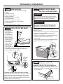
REMOVE TOEKICK
Skip this step if the toekick is not pre-
installed on the unit. On some models the
toekick is packaged separately with the unit.
• Remove the 2 toekick screws and toekick. Set aside
for use in Step 21.
STEP 1
PREPARATION
Locate the items in the installation package:
• Screws
• Junction box cover
• Drain hose and clamp
• Mounting brackets
• Trim pieces (on some models)
• Drain hose hanger
• Insulation pieces (some models)
• Toekick (pre-installed on some models)
• Owner’s Manual
• Product samples and/or coupons
Dishwasher Installation
STEP 3
REMOVE WOOD BASE,
INSTALL LEVELING LEGS
IMPORTANT – Do not kick off wood base!
Damage will occur.
• Move the dishwasher close to the installation location
and lay it on its back. NOTE: Do not place the
dishwasher on its side.
• Remove the 4 leveling legs on the underside of the
wood base with a 15/16” socket wrench.
• Discard base.
• Screw leveling legs back into the dishwasher frame,
approximately 1/2” from frame as shown.
CHECK DOOR BALANCE
• With dishwasher
on the wood
base, check the
door balance
by opening and
closing the door.
• Door is properly
balanced if, when
opened, it self
closes within 20°
from vertical,
stays in position
from 20° to 70°
and falls fully
open beyond 70°.
• If necessary increase or decrease tension as shown.
Latch door and adjust both springs to the same
tension setting to correct balance.
Tip: Make sure door opens and closes smoothly.
Check door opening and closing. If door does not open
easily or falls too quickly, check spring cable routing.
The cable is held in place by “shoulders” on the pulley.
Check to be sure cable has not slipped over the pulley
shoulders and is routed as shown.
Approx
1/2"
STEP 4
6
Door
closes
within
20°
Door stays in
position from
20° to 70°
Door falls fully
open beyond 70°
Side View
STEP 2
Increase
Tension
Decrease
Tension
Side View
Make sure
pulley cable
is within
pulley
shoulders
Front View
Do not remove wood base until you are ready to
install the dishwasher. The dishwasher will tip over
when the door is opened if base is removed.
CAUTION
No quite la base de madera hasta que esté listo
para instalar el lavaplatos. Si se quita la base, el
lavaplatos se volcará cuando se abra la puerta.
PRECAUCIÓN

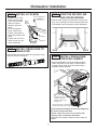
STEP 7
POSITION WATER LINE
AND HOUSE WIRING
• Position water supply line and house wiring on the
floor of the opening to avoid interference with base
of dishwasher and components under dishwasher.
STEP 8
INSTALL DRAIN HOSE,
THROUGH CABINET
• Position dishwasher in front of cabinet opening.
Insert drain hose into the hole in cabinet side. If
a power cord is used, guide the end through a
separate cabinet opening.
Tip: Prevent unnecessary service call charges for
fill, drain or noise concerns.
Position utility lines so they do not interfere with
anything under or behind the dishwasher.
Reposition the insulation blanket over the collar, as
shown.
Dishwasher Installation
Water
Line
House
Wiring
4"
4"
6"
6"
7
STEP 6
INSTALL DRAIN HOSE TO
DRAIN LOOP
Connect drain loop end to drain hose using the screw
clamp as shown in the figure.
STEP 5
INSTALL 90° ELBOW
• Thread 3/4” GHT 90°
elbow onto the water
valve. Ensure rubber
gasket is located
between valve and
elbow.
• Do not overtighten
elbow. Water valve
bracket could bend or
water valve fitting could
break.
• Position the end of the
elbow to face the rear
of the dishwasher.
Water
Valve
Bracket
Fill Hose
Front of dishwasher
90° Elbow
House
Wiring
Power Cord
(If used)
Drain
Hose
Water
Line
Insulation
Blanket
Ensure drain hose is not
twisted or pinched
Maximum drain hose
length is 15'
Do not disconnect or remove high
drain loop from left side of dishwasher
Pull insulation
blanket over
collar

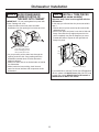
INSTALL TRIM PIECES
(on some models)
Skip this step if trim is not supplied with the
dishwasher.
In this step you will need the trim pieces set aside in
Step 1.
• Position the trim pieces so the lips face toward the
dishwasher door.
• Select a trim piece and press it onto the left side tub
flange. Start with the top edge and press the trim
piece completely onto the tub flange as you move
towards the bottom. Repeat for the right side tub
flange trim piece.
If you would like to order the Trim Kit from GE Appliances
Service, please call 800.GE.Cares (800.432.2737) and
request part number WD08X10094 for BB models or
WD08X10096 for WW or CC models.
Dishwasher Installation
SLIDE DISHWASHER
THREE-FOURTHS OF
THE WAY INTO CABINET
IMPORTANT – Do not push against front panel with
knees. Damage will occur.
•
Grasp the sides of the front panel and slide
dishwasher into the opening a few inches at a time.
• As you proceed, pull the drain hose through the
opening under the sink. Stop pushing when the
dishwasher extends about 6 inches forward of
adjacent cabinets.
• Make sure drain hose is not kinked under or behind
the dishwasher.
• Make certain the house wiring, drain line and
water line do not interfere with components under
dishwasher.
STEP 9
Do not push against
front door panel with
knee. Damage to the
door panel will occur.
8
STEP 10
Top View
Trim
Strip
Trim
Strip
Fully seat to tub flange

Dishwasher Installation
9
INSTALL MOUNTING
BRACKETS
You will need the mounting brackets and 2 #8 hex-
head screws set aside in Step 1.
You must install the mounting brackets onto the
dishwasher tub frame top or sides prior to sliding the
dishwasher into place under the countertop.
Install mounting brackets on top if the
underside of countertop is wood or wood-like
material that accepts screws:
IMPORTANT - After installing brackets and before
closing the dishwasher door, adjust the brackets
by bending them up as needed, so that they do not
contact the top of the dishwasher door and cause
damage.
•
If you are installing the dishwasher under a counter
with a short overhang, the countertop brackets may
extend beyond the edge of the counter. If this is
the case, remove the excess length by repeatedly
bending the brackets at the front notch only until they
break.
Dishwasher
tub frame
#8 Bracket
Screw
Bracket
Bend and break
here after installing if
counter has a short
overhang.
Top Mounting
PUSH DISHWASHER INTO
FINAL POSITION
•
Check the tub insulation blanket, if equipped, to be
sure it is smoothly wrapped around the tub. It should
not be “bunched up” and it must not interfere with
the door springs. If the insulation is “bunched up” or
interfering with the springs, straighten and re-center
the blanket prior to sliding the dishwasher into its
final position.
•
Slide the dishwasher into the final position by
pushing on the sides of the door panel. Do not push
or pull the door in a partially open or closed position
when moving the dishwasher. Do not use a knee or
push on the center of the panel. If you do, damage
to the panel will likely result.
•
The dishwasher is in the final position when the
edges of the front panel are flush with the adjacent
cabinets and the dishwasher is centered in the
cabinet opening. Check that the dishwasher is
squarely positioned in the cabinet opening at both
the top and the bottom of the appliance prior to
mounting to the cabinet.
IMPORTANT – Before opening the dishwasher door,
be certain the edges of the dishwasher door panel are
behind the face of the adjacent cabinet and not up
against the cabinet face. Refer to figure below. If the
dishwasher door is opened when the edge of the door
is against the face of the cabinet, dishwasher door
damage and cabinet damage will occur.
STEP 11
INSTALL MOUNTING
BRACKETS (CONT.)
Install mounting brackets on sides if the
countertop is granite or similar material that
will not accept wood screws:
•
Break off front portion of the tab with pliers at the
location shown prior to attaching to dishwasher.
•
Position the left-hand side bracket as shown. Repeat
with the right bracket.
Bracket
Dishwasher
tub frame
#8 Bracket
screw as
supplied
Side Mounting
Bend and break
here if necessary
Do not screw into
cabinet face frame
Do not pinch
the latch wires
in #8 bracket
screw
Tub trim
STEP 11
STEP 12

Dishwasher Installation
PUSH DISHWASHER INTO
FINAL POSITION (CONT.)
•
Check dishwasher alignment prior to opening
dishwasher door to prevent panel damage.
•
Open and close the dishwasher door to be sure it
operates smoothly, and does not rub on the adjacent
cabinet.
Tip: Prevent unnecessary service charges for
panel damage or wash performance.
Make sure utility lines are not trapped or crushed behind
dishwasher. Crushed lines will restrict water flow.
LEVEL DISHWASHER
IMPORTANT – Dishwasher must be level for proper
dish rack operation, wash performance and door
operation. The dishwasher must be leveled left to right
and front to back. This ensures the dish racks will not
roll in or out on their own, circulation water will flow to
the pump inlet, and the door will close without hitting
the side of the tub.
•
Remove the lower dish rack and place a level on the
door and lower rack track as shown in figure.
•
Adjust the level of the dishwasher by individually
turning the 4 legs on the bottom of the dishwasher as
shown. Ensure all 4 legs are firmly in contact with the
floor.
• The dishwasher is properly leveled when the level
indicator is centered left to right and front to back.
Also, the dishwasher door should close without hitting
the side of the tub.
• Replace the lower rack.
Tip: Prevent unnecessary service charges. Verify
dishwasher is leveled.
Pull the dish racks half way out. They should stay put.
Open and close the door. The door should fit in the
tub opening without hitting the side of the tub. If the
racks roll on their own, or the door hits the side of tub,
re-level the dishwasher.
10
STEP 12 STEP 13
Door Catches
on Cabinet Frame
Correct
Alignmen
t
Incorrect Alignment
will result in door damage
Door
Fits and
Swings
Back
Behind
Cabinet
Frame
Check that tub trim does not
contact the door at all points
Tub trim may be trimmed if
necessary to ensure proper
door operation
Top
View
Handle
Door
Tub trim
Tub frame
Do not allow tub trim to get
trapped by or come into
contact with the door
Top
View
Tub trim
trapped
by door!
Cabinet
Turn Legs
to Adjust

Dishwasher Installation
11
POSITION DISHWASHER,
SECURE TO
COUNTERTOP OR
CABINET
In this step you will need the 2 Phillips special head
screws from the screws set aside in Step 1.
The dishwasher must be secured to the countertop or
the cabinet sides. When the underside of the countertop
is wood, use Method 1. Use Method 2 when the
underside of the countertop is made of a material, such
as granite, that will not accept wood screws.
IMPORTANT – Prevent door panel and control
panel damage. Dishwasher must be positioned so
the front panel and control panel do not contact the
adjacent cabinets or countertop. The unit should be
centered between the 2 cabinets. Mounting screws
must be driven straight and flush. Protruding screw
heads could scratch the door panel or control panel
and interfere with door operation.
Method 1
Secure dishwasher to underside of wood countertop.
• Re-check alignment of the dishwasher in the cabinet.
Refer to Steps 12 and 13. Door panel and/or control
panel must not hit cabinets or countertop.
• Fasten the dishwasher to the underside of the
countertop with the 2 Phillips special head screws.
Refer to figure. Make certain screws are driven
straight and flush to prevent panel damage.
• Plug buttons must be installed to ensure proper door
to tub alignment. Install plug buttons to the side of the
tub well in the holes provided.
Method 2
Secure dishwasher to cabinet sides.
• Recheck alignment of the dishwasher in the cabinet.
Refer to Steps 12 and 13. Door panel and/or control
panel must not hit cabinets or countertop.
• Fasten the dishwasher to the adjacent cabinets with
the 2 Phillips special head screws provided. Refer to
figure. Make certain screws are driven straight and
flush to prevent panel damage. Do not screw into
the cabinet face frame.
• Plug buttons must be installed to ensure proper door
to tub alignment. Install plug buttons to the side of
the tub in the holes provided.
CONNECT WATER
SUPPLY
Connect water supply line to 90° elbow.
If using a flexible braided hose connection:
• Attach nut to 90° elbow using an adjustable wrench.
If using a copper tubing connection:
•
Slide compression nut, then ferrule over end of water
line.
• Insert water line into 90° elbow.
•
Slide ferrule against elbow and secure with
compression nut.
IMPORTANT – Check to be sure that door spring and/
or door spring cable do not rub or contact the fill hose
or water supply line. Test by opening and closing the
door. Re-route the water supply lines if a rubbing noise
or interference occurs.
Solid Surface Countertop
Side Brackets
Plug buttons
Screw
Screw
Compression
Nut
Hot Water
Supply Line
90° Elbow
Ferrule
Bottom Left Side
STEP 14
POSITION DISHWASHER,
SECURE TO COUNTERTOP
OR CABINET (CONT.)
• Re-check that the dishwasher is squarely positioned
in the cabinet at both the top and bottom of the
appliance after mounting to the cabinets/countertop.
Adjust if necessary.
• Confirm all leveling legs are in contact with the floor
to prevent the dishwasher from rocking and ensure
proper door and latch operation
STEP 14
STEP 15
Brackets
Wood Countertop
Brackets
Wood Countertop
Plug buttons
Screw Screw

CONNECT DRAIN LINE
(CONT.)
• Connect drain line to air gap, waste tee or disposer
using the previously determined method. Secure
hose with a screw-type clamp.
Method 1 – Air gap with waste tee or disposer
Method 2 – “High drain loop” with waste tee or
disposer
With this method you will need the drain hose hanger
set aside in Step 1.
Fasten drain hose to underside of countertop with the
provided hanger.
IMPORTANT – When connecting drain line to
disposer, check to be sure that drain plug has been
removed. DISHWASHER WILL NOT DRAIN IF PLUG
IS LEFT IN PLACE.
Tip: Avoid unnecessary service call charges for a
no drain complaint.
Make sure excess drain hose has been pulled through
the cabinet opening. This will prevent excess hose
in the dishwasher cavity from becoming kinked or
crushed by the dishwasher.
Dishwasher Installation
Waste Tee Installation
Disposer Installation
Waste Tee Installation
Disposer Installation
18"
Min.
32"
Min.
05D-1294C
32"
Min.
18"
Min.
05D-1294B
Drain Hose Hanger
Remove
Drain
Plug
12
CONNECT DRAIN LINE
The molded end of the drain hose will fit 5/8” through 1”
diameter inlet ports on the air gap, waste tee or disposer.
• Determine size of inlet port.
• Cut drain hose connector on the marked line, if required,
to fit the inlet port.
• If a longer drain hose is required, replace the
provided user bag drain hose with GE Appliances
service part WD24X10065, a 12’ long hose which
can be connected directly to the drain loop already
attached to the unit (see Step 7). If service part hose
is not available, an additional hose with coupler, ID of
5/8” or 7/8” and no longer than 66”, may be attached
to the provided user bag drain hose. Secure the
connection with hose clamps to the provided user
bag drain hose.
NOTES:
• DRAIN CONNECTION HEIGHT IS NOT TO EXCEED
72” ABOVE BOTTOM OF DISHWASHER.
• TOTAL DRAIN HOSE LENGTH MUST NOT
EXCEED 12 FEET FOR PROPER DRAIN
OPERATION.
1871 Art4
Cutting Line
1"
5/8"
IMPORTANT: Do not cut corrugated
portion of hose
STEP 16 STEP 16
Hose
Clamp
Coupler Hose
Clamp

Dishwasher Installation
13
CONNECT POWER SUPPLY
If a power cord with plug is already installed
proceed to Step 18.
In this step you will need the junction box cover and the
#10 Hex head screw from the screws set aside in Step 1.
• Secure house wiring to the back of the junction box
with a strain relief as shown in the MATERIALS YOU
WILL NEED section.
• Locate the 3 dishwasher wires, (white, black and green)
with the stripped ends coming out of the AC jumper. Use
UL-listed wire nuts of appropriate size to connect incoming
ground to green, white to white and black to black.
• Install the junction box cover using #10 hex head screw.
Check to be sure that wires are not pinched under the
cover and that all wire nuts are inside the cover.
• Make sure that the junction box cover is resting on
the mounting bracket.
To reduce the risk of electric shock, fire, or injury to
persons, the installer should check to ensure that wires
are not pinched or damaged, the house wiring is attached
to the junction box bracket through a strain relief, and
all electrical connections made at the time of install (wire
nuts) are contained inside of the junction box cover.
WARNING
STEP 17
PRETEST CHECKLIST
Review this list after installing your dishwasher to
avoid charges for a service call that is not covered
by your Warranty.
• Check to be sure power is OFF.
• Open door and remove all foam and paper
packaging.
• Locate the Owner’s Manual set aside in Step 1.
• Read the Owner’s Manual for operating instructions.
• Check door opening and closing. If door does not
open and close freely, check for proper routing of
spring cable over pulley. If door drops or closes
when released, adjust spring tension. See Step 2.
• Check to be sure that wiring is secure under the
dishwasher, not pinched or in contact with door
springs or other components. See Step 17.
• Check door alignment with tub. If door hits tub, level
dishwasher. See Step 13.
• Check door alignment with cabinet. If door hits
cabinet, reposition dishwasher. See Step 12.
• Pull lower rack out, about halfway. Check to be sure
it does not roll back or forward on the door. If the
rack moves, adjust leveling legs. See Step 13.
• Check that door spring does not contact water line,
fill hose, wiring or other components. See Step 12.
• Verify water supply and drain lines are not kinked
or in contact with other components. Contact with
motor or dishwasher frame could cause noise.
• Turn on the sink hot water faucet and verify water
temperature. Incoming water temperature must be
between 120°F and 140°F. A minimum of 120°F
temperature is required for best wash performance.
See PREPARE HOT WATER LINE section.
• Add 2 quarts of water to the bottom of the
dishwasher to lubricate the pump seal.
• Turn on water supply. Check for leaks. Tighten
connections if needed.
• Remove protective film if present from the control
panel and door.
• Check that tub trim does not contact the door.
STEP 18
Para reducir el riesgo de descarga eléctrica, incendio
o lesiones a personas, el instalador deberá realizar un
control para asegurar que los cables no estén pellizcados
ni dañados, que el cableado del hogar esté conectado a la
ficha de la caja de empalmes a través de un amortiguador
de refuerzo, y que todas las conexiones eléctricas realizadas
en el momento de la instalación (tuercas para cables) estén
dentro de la tapa de la caja de empalmes.
ADVERTENCIA
NOTE: All ground screws, brackets and wires must remain intact.
Junction
Box Cover
Ground
(Green)
NOTE:
Do not
remove
the
Junction
Box
Bracket.
AC Power
Connector
Junction
Box
Bracket
Black
White
Ground
Screws
Strain
Relief

Dishwasher Installation
14
DISHWASHER WET TEST
• Turn on power supply or plug power cord into outlet,
if equipped.
• Select a cycle to run and push the Start/Reset pad.
• Ensure the door is latched. Dishwasher should start.
• Check to be sure that water enters the dishwasher.
If water does not enter the dishwasher, check to be
sure that water and power are turned on.
• Check for leaks under the dishwasher. If a leak
is found, turn off power at the breaker, and then
tighten water connections. Restore power after leak
is corrected.
• Check for leaks around the door. A leak around
the door could be caused by door rubbing or
hitting against adjacent cabinets. Reposition the
dishwasher if necessary. See Step 12.
• Press and hold the Start/Reset pad for 3 seconds to
cancel the cycle. The unit will begin to drain. Check
drain lines. If leaks are found, turn off power at the
breaker and correct plumbing as necessary. Restore
power after corrections are made. See Steps 6, 7, 8,
9 and 16.
• Open dishwasher door and make sure all of the
water has drained. If not, check that disposer plug
has been removed and/or air gap is not plugged.
Also check drain hose to be sure it is not kinked
underneath or behind dishwasher. See Step 16.
• Press Start/Reset pad once again and run
dishwasher through another cycle. Check for leaks and
correct if required.
• Repeat these steps as necessary.
POSITION SOUND
BARRIER AND INSULATION
(on some models)
Skip this step if the sound barrier is assembled
to the dishwasher.
• Locate the sound insulation package inside the
dishwasher.
• Locate the control box.
• Apply the insulation to the underside of the control
box and flush with its front face as shown.
Insulation shown correctly placed along the bottom
edge of the control box, the dishwasher bottom and
flush with the front face.
If the insulation has an extension piece (on
some models) follow these additional steps:
• Open door all the way, if the door doesn’t stay fully
open, adjust the insulation panel.
• Align the screw holes with the screw holes on the
legs of the dishwasher.
• Ensure vent opening is not blocked by insulation.
STEP 19 STEP 20
Control
Box
Junction Box
Cover
(on some models)
Junction Box
Cover
Vent opening should be properly
aligned with cutout in the insulation

Dishwasher Installation
15
LITERATURE
•
Be sure to leave complete literature package, these Installation
Instructions and product samples and/or coupons with the
consumer.
INSTALL TOEKICK
• Place toekick against the legs of the dishwasher.
• Align the toekick with the bottom edge and make
sure it is against the floor.
• Insert and tighten the 2 toekick attachment screws.
The toekick should stay in contact with the floor.
• When reinstalling the toekick, on models with a sound
barrier, ensure that the bottom edge is flush with
the floor. Any excess material should be tucked up
behind the outer door.
Tip: Reduce sound from under the dishwasher.
Make sure toekick is against floor.
05A-1183C
Attachment
Screws
Toekick
CHECK THE FOLLOWING
• Tub trim does not interfere with the door
• Dishwasher is square and level at both the top and
bottom of the cabinet opening, with no twisting or
distortion of the tub or door
• All 4 legs of the dishwasher are firmly in contact with
the floor
• Drain hose is not pinched between the dishwasher
and adjacent cabinets or walls
• Tub trim is fully seated on the tub flange
STEP 21
STEP 22
STEP 23

16
NOTE: Product improvement is a continuing endeavor. Therefore, materials,
appearance and specifications are subject to change without notice.
Printed in the United States

POUR VOTRE SÉCURITÉ
Veuillez lire et observer toutes les mises en garde
(AVERTISSEMENT et ATTENTION) données dans les
présentes directives.
Pour effectuer l’installation décrite dans les présentes
directives, il faut porter des gants et des lunettes de
sécurité.
IMPORTANT – Observez tous les codes et ordonnances
en vigueur.
• Note à l’installateur – Veuillez laisser les présentes
directives au consommateur pour l’inspecteur local.
• Note au consommateur – Veuillez conserver les
présentes directives avec votre Manuel d’utilisation
pour consultation ultérieure.
• Compétences requises – L’installation de ce
lave-vaisselle exige des compétences de base
en mécanique, en électricité et en plomberie.
L’installateur est responsable de la qualité
de l’installation. Toute défaillance du produit
attribuable à une installation inadéquate n’est
pas couverte par la garantie de GE Appliances.
Reportez-vous à la garantie du produit.
• Durée de l’installation – Entre 1 et 3 heures.
L’installation d’un nouveau lave-vaisselle exige plus de
temps que le remplacement d’un ancien modèle.
IMPORTANT – Le lave-vaisselle DOIT être installé de
manière à ce qu’il puisse être sorti de son emplacement
si des réparations sont nécessaires.
Il importe d'user de prudence lorsque l'appareil est
installé ou déplacé afin de prévenir l'endommagement
du cordon d'alimentation.
Si le lave-vaisselle que vous avez reçu est endommagé,
communiquez immédiatement avec votre détaillant ou
l’entrepreneur en construction.
Accessoires facultatifs – Reportez-vous au Manuel
d’utilisation pour connaître les ensembles pour panneau
décoratif personnalisé offerts.
Votre lave-vaisselle est un appareil qui chauffe l’eau.
VEUILLEZ LIRE ATTENTIVEMENT
CONSERVER CES DIRECTIVES
VÉRIFIEZ LES POINTS SUIVANTS
La moulure de la cuve ne gêne pas la porte
Le lave-vaisselle est d'équerre et de niveau par rapport au
bas et au haut de l'ouverture de l'armoire, sans torsion ni
déformation de la cuve ou de la porte
Les quatre (4) pieds reposent fermement sur le plancher
Le boyau de vidange n'est pas coincé entre le lave-
vaisselle et les armoires ou les murs adjacents
La moulure de cuve repose entièrement contre le bord de
la cuve
31-4000103 09-18 GEA
AVANT DE COMMENCER
Veuillez lire attentivement toutes les directives qui suivent.
• Avant de commencer l’installation, coupez toute
alimentation menant de l’appareil au disjoncteur ou
au fusible. Dans le cas contraire, vous pourriez être
victime d’une décharge électrique.
• Pour réduire les risques de choc électrique,
d’incendie ou de blessures, l’installateur doit
s’assurer que le lave-vaisselle est complètement
encastré au moment de l’installation.
• Un branchement inadéquat du conducteur de
mise à la terre peut présenter des risques de choc
électrique. Si vous n’êtes pas certain que l’appareil
est correctement mis à la terre, consultez un
réparateur ou un électricien qualifié. Si le câblage
électrique de la résidence n’est pas constitué de
deux fils plus un fil de mise à la terre, l’installateur
doit installer un fil de mise à la terre. Si le câblage
électrique de la résidence est en aluminium, utilisez
un agent antioxydant et des connecteurs pour
raccords «aluminium-cuivre» homologués UL.
•
Pour réduire les risques de choc électrique, d’incendie ou
de blessures, l’installateur doit vérifier pour s’assurer que
les fils ne sont pas pliés ou en dommagés, que le câblage
domestique est fixé au support de boîte de connexion par
l’entremise d’un serre-câble et que toutes les connexions
électriques faites au moment de l’installation (capuchons
de connexion) se trouvent à l’intérieur du couvercle de la
boîte de connexion
.
AVERTISSEMENT
Instructions
D’Installation
Lave-vaisselle encastré
Consultez votre Manuel du Propriétaire pour plus de détails sur la façon de nous contacter concernant les
questions d’installation

Préparation pour l’installation
2
PIÈCES FOURNIES
DANS L’EMBALLAGE :
• Couvercle de la boîte de jonction et vis à tête
hexagonale n° 10
• Collier
• Boyau de vidange (147.32 cm/58 po de long)
• Support de tuyau de vidange)
• 2 Vis à tête hexagonale no 8-18 pour fixer les
supports au cadre de la cuve du lave-vaisselle
• 2 Boutons de bouchon
• Plinthe (préinstallée sur certains modèles)
• 2 Moulure de cuve (certains modèles)
• 2 Supports de montage pour comptoirs ou
armoires latérales en bois
• 2 Vis à tête spéciale Phillips n° 8-18 x 15,8 mm
(5/8 po) pour fixer le lave-vaisselle au dessous
du comptoir ou armoires latérales
• Pièces isolantes (certains modèles)
• Documentation, échantillons et(ou) bons
OUTILS NÉCESSAIRES :
• Tournevis cruciforme
• Tournevis à douille de 5/16 po et 1/4 po
• Clé à molette de 15 cm (6 po)
• Niveau
• Équerre de menuisier
• Ruban à mesurer
• Lunettes de sécurité
• Lampe de poche
• Seau pour attraper l’eau lors de la purge du tuyau
• Douille de 15/16 po (optionnelle pour la dépose de la palette)
• Gants
• Pince
Pour une nouvelle installation :
• Coupe-tube
• Perceuse et mèches appropriées
• Jeu de scie-cloche
MATÉRIAUX NÉCESSAIRES :
• Coude90˚de¾poGHT(GardenHoseThread/Filetage
à boyau d’arrosage) (joint d’étanchéité inclus) – Avec bout
opposé dimensionné pour la conduite d’eau chaude
• Ruban pour joints filetés
• Connecteurs vissables homologués UL (3)
• Ruban-cache
Pour une nouvelle installation :
• Coupure anti-refoulement pour le boyau de vidange, si nécessaire
• Raccord en T pour la plomberie de la résidence, s’il y a lieu
• Trousses de câbles électriques ou de cordons
électriques WXO9X70910 (1,65 m (5 pi 5 po de long)) ou
WX09X70911 (2,41 m (7 pi 11 po de long)) uniquement
• Colliers à vis sans fin
• Bague anti-traction pour le raccordement électrique
• Robinet d’arrêt (recommandé)
• Conduite d’eau chaude – 9,5 mm (3/8 po) minimum, tuyau
en cuivre (incluant la bague et l’écrou à compression) ou
la pièce WX28X326 de GE, boyau métallique flexible.
• Boyau de vidange de 3,7 m (12 pi) de long
WD24X10065, si nécessaire
Scie-cloche
Ruban à mesurer
Coupe-tube
Perceuse et
mèches
Tournevis
cruciforme
Douille de 15/16
Tournevis à douille
de 5/16 po et 1/4 po
Seau
Lampe de poche
Gants
Équerre de
menuisier
Lunettes de sécurité
Niveau
Collier
Vis à tête
hexagonale n° 8
pour support de
montage
Couvercle
de la boîte
de jonction
Vis à tête
hexagonale n° 10
de 12,7 mm (1/2
po) de long pour
boîte de jonction
#10 hex screw
Supports de
montage
Vis à tête
spéciale Phillips
n° 8 de 15,8 mm
(5/8 po) de long
Documentation
Isolement
(certains modèles)
Moulure de cuve
(sur certains modèles)
Pince
Boyau de
vidange facultatif
WD24X10065
(Optionnel)
Drain Hose 10ft.
Colliers à vis
sans fin
Raccord
en T
Câble électrique
(ou cordon
d’alimentation, s’il y
a lieu)
Connecteurs
vissables (3)
Coude de 90°
Robinet
d’arrêt
Coupure anti-
refoulement
Optionnel
Raccord pour boyau
de vidange facultatif
Boutons de
bouchon
Ruban-cache
Plinthe
Support de tuyau de
vidange
Ruban pour
joints filetés
(s’il y a lieu)
Clé à molette
de 15 cm (6 po)
Conduite
d’eau
chaude
Boyau de
vidange
Bague
anti-traction

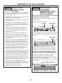
PRÉPARATION DE L’OUVERTURE
DANS LES ARMOIRES
• L’ouverture dans les armoires doit mesurer au moins 61,0 cm (24
po) de largeur et de profondeur, et environ 87,6 cm (34-1/2 po)
de hauteur à partir du plancher jusqu’au-dessous du comptoir.
• Le lave-vaisselle doit être installé de façon à ce que le boyau
de vidange mesure au maximum 3.66 mètres (12 pieds) pour
assurer une vidange adéquate.
• Le dessus, les côtés et l’arrière du lave-vaisselle doivent être
complètement dissimulés à l’intérieur de l’ouverture. Le lave-vaisselle
ne doit soutenir aucune partie de la structure des armoires.
DÉGAGEMENTS:
• Dans le cas d’une installation dans un coin, veuillez prévoir
un dégagement d’au moins 5,1 cm (2 po) entre le lave-
vaisselle et les armoires, le mur ou un électroménager
adjacent. Veuillez prévoir un dégagement d’au moins 65 cm
(25-1/2 po) à l’avant du lave-vaisselle pour l’ouverture de la
porte.
Préparation pour l’installation
3
33-1/2 po to 34-3/4
po du dessous
du comptoir au
plancher
Le mur du fond
doit être exempt
de tuyaux ou
de fils
La partie ombrée est
réservée à la plomberie et
à l’électricité
Armoires à
l’équerre et
d’aplomb
61,0 cm
(24 po) min.
15,2 cm (6 po)
61,0 cm
(24 po) min.
10,1 cm
(4 po)
Clearance for Door
Opening 2" Minimum
Countertop
Dishwasher
25-1/2"
Comptoir
Lave-vaisselle
5,1 cm (2 po) minimum
pour l’ouverture de la porte
65 cm (25-1/2 po)
EXIGENCES RELATIVES AU
SYSTÈME DE VIDANGE
• Veuillez observer les ordonnances et les codes locaux en vigueur.
• Le boyau de vidange doit avoir une longueur maximale de 3.66
mètres (12 pieds).
• Le boyau de vidange ne doit pas être raccordé à une hauteur
dépassant 1,8 m (72 po) au-dessus du bas du lave-vaisselle.
REMARQUE: Il faut installer une coupure anti-refoulement si le
raccord au broyeur à déchets ou au raccord en T se trouve à moins
de 46 cm (18 po) au-dessus du plancher afin d’éviter un siphonage.
CHOIX DE LA MÉTHODE DE VIDANGE
Le type d’installation de vidange dépend des conditions suivantes.
• Les ordonnances ou codes locaux en vigueur exigent-ils une
coupure anti-refoulement?
• Le raccord T se trouve-t-il à moins de 46cm (18po) du plancher?
Si vous répondez OUI à l’une ou l’autre de ces
questions, vous DEVEZ utiliser la méthode n° 1.
• Si vous répondez NON, vous pouvez employer l’une ou l’autre
des méthodes.
PRÉPARATION DES ARMOIRES
• Percez un trou de 3,8 cm (1-1/2 po) de diamètre dans la paroi de
l’armoire qui se trouve dans la partie ombrée de la PRÉPARATION
DE L’OUVERTURE DANS LES ARMOIRES pour le boyau de
vidange. Assurez-vous que l’orifice ne présente pas d’arêtes vives.
IMPORTANT – Lorsque vous branchez
le boyau de vidange à un broyeur à
déchets, assurez-vous d’enlever le bouchon
de vidange. LE LAVE-VAISSELLE NE
POURRA PAS SE VIDER SI VOUS
LAISSEZLEBOUCHONENPLACE.
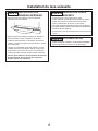
Méthode n° 1 – Coupure anti-refoulement avec raccord en
T ou broyeur à déchets
Il faut installer une coupure anti-refoulement lorsqu’elle est exi-
gée par les ordonnances et les codes locaux en vigueur. Cette
coupure anti-refoulement doit être installée conformément aux
directives données par le fabricant.
Méthode n° 2 – Boucle de vidange élevée avec raccord en
T ou broyeur à déchets
Conseil: Pour éviter des frais de réparation inutiles.
Assurez-vous d’enlever le bouchon de vidange du broyeur à
déchets avant d’y brancher le boyau de vidange du lave-vaisselle.
Pour réduire les risques de choc électrique, d’incendie
ou de blessures, l’installateur doit s’assurer que le
lave-vaisselle est complètement encastré au moment
de l’installation.
AVERTISSEMENT
18"
Min.
32"
Min.
18"
Min.
32"
Min.
Crochet pour boyau de vidange
46 cm
(18 po) min.
82 cm
(32 po)
min.
Crochet pour boyau
de vidange
46 cm
(18 po) min.
82 cm
(32 po)
min.
Remove
Drain
Plug
Enlevez le
bouchon
de vidange

PRÉPARATION DU CÂBLAGE
ÉLECTRIQUE
Alimentation électrique
• Cet appareil doit être alimenté par un courant de 120 V et
60Hz,etbranchéàuncircuitindividuelcorrectement
mis à la terre et protégé par un disjoncteur de 15 ou 20
ampères ou un fusible temporisé.
• Le câble électrique doit posséder deux fils, plus un fil de
mise à la terre, et résister à une température nominale de
75°C(167°F).
• Si votre alimentation électrique ne répond pas à ces
exigences, appelez un électricien agréé avant de
poursuivre l’installation.
Mise à la terre – Branchement permanent
Cet appareil doit être branché à un réseau électrique
permanent mis à la terre. Sinon, il faut installer un
conducteur de mise à la terre avec les conducteurs du
circuit et le brancher à la borne de mise à la terre du
réseau ou au fil de mise à la terre de l’appareil.
Mise à la terre – Modèles dotés d’un cordon
d’alimentation
Cet appareil doit être mis à la terre. En cas de mauvais
fonctionnement ou de défaillance, la mise à la terre réduira
les risques de choc électrique en fournissant au courant
électrique un circuit de moindre résistance. Cet appareil est
doté d’un cordon d’alimentation possédant un conducteur
de mise à la terre et une fiche de mise à la terre. La fiche
doit être branchée dans une mise appropriée, installée et
mise à la terre en conformité avec tous les codes locaux et
ordonnances en vigueur.
Dans le cas des modèles dotés d’un cordon
d’alimentation:
Ne modifiez pas la fiche fournie avec l’appareil; si vous ne
pouvez pas la brancher dans la prise de courant, faites
installer une prise de courant appropriée par un technicien
qualifié.
Préparation des armoires et cheminement des fils
• Les fils peuvent entrer dans l’ouverture du côté droit,
du côté gauche, de l’arrière ou du plancher dans la
partie ombrée de la figure et de la PRÉPARATION DE
L’OUVERTURE DANS LES ARMOIRES.
• Percez un trou de 3,8 cm (1-1/2 po) de diamètre au
maximum pour le passage du câble électrique. Le bord du
trou doit être lisse et arrondi. Les fils électriques pour le
branchement permanent peuvent passer par le même trou
que le boyau de vidange et la conduite d’eau chaude, si
c’est plus pratique. Si le trou est pratiqué dans une paroi
en métal, les bords de l’orifice doivent être recouverts d’un
passe-fils pour protéger les fils.
REMARQUE: Le cordon d’alimentation doté d’une fiche doit
passer par un autre trou dans l’armoire.
Branchement électrique du lave-vaisselle
Le branchement électrique s’effectue du côté avant droit du
lave-vaisselle.
• Dans le cas d’un branchement permanent, le câble doit
êtreacheminédelafaçonindiquéeàlagure.Lecâble
doit avoir une longueur minimale de 61 cm (24 po) à partir
du mur arrière.
• Dans le cas d’un branchement avec un cordon
d’alimentation, installez une prise de courant mise à la
terre à trois broches sur la paroi de l’armoire adjacente,
entre 15 cm (6 po) et 46 cm (18 po) de l’ouverture, et entre
15 cm (6 po) et 46 cm (18 po) du plancher.
• Utilisez uniquement WXO9X70910 (1,65 m (5 pi 5 po
de long)) ou WX09X70911 (2,41 m (7 pi 11 po de long))
Trousse de cordon d’alimentation pour lave-vaisselle.
N’utilisez pas une rallonge électrique ou un adaptateur de
fiche avec cet appareil.
4
Préparation pour l’installation
Zone pour
la prise de
courant
Autre emplacement
possible pour la prise
de courant dans une
armoire adjacente
46 cm (18 po)
46 cm
(18 po)
15 cm (6 po)
15 cm
(6 po)
Trou de 3,8 cm
(1-1/2 po) de dia.
(max.)
7,6 cm (3 po)
des armoires
61 cm (24
po) du mur
Mise à la terre
Noir
Blanc
Avant de commencer l’installation, coupez toute
alimentation menant de l’appareil au disjoncteur ou
au fusible. Dans le cas contraire, vous pourriez être
victime d’une décharge électrique.
AVERTISSEMENT
Un branchement inadéquat du conducteur de
mise à la terre peut présenter des risques de choc
électrique. Si vous n’êtes pas certain que l’appareil est
correctement mis à la terre, consultez un réparateur
ou un électricien qualifié. Si le câblage électrique de la
résidence n’est pas constitué de deux fils plus un fil de
mise à la terre, l’installateur doit installer un fil de mise
à la terre. Si le câblage électrique de la résidence
est en aluminium, utilisez un agent antioxydant et
des connecteurs pour raccords «aluminium-cuivre»
homologués UL.
AVERTISSEMENT
La page est en cours de chargement...
La page est en cours de chargement...
La page est en cours de chargement...
La page est en cours de chargement...
La page est en cours de chargement...
La page est en cours de chargement...
La page est en cours de chargement...
La page est en cours de chargement...
La page est en cours de chargement...
La page est en cours de chargement...
La page est en cours de chargement...
La page est en cours de chargement...
-
 1
1
-
 2
2
-
 3
3
-
 4
4
-
 5
5
-
 6
6
-
 7
7
-
 8
8
-
 9
9
-
 10
10
-
 11
11
-
 12
12
-
 13
13
-
 14
14
-
 15
15
-
 16
16
-
 17
17
-
 18
18
-
 19
19
-
 20
20
-
 21
21
-
 22
22
-
 23
23
-
 24
24
-
 25
25
-
 26
26
-
 27
27
-
 28
28
-
 29
29
-
 30
30
-
 31
31
-
 32
32


GE GDF640HSMSS Guide d'installation
- Catégorie
- Lave-vaisselle
- Taper
- Guide d'installation
dans d''autres langues
- English: GE GDF640HSMSS Installation guide
Documents connexes
Autres documents
-
Maytag MDB9150AWW Installation Instructions Manual
-
Bertazzoni DW24S3IPV Manuel utilisateur
-
-
Bertazzoni DW24T3IPV Manuel utilisateur
-
Heartland HCTTDW-Prev Le manuel du propriétaire
-
 SCS Sentinel 3245060981136 Le manuel du propriétaire
-
Monogram ZKR36R Manuel utilisateur
-
Equator WB 82 Guide d'installation
