Maytag 7MWET3300EQ0 Guide d'installation
- Catégorie
- Sèche-linge électriques
- Taper
- Guide d'installation

27" (69 CM) ELECTRIC WASHER/DRYER
INSTALLATION INSTRUCTIONS
INSTRUCTIONS POUR UINSTALLATION DE LA LAVEUSE/
SI CHEUSE I LECTRIQUE DE 27" (69 CM)
Table of Contents Table des mati_res
WASHER/DRYER SAFETY .......................................................... 1
iNSTALLATiON REQUIREMENTS ............................................... 3
Tools and Parts ..................................................................... 3
LOCATION REQUIREMENTS ...................................................... 5
DIMENSIONS/CLEARANCES ..................................................... 6
DRAIN SYSTEM ........................................................................... 7
ELECTRICAL REQUIREMENTS - U.S.A ..................................... 8
ELECTRICAL REQUIREMENTS - CANADA ............................... 9
REMOVE SHiPPiNG STRAP ...................................................... 10
iNSTALL LEVELING LEGS ......................................................... 10
ELECTRICAL CONNECTION (U.S.A. ONLY) ............................ 11
VENTING ..................................................................................... 17
Venting Requirements ........................................................ 17
Plan Vent System ................................................................ 18
Install Vent System ............................................................. 19
CONNECT DRAIN HOSE ........................................................... 20
CONNECT iNLET HOSES .......................................................... 21
CONNECT VENT ........................................................................ 22
LEVEL WASHER/DRYER ........................................................... 23
COMPLETE iNSTALLATiON CHECKLIST ................................ 24
SLeCURITle DE LA LAVEUSE/SECHEUSE ................................ 25
EXIGENCES D'INSTALLATION ................................................. 27
Outillage et pi_ces ............................................................. 27
EXIGENCES D'EMPLACEMENT .............................................. 29
DIMENSIONS/DISTANCES DE DleGAGEMENT ....................... 30
SYSTEME DE VIDANGE ............................................................ 31
SPleClFICATIONS leLECTRIQUES - CANADA ......................... 32
ENLEVER LA SANGLE D'EXPleDITION .................................... 33
iNSTALLATiON DES PIEDS DE NIVELLEMENT ...................... 33
i_VACUATION ............................................................................. 34
Exigences concernant I'_vacuation ................................. 34
Planification du syst_me d'_vacuation ............................ 35
installation du conduit d'_vacuation ................................ 36
RACCORDEMENT DU TUYAU DE VIDANGE ........................... 37
RACCORDEMENT DES TUYAUX D'ARRIVleE D'EAU ............. 38
RACCORDEMENT DU CONDUIT DqeVACUATION ................. 39
leTABLISSEMENT DE L'APLOMB DE
LA LAVEUSE/SI_CHEUSE .......................................................... 40
LISTE DE VERIFICATION POUR L'ACH_:VEMENT
DE L'INSTALLATION .................................................................. 41
iNSTALLATiON NOTES
Date of purchase:
Date of installation:
installer:
Model number:
Serial number:
NOTES CONCERNANT L'INSTALLATION
Date d'achat :
Date d'installation :
Installateur :
Num_ro de module :
Num_ro de s_rie :
WASHER/DRYER SAFETY
Your safety and the safety of others are very important.
We have provided many important safety messages in this manual and on your appliance. Always read and obey all safety
messages.
This is the safety alert symbol.
This symbol alerts you to potential hazards that can kill or hurt you and others.
All safety messages will follow the safety alert symbol and either the word "DANGER" or "WARNING."
These words mean:
You can be kiUed or seriously injured if you don't immediately
follow instructions.
You can be killed or seriously injured if you don't follow
instructions.
All safety messages will tell you what the potential hazard is, tell you how to reduce the chance of injury, and tell you what can
happen if the instructions are not followed.
W10356098C

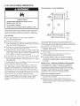
WASHER/DRYER SAFETY
WARNING - ofFifo..
- Clothes dryer installation must be performed by a qualified installer,
= Install the clothes dryer according to the manufacturer's instructions and local codes.
= Do not install a clothes dryer with flexible plastic venting materials or flexible metal
(foil type) duct. if flexible metal duct is installed, it must be of a specific type identified
by the appliance manufacturer as suitable for use with clothes dryers. Flexible venting
materials are known to collapse, be easily crushed, and trap lint. These conditions will
obstruct clothes dryer airflow and increase the risk of fire,
= To reduce the risk of severe injury or death, follow all installation instructions.
= Save these instructions.
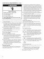
iMPORTANT SAFETY INSTRUCTIONS
WARNING: To reduce the risk of fire, electric shock, or injury to persons when using the washer/dryer, follow basic
precautions, including the following:
[] Read all instructions before using the washer/dryer.
[] Do not place items exposed to cooking oils in your dryer.
Items contaminated with cooking oils may contribute to a
chemical reaction that could cause a load to catch fire.
[] Do not wash or dry articles that have been previously
cleaned in, washed in, soaked in, or spotted with gasoline,
dry-cleaning solvents, other flammable, or explosive
substances as they give off vapors that could ignite or
explode.
[] Do not add gasoline, dry-cleaning solvents, or other
flammable, or explosive substances to the wash water.
These substances give off vapors that could ignite or
explode.
[] Do not allow children to play on or in the washer/dryer.
Close supervision of children is necessary when the
washer/dryer is used near children.
[] Before the washer/dryer is removed from service or
discarded, remove the doors to the washer/dryer
compartments.
[] Do not reach into the washer/dryer if the tub, agitator or
drum is moving.
[] Do not install or store the washer/dryer where it will be
exposed to the weather.
[] Do not tamper with controls.
[] Clean dryer lint screen before or after each load.
[] Under certain conditions, hydrogen gas may be produced
in a hot water system that has not been used for 2 weeks
or more. HYDROGEN GAS iS EXPLOSIVE. ff the hot water
system has not been used for such a period, before using
the washing machine, turn on all hot water faucets and let
the water flow from each for several minutes. This will
release any accumulated hydrogen gas. As the gas is
flammable, do not smoke or use an open flame during
this time.
[] Do not repair or replace any part of the washer/dryer or
attempt any servicing unless specifically recommended in
this Use and Care Guide or in published user-repair
instructions that you understand and have the skills to
carry out.
[] Do not use fabric softeners or products to eliminate static
unless recommended by the manufacturer of the fabric
softener or product.
[] Do not use heat to dry articles containing foam rubber or
similarly textured rubber-like materials.
[] Keep area around the exhaust opening and adjacent
surrounding areas free from the accumulation of lint, dust,
and dirt.
[] The interior of the machine and dryer exhaust vent should
be cleaned periodically by qualified service personnel
[] See "Electrical Requirements" section of the Installation
Instructions booklet for grounding instructions.
SAVE THESE INSTRUCTIONS
2

INSTALLATION REQUIREMENTS
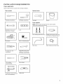
TOOLS AND PARTS
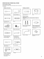
Gather required tools and parts before starting installation.
Tools needed:
@
Flat-blade screwdriver
#2 Phillips screwdriver
Adjustable or open-end
wrench 9/16" (14 mm)
Level
4 ='miR
(102 mm)_
Wood block
Ruler or measuring tape
Optional tools:
Flashlight
Parts supplied:
Bucket
NOTE: Remove parts package from the washer basket.
Check that all parts were included.
Front leveling feet with nuts (2) Shipping strap (Not in parts bag.
See "Remove Shipping Strap.")
Drain hose
Silver double-wire hose clamp
Tin snips (new vent
installations)
Adjustable wrench that
opens to 1" (25 mm) or
hex-head socket wrench
1/4" nut driver Wire stripper
(recommended)
Caulking gun and compound
(new vent installations)
Utility knife

INSTALLATION REQUIREMENTS
TOOLS AND PARTS
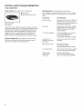
Parts needed: (Not supplied with washer/dryer)
[] Vent clamps
[] Vent elbows and ductwork
Inlet hoses with
flat washers
Check local codes, electrical supply and venting, and read
"Electrical Requirements" and "Venting Requirements" before
purchasing parts. Mobile home installations require metal
exhaust system hardware available for purchase from the
dealer from whom you purchased your washer/dryer. For
further information, please reference the "Assistance or
Service" section of the Washer/Dryer Use and Care Guide.
Optional equipment: (Not supplied with washer/dryer)
Refer to your Use and Care Guide for information about
accessories available for your washer/dryer.
Alternate parts: (Not supplied with washer/dryer)
Your installation may require additional parts. To order, please
refer to toll-free numbers on back page of your Use and Care
Guide.
If you have:
Overhead sewer
Floor drain
You will need:
Standard 20 gal. (76 L) 39" (990 mm)
tall Drain Tub or Utility Sink, Sump
Pump and Connectors (available from
local plumbing suppliers)
Siphon Break Part Number 285320,
Additional Drain Hose Part Number
285702, and Connector Kit Part
Number 285442
1" (25 mm) standpipe 2" (51 mm) diameter to 1" (25 mm)
diameter Standpipe Adapter
Part Number 3363920,
Connector Kit Part Number 285835
Laundry tub or
standpipe taller than
96" (2.4 m)
Drain hose too short
Sump pump system (if not already
available)
Extension Drain Hose
Part Number 285863,
Connector Kit Part Number 285835
Lint clogged drain
Drain Protector Part Number 367031,
Connector Kit Part Number 285835
Water faucets
beyond reach
of fill hoses
2 longer water fill hoses:
6 ft (1.8 m) Part Number 76314,
10 ft (3.0 m) Part Number 350008
4

LOCATION REQUIREMENTS
Explosion Hazard
Keep flammable materials and vapors, such as
gasoline, away from dryer.
Do not install in a garage.
Failure to do so can result in death, explosion, or fire.
Select proper location for your washer to improve performance
and minimize noise and possible "washer walk." Install your
washer in a basement, laundry room, closet, or recessed area.
You will need:
[] A location that allows for proper exhaust installation.
See "Venting Requirements."
[] A separate 30-amp circuit.
[] If you are using a power supply cord, a grounded electrical
outlet located within 2 ft (610 mm) of either side of the washer/
dryer. See "Electrical Requirements."
[] A sturdy floor to support the washer/dryer weight (washer/
dryer, water, and load) of 500 Ibs (226.8 kg).
[] A level floor with a maximum slope of 1" (25 mm) under entire
washer/dryer. Clothes may not tumble properly and automatic
sensor cycles may not operate correctly if washer/dryer is not
level. Installing on carpet is not recommended.
[] A water heater set to deliver 120°F (49°C) water to the washer.
[] Hot and cold water faucets located within 4 ft (1.2 m) of the
hot and cold water fill valves, and water pressure of 5-100 psi
(34.5-689.6 kPa).
The washer/dryer must not be installed or stored in an area where
it will be exposed to water and/or weather.
Do not operate your washer in temperatures at or below 32°F
(0°C). Some water can remain in the washer and can cause
damage in low temperatures. See "Washer/Dryer Care" in the
Washer/Dryer Use and Care Guide for winterizing information.
Do not operate your dryer at temperatures below 45°F (7°C). At
lower temperatures, the dryer might not shut off at the end of an
automatic cycle. This can result in longer drying times.
Check code requirements. Some codes limit, or do not permit,
installation of the washer/dryer in garages, closets, mobile
homes, or sleeping quarters. Contact your local building
inspector.
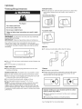
Recessed area or closet installation
48 in.2
(310 cm2)
Front
View
24 in?
(155 cm2)
Closet
door
O
3"
(76mr
The spacing dimensions above are recommended for this
washer/dryer. This washer/dryer has been tested for spacing of
0" (0 mm) clearance on the sides. Recommended spacing should
be considered for the following reasons:
[] Additional spacing should be considered for ease of
installation and servicing.
[] Additional clearances might be required for wall, door, and
floor moldings.
[] Additional spacing on all sides of the washer/dryer is
recommended to reduce noise transfer.
[] For closet installation, with a door, minimum ventilation
openings in the top and bottom of the door are required.
Louvered doors with equivalent ventilation openings are
acceptable.
Mobile Home = Additional Installation Requirements
This washer/dryer is suitable for mobile home installations.
The installation must conform to the Manufactured Home
Construction and Safety Standard, Title 24 CFR, Part 3280
(formerly the Federal Standard for Mobile Home Construction
and Safety, Title 24, HUD Part 280) or the Canadian
Manufactured Home Standard, CAN/CSA-Z240 MH.
Mobile home installations require:
[] Metal exhaust system hardware, which is available for
purchase from your dealer.
[] Special provisions must be made in mobile homes to
introduce outside air into the dryer. The opening (such as a
nearby window) should be at least twice as large as the dryer
exhaust opening.

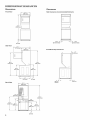
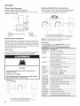
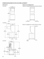
DIMENSIONS/CLEARANCES
Dimensions
713/4,""
(182'; mm]
Front View
88s/4"
(1670 ram)
Side View
(692 ram)
OooooO
1 "
(25 ram)
]
p 73/4"
2!3 ram) _ 26"
(660 ram) I
32V8"
(8!6 ram)
[_32" -_
(8!3 ram)
713/,4""
(1822 ram)
T
34"
(884 mm)
1 H
(25 ram)
Back View
41 t/4"
(1,04 i rara)
(279 ram)
27V4"-_.
(892 ram)
6
Clearances
Side Clearances (recommended/minimum)
/_, _ /h
\/ 0 0 r_ 0 \j
\
1"/0"_ ___ _ 1"/O"
(25 rara/O rara) (25 rara/O ram)
Front/Back/Top Clearances
12"
(305 ram)
(25 turn) (127 ram)
(Closet)

DRAIN SYSTEM
Drain system can be installed using a floor drain, wall standpipe,
floor standpipe, or laundry tub. Select method you need.
Floor standpipe drain system
Minimum diameter for a standpipe drain: 2" (51 mm). Minimum
carry-away capacity: 17 gal. (64 L) per minute. Top of standpipe
must be at least 39" (990 mm) high; install no higher than 96"
(2.4 m) from bottom of washer/dryer. Ifyou must install higher
than 96" (2.4 m), you will need a sump pump system.
Floor drain system
Floor drain system requires a Siphon Break Kit (Part Number
285834), 2 Connector Kits (Part Number 285385), and an
Extension Drain Hose (Part Number 285863) that may be
purchased separately. To order, please see toll-free phone
numbers in your Use and Care Guide. Minimum siphon break:
28" (710 mm) from bottom of washer/dryer. (Additional hoses
may be needed.)
Wall standpipe drain system
See requirements for floor standpipe drain system.
Laundry tub drain system
Minimum capacity: 20 gal. (76 L). Top of laundry tub must be
at least 39" (990 mm) above floor; install no higher than 96"
(2.4 m) from bottom of washer/dryer.
IMPORTANT: To avoid siphoning, no more than 4.5" (114 mm)
of drain hose should be inside standpipe or below the top of
wash tub. Secure drain hose with shipping strap.
J

ELECTRICAL REQUIREMENTS - U.S.A.
Electrical Shock Hazard
Plug into a grounded 3 or 4 prong outlet.
Do not remove ground prong.
Do not use an adapter.
Do not use an extension cord.
Failure to follow these instructions can result in death,
fire, or electrical shock.
[] It is recommended that a separate circuit breaker serving only this
appliance be provided.
[] To minimize possible shock hazard, the cord must be plugged
into a mating, 3- or 4-prong, grounding-type outlet, grounded
in accordance with local codes and ordinances. If a mating
outlet is not available, it is the personal responsibility and
obligation of the customer to have the properly grounded
outlet installed by a qualified electrician.
[] If codes permit and a separate ground wire is used, it is
recommended that a qualified electrician determine that
the ground path is adequate.
[] Check with a qualified electrician if you are not sure the
washer is properly grounded.
[] Do not have a fuse in the neutral or ground circuit.
it is your responsibility:
[] To contact a qualified electrical installer.
[] To be sure that the electrical connection is adequate and in
conformance with the National Electrical Code, ANSVNFPA
70-latest edition and all local codes and ordinances.
A copy of the above code standards can be obtained from:
National Fire Protection Association, One Batterymarch Park,
Quincy, MA 02269.
[] To supply the required 3 or 4 wire, single phase, 120/240 volt,
60 Hz., AC only electrical supply (or 3 or 4 wire, 120/208 volt
electrical supply, if specified on the serial/rating plate) on a
separate 30-amp circuit, fused on both sides of the line. A
time-delay fuse or circuit breaker is recommended. Connect
to an individual branch circuit.
[] Do not use an extension cord.
Electrical Connection
To properly install your washer/dryer, you must determine the
type of electrical connection you will be using and follow the
instructions provided for it here.
[] This washer/dryer is manufactured ready to install with a
3-wire electrical supply connection. The neutral ground wire is
permanently connected to the neutral conductor (white wire)
within the dryer. If the dryer is installed with a 4-wire electrical
supply connection, the neutral ground wire must be removed
from the internal ground connector (green screw), and secured
under the neutral terminal (center or white wire) of the
terminal block. When the neutral ground wire is secured under
the neutral terminal (center or white wire) of the terminal block,
the dryer cabinet is isolated from the neutral conductor.
[] If local codes do not permit the connection of a neutral ground
wire to the neutral wire, see "Optional 3-wire connection" in
the "Electrical Connection" section.
[] A 4-wire power supply connection must be used when the
appliance is installed in a location where grounding through
the neutral conductor is prohibited. Grounding through the
neutral is prohibited for (1) new branch-circuit installations,
(2) mobile homes, (3) recreational vehicles, and (4) areas
where local codes prohibit grounding through the neutral
conductors.
if using a power supply cord:
Use a UL listed power supply cord kit marked for use with
clothes dryers. The kit should contain:
[] A UL listed 30-amp power supply cord, rated 120/240 volt
minimum. The cord should be type SRD or SRDT and be at
least 4 ft (1.22 m) long. The wires that connect to the dryer
must end in ring terminals or spade terminals with upturned
ends.
[] A UL-listed strain relief.
if your outlet
4-wire
receptacle
(14-30R)
looks like this:
Then choose a 4-wire power supply cord with ring
or spade terminals and UL-listed strain relief. The
4-wire power supply cord, at least 4 ft (1.22 m)
long, must have four 10-gauge copper wires and
match a 4-wire receptacle of NEMA Type 14-30R.
The ground wire (ground conductor) may be either
green or bare. The neutral conductor must be
identified by a white cover.
if your outlet
3-wire
receptacle
(10-30R)
looks like this:
Then choose a 3-wire power supply cord with ring
or spade terminals and UL-listed strain relief. The
3-wire power supply cord, at least 4 ft (1.22 m) long,
must have three 10-gauge copper wires and match
a 3-wire receptacle of NEMA Type 10-30R.
if connecting by direct wire:
Power supply cable must match power supply (4-wire or 3-wire)
and be:
[] Flexible armored cable or nonmetallic sheathed copper
cable (with ground wire), covered with flexible metallic
conduit. All current-carrying wires must be insulated.
[] 10-gauge solid copper wire (do not use aluminum).
[] At least 5 ft (1.52 m) long.
8

ELECTRICAL REQUIREMENTS - U.S.A.
GROUNDING iNSTRUCTiONS
For a grounded, cord-connected washer/dryer:
This washer/dryer must be grounded, in the event of a
malfunction or breakdown, grounding will reduce the risk of
electrical shock by providing a path of least resistance for
electric current. This washer/dryer is equipped with a cord
having an equipment=grounding conductor and a grounding
plug. The plug must be plugged into an appropriate outlet
that is properly installed and grounded in accordance with
all local codes and ordinances.
WARNING: Improper connection of the equipment-
grounding conductor can result in a risk of electric shock.
Check with a qualified electrician or serviceman ifyou are
in doubt as to whether the appliance is properly grounded.
Do not modify the plug provided with the appliance - if it will
not fit the outlet, have a proper outlet installed by a qualified
electrician.
For a permanently connected washer/dryer:
This washer/dryer must be connected to a grounded metal,
permanent wiring system, or an equipment grounding
conductor must be run with the circuit conductors and
connected to the equipment-grounding terminal or lead
on the appliance.
SAVE THESE INSTRUCTIONS
ELECTRICAL REQUIREMENTS -
CANADA
Electrical Shock Hazard
Plug into a grounded 4 prong outlet,
Failure to do so can result in death or electrical shock.
it is your responsibility:
[] To contact a qualified electrical installer.
[] To be sure that the electrical connection is adequate and in
conformance with Canadian Electrical Code, C22.1 - latest
edition and all local codes. A copy of above codes standard
may be obtained from: Canadian Standards Association,
178 Rexdale Blvd., Toronto, ON M9W 1R3 CANADA.
[] To supply the required 4-wire, single-phase, 120/240 volt,
60 Hz, AC-only electrical supply on a separate 30-amp circuit,
fused on both sides of the line. A time-delay fuse or circuit
breaker is recommended. Connect to an individual branch
circuit.
[]
This dryer is equipped with a CSA
International Certified Power Cord
intended to be plugged into a standard
14-30R wall receptacle. The cord is 5 ft.
(1.52 m) long. Be sure wall receptacle is
within reach of dryer's final location. 4-wire receptacle
(14-30R)
If using a replacement power supply cord, it is recommended that
you use Power Supply Cord Replacement Part Number 9831317.
For further information, please reference service numbers located
in "Assistance or Service" section of your Use and Care Guide.
GROUNDING iNSTRUCTiONS
[] For a grounded, cord-connected washer/dryer:
This washer/dryer must be grounded. In the event of
malfunction or breakdown, grounding will reduce the risk of
electric shock by providing a path of least resistance for
electric current. This washer/dryer is equipped with a cord
having an equipment-grounding conductor and a grounding
plug. The plug must be plugged into an appropriate outlet
that is properly installed and grounded in accordance with
all local codes and ordinances.
WARNING" Improper connection of the equipment-
grounding conductor can result in a risk of electric shock.
Check with a qualified electrician or service representative
or personnel if you are in doubt as to whether the
washer/dryer is properly grounded. Do not modify the plug
provided with the washer/dryer: if it will not fit the outlet,
have a proper outlet installed by a qualified electrician.
SAVE THESE INSTRUCTIONS

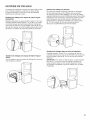
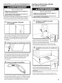
REMOVE SHIPPING STRAP
Excessive Weight Hazard
Use two or more people to move and install washer/dryer.
Failure to do so can result in back or other injury.
To avoid floor damage, set washer/dryer onto cardboard before
moving across floor. Move washer/dryer close to its final location.
Remove strap, hang tag, and pin
Do not cut yellow strap. Pull yellow strap firmly, until completely
removed from washer/dryer. There should be 2 cotter pins on
the end of the shipping strap. Remove the hang tag and pin
from the vent pipe.
INSTALL LEVELING LEGS
Excessive Weight Hazard
Use two or more people to move and install washer/dryer.
Failure to do so can result in back or other injury.
"1, Prepare to install leveling feet
Prop up the front of the washer/dryer
about 4" (102 mm) with a wood block
or similar object that will support the
weight of the washer/dryer. Then screw the Iocknut onto each
foot to within 1" (25 mm) of the foot base.
Check rear leveling legs
Tilt the washer/dryer forward. Move each of the 2 rear legs in
an up-down motion to check the self-adjusting leveling legs
for free movement. This is required for proper leveling. Gently
lower the washer/dryer to the floor.
Cut shipping strap
2, Install front leveling feet
Screw the feet into the threaded holes at
the front corners of the washer/dryer until
the jam nuts touch the washer.
NOTE: Do not tighten the nuts until the washer/dryer is level.
Tilt the washer/dryer back and remove the wood block. Gently
lower the washer/dryer to the floor.
Cut the shipping strap about 16" (406 mm) from the plug end.
Look for the words "CUT HERE." Discard end with cotter pins.
You will use the remaining piece of shipping strap to secure
the drain hose.
10

ELECTRICAL CONNECTION (U.S.A. ONLY)
Power Supply Cord
Fire Hazard
Use a new UL listed 30 amp power supply cord.
Use a UL listed strain relief.
Disconnect power before making electrical connections.
Connect neutral wire (white or center wire) to center
terminal.
Ground wire (green or bare wire) must be connected to
green ground connector.
Connect remaining 2 supply wires to remaining
2 terminals (gold).
Securely tighten all electrical connections.
Failure to do so can result in death, fire, or
electrical shock.
Direct Wire
Fire Hazard
Use 10 gauge copper wire.
Use a UL listed strain relief.
Disconnect power before making electrical connections.
Connect neutral wire (white or center wire) to center
terminal.
Ground wire (green or bare wire) must be connected to
green ground connector.
Connect remaining 2 supply wires to remaining
2 terminals (gold).
Securely tighten all electrical connections.
Failure to do so can result in death, fire, or
electrical shock.
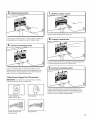
Electrical Connection Options
=1, Choose electrical connection type
Power supply cord 4-wire receptacle
(NEMA Type 14-30R): Go to "4-wire
Power Supply Cord Connection" section.
Then, go to "Venting Requirements."
Power supply cord 3-wire receptacle
(NEMA Type 10-30R): Go to "3-wire
Power Supply Cord Connection" section.
Then go to "Venting Requirements."
4-wire direct connection: Go to "4-wire
Direct Wire Connection" section. Then go
to "Venting Requirements."
2, Remove terminal block cover
B C DA
j
............. I.,_==i.._
r ...... "L"_E
Before you start, disconnect power. Remove hold-down
screw (D) and terminal block cover (A).
3-wire direct connection: Go to "3-wire
Direct Wire Connection" section. Then go
to "Venting Requirements."
NOTE: If local codes do not permit connection of a
cabinet-ground conductor to neutral wire, go to "Optional
3-wire Connection" section. This connection may be
used with either a power supply cord or a direct wire
connection.
A. Terminal block cover
B. External ground conductor screw
C. Center terminal block screw
D. Hold-down screw
E. Neutral ground wire
R Hole below terminal block cover
11

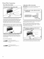
Power Supply Cord Connection
Power Supply Cord Strain Relief
"1, Attach power supply cord strain
relief
I
Remove the screws from a 3/4" (19 mm) UL-listed strain relief
(UL marking on strain relief). Put the tabs of the two clamp
sections (C) into the hole below the terminal block opening
(B) so that one tab is pointing up (A) and the other is pointing
down (D), and hold in place. Tighten strain relief screws just
enough to hold the two clamp sections (C) together.
_, Attach power supply cord
to strain relief
©
Put power supply cord through the strain relief. Be sure that
the wire insulation on the power supply cord is inside the
strain relief. The strain relief should have a tight fit with the
dryer cabinet and be in a horizontal position. Do not further
tighten strain relief screws at this point.
if your outlet looks like this:
Power supply cord 4-wire receptacle
(NEMA Type 14-30R):
Go to "4-Wire Power Supply Cord
Connection" on this page.
Power supply cord 3-wire receptacle
(NEMA Type 10-30R):
Go to "3-Wire Power Supply Cord
Connection" on page 13.
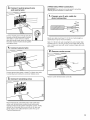
4-Wire Power Supply Cord Connection
iMPORTANT: A 4-wire connection is required for mobile
homes and where local codes do not permit the use of 3-wire
connections.
4-wire receptacle
(NEMA type 14-30R)
4-prong plug
Spade terminals with
upturned ends
Ring terminals
Prepare to connect neutral
ground wire and neutral wire.
Remove center terminal block screw (B). Remove neutral
ground wire (E)from external ground conductor screw (A).
Connect neutral ground wire
and neutral wire
B
C
Connect neutral ground wire (E) and neutral wire (white or
center) (C) of power supply cord under center terminal block
screw (B). Tighten screw.
12

F
A
Connect ground wire (F) (green or bare) of power supply cord
to external ground conductor screw (A).Tighten screw.
I
©
Connect remaining wires to outer terminal block screws.
Tighten screws. Finally, reinsert tab of terminal block cover
into slot of dryer rear panel. Secure cover with hold-down
screw. Now, go to "Venting Requirements."
3=Wire Power Supply Cord Connection
iMPORTANT: Use where local codes permit connecting
cabinet-ground conductor to neutral wire.
3-wire receptacle
(NEMA type 10-30R)
3-prong plug
\ \
J---__jiS
©
Remove center terminal block screw (B).
2, Connect neutral wire
B
C
I
Connect neutral wire (white or center) (C) of power supply cord
to center terminal block screw (B). Tighten screw.
3. Connect remaining wires
Connect remaining wires to outer terminal block screws.
Tighten screws. Finally, reinsert tab of terminal block cover
into slot of dryer rear panel. Secure cover with hold-down
screw. Now, go to "Venting Requirements."
Spade terminals with
upturned ends
Ring terminals
13

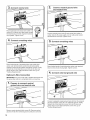
Direct Wire Connection
Direct Wire Strain Relief
"1, Attach direct wire strain relief
I
A
Unscrew the removable conduit connector (A) and any
screws from a 3/4" (19 mm) UL listed strain relief (UL marking
on strain relief). Put the threaded section of the strain relief
(C) through the hole below the terminal block opening (B).
Reaching inside the terminal block opening, screw the
removable conduit connector (A) onto the strain relief threads.
2, Attach direct wire cable to strain relief
I
©
4-Wire Direct Wire Connection
iMPORTANT: A 4-wire connection is required for mobile
homes and where local codes do not permit 3-wire
connections.
f
"1, Prepare your 4-wire cable for direct
connection
(127
Direct wire cable must have 5 ft. (1.52 m) of extra length so
washer/dryer may be moved if needed.
Strip 5" (127 mm) of outer covering from end of cable,
leaving bare ground wire at 5" (127 mm). Cut 11/2"(38 mm)
from remaining 3 wires. Strip insulation back 1" (25 mm).
Shape ends of wires into hooks.
Put direct wire cable through the strain relief. The strain
relief should have a tight fit with the dryer cabinet and be in
a horizontal position. Tighten strain relief screw against the
direct wire cable.
if your wiring looks like this:
4-wire direct connection:
Go to "4-Wire Direct Connection" on
this page.
Remove center terminal block screw (B). Remove neutral
ground wire (E) from external ground conductor screw (A).
3-wire direct connection:
Go to "3-Wire Direct Connection"
on
page 15.
14

3. co_eot neutral ground wire
and neutral wire
I
B
j -E
c
Connect neutral ground wire (E) and place
hooked end (hook facing right) of neutral
wire (white or center wire) (C) of direct
wire cable under center screw of terminal
block (B). Squeeze hooked ends together
and tighten screw.
@
3=Wire Direct Wire Connection
iMPORTANT: Use where local codes permit connecting
cabinet-ground conductor to neutral wire.
f
1, Prepare your 3=wire cable for
direct connection
Direct wire cable must have 5 ft. (1.52 m) of extra length so
washer/dryer may be moved if needed.
Strip 31/2'' (89 mm) of outer covering from end of cable. Strip
insulation back 1" (25 mm). If using 3-wire cable with ground
wire, cut bare wire even with outer covering. Shape wire ends
into hooks.
Connect ground wire (green or bare) (F) of direct wire cable
to external ground conductor screw (A). Tighten screw.
Remove center terminal block screw (B).
Place hooked ends of remaining direct wire cable wires
under outer terminal block screws (hooks facing right).
Squeeze hooked ends together and tighten screws. Finally,
reinsert tab of terminal block cover into slot of dryer rear
panel. Secure cover with hold-down screw. Now, go to
"Venting Requirements."
15

_3
, Connect neutral wire
@
Place hooked end of neutral wire (white or
center) (C) of direct wire cable under center
terminal block screw (B). Squeeze hooked
end together. Tighten screw.
4, Connect remaining wires
I
I
©
Place hooked ends of remaining direct wire cable wires
under outer terminal block screws (hooks facing right).
Squeeze hooked ends together and tighten screws. Finally,
reinsert tab of terminal block cover into slot of dryer rear
panel. Secure cover with hold-down screw. Now, go to
"Venting Requirements."
Optional 3-Wire Connection
iMPORTANT: You must verify with a qualified electrician that
this grounding method is acceptable before connecting.
"1, Prepare to connect neutral
ground wire and neutral wire
Remove center terminal block screw (B). Remove neutral
ground wire (E) from external ground conductor screw (A).
Connect neutral ground wire
and neutral wire
Connect neutral ground wire (E)and neutral wire (white or
center wire) (C) of power supply cord or cable under center
terminal block screw (B). Tighten screw.
3=Connect remaining wires
Place hooked ends of remaining wires under outer terminal
block screws (hooks facing right). Tighten screws.
_4= Connect external ground wire
Connect a separate copper ground wire (G)from the external
ground conductor screw (A) to an adequate ground. Finally,
reinsert tab of terminal block cover into slot of dryer rear
panel. Secure cover with hold-down screw. Now, go to
"Venting Requirements."
16

VENTING
Venting Requirements
Fire Hazard
Use a heavy metal vent,
Do not use a plastic vent.
Do not use a metal foil vent.
Failure to follow these instructions can result in death
or fire.
WARNING: To reduce the risk of fire, this dryer MUST BE
EXHAUSTED OUTDOORS.
IMPORTANT: Observe all governing codes and ordinances.
Dryer exhaust must not be connected into any gas vent,
chimney, wall, ceiling, attic, crawlspace, or a concealed space
of a building. Only rigid or flexible metal vent shall be used for
exhausting.
]
(102 ram)
{
4" (102 mm) heavymetal exhaust vent
[] Only a 4" (102 mm) heavy metal exhaust vent and clamps may
be used.
[] Do not use plastic or metal foil vent.
Rigid metal vent:
[] Recommended for best drying performance and to avoid
crushing and kinking.
Flexible metal vent: (Acceptable only ifaccessible to clean)
[] Must be fully extended and supported in final dryer location.
[] Remove excess to avoid sagging and kinking that may result
in reduced airflow and poor performance.
[] Do not install in enclosed walls, ceilings, or floors.
[] The total length should not exceed 73/4ft. (2.4 m).
NOTE: If using an existing vent system, clean lint from entire
length of the system and make sure exhaust hood is not
plugged with lint. Replace plastic or metal foil vents with rigid
metal or flexible metal vents. Review "Vent System Chart" and,
if necessary, modify existing vent system to achieve best drying
performance.
Exhaust hoods:
[] Must be at least 12" (305 ram) from ground or any object that
may obstruct exhaust (such as flowers, rocks, bushes, or
snow).
Recommended Styles:
Louvered hood
Acceptable Style:
Box hood
Angled hood
Elbows:
[] 45° elbows provide better airflow than 90° elbows.
Bet
Clamps:
[] Use clamps to seal all joints.
[] Exhaust vent must not be connected or secured with screws
or other fastening devices that extend into interior of duct
and catch lint. Do not use duct tape.
improper venting can cause moisture and lint to collect
indoors, which may result in:
[] Moisture damage to woodwork, furniture, paint, wallpaper,
carpets, etc.
[] Housecleaning problems and health problems.
See "Venting Kits" for more information.
17

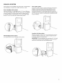
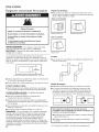
VENTING
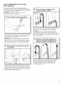
Plan Vent System
Recommended exhaust installations
Typical installations vent the washer/dryer from the rear. Other
installations are possible.
A
c I_Lj
E
G
A. Dryer E. Elbow
B. Rigid metal or flexible metal vent R Clamps
C. Clamps G. Elbow
D. Wall H. Exhaust hood
Optional exhaust installations:
This washer/dryer can be converted to exhaust out the right or
left side. To convert the washer/dryer, use Side Exhaust Kit Part
Number 279823. Ifyour washer/dryer was previously exhausted
from the right or left side, it can be converted to rear exhaust by
using standard offset connections. To cover the hole in the side,
one of the following plugs can be added:
692790 (white)
3977784 (biscuit)
Follow the instructions in the kit to install. Kits are available from
the dealer from whom you purchased your washer/dryer.
Fire Hazard
Cover unused exhaust holes with a manufacturer's
exhaust cover kit.
Contact your local dealer.
Failure to follow these instructions can result in death,
fire, electrical shock, or serious injury.
18
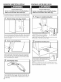
A B C
A. Standard rear offset exhaust installation
B. Rear exhaust for offset close-clearance connection
C. Left- or right-side exhaust installation
Alternate installations for close clearances
Venting systems come in many varieties. Select the type best
for your installation. Three close-clearance installations are
shown. Refer to the manufacturer's instructions.
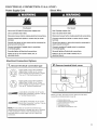
.................. !:::::::::::::::i ....g::::::::::::::'
:i
L",,,d"................ ",,,:.................. ",,,..................
A B C
A. Loop system with standard elbows
B. Loop system with one offset and one standard elbow
C. Ventsystem with one periscope (2" [51 mm] clearance)
NOTE: The following kits for close-clearance alternate
installations are available for purchase.
Venting Kits
For more information, call 1-800-901-2042, or visit us
at www.applianceaccessories.com. In Canada, call
1-800-807-6777 or visit us at www.whirlpoolparts.ca.
Part Number Descriptions
4396028 Over-the-Top Installation
4396037 0" (0 mm) to 18" (457 mm)
Metal vent periscope (For use with dryer vent to
wall vent mismatch)
4396011 18" (457 mm) to 29" (737 mm)
Metal vent periscope (For use with dryer vent to
wall vent mismatch)
4396014 29" (737 mm) to 50" (1.27 m)
Metal vent periscope (For use with dryer vent to
wall vent mismatch)
4392892 In-Wall metal DuraVent TM Periscope
279818 4-way vent kit - white
W10186596 4-way vent kit - universal grey
4396028 Sure Connect TM venting kit
(over-the-top installation)
4396009RP 5' Universal connect vent, flexible dryer venting
4396010RP 6' SecureConnect TM vent, flexible dryer venting
4396013RB Dryer vent installer's kit
4396033RP 5' flexible dryer venting with clamps
4396727RP 8' flexible dryer venting with clamps
4396004 Dryer offset elbow
4396005 Wall offset elbow
4396006RW DuraSafe TM close elbow
4396007RW Through-the-wall vent cap
4396008RP 4" steel dryer venting clamps- 2 pack
8212662 Flush mounting Iouvered vent hood 4"

Specialprovisionsfor mobilehome installations:
The exhaust vent must be securely fastened to a noncombustible
portion of the mobile home structure and must not terminate
beneath the mobile home. Terminate the exhaust vent outside.
Determine vent path:
[] Select route that will provide straightest and most direct
path outdoors.
[] Plan installation to use fewest number of elbows and turns.
[] When using elbows or making turns, allow as much room
as possible.
[] Bend vent gradually to avoid kinking.
[] Use as few 90° turns as possible.
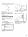
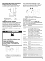
Determine vent length and elbows needed for best
drying performance:
[] Use following "Vent System Chart" to determine type of vent
material and hood combinations acceptable to use.
NOTE: Do not use vent runs longer than those specified
in "Vent System Chart." Exhaust systems longer than those
specified will:
[] Shorten life of dryer.
[] Reduce performance, resulting in longer drying times
and increased energy usage.
The "Vent System Chart" provides venting requirements that
will help achieve best drying performance.
Vent System Chart
Number of Type Box/Iouvered
90 °turns of vent hoods
or elbows
0 Rigid metal
1 Rigid metal
2
Rigid metal
37 ft. (11.3 m)
32 ft. (9.7 m)
24 ft. (7.3 m)
Angled
hoods
35 ft. (10.7 m)
27 ft. (8.2 m)
19 ft. (5.8 m)
NOTE: Side exhaust installations have a 90 ° turn inside the
dryer. To determine maximum exhaust length, add one 90°
turn to the chart.
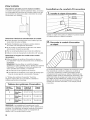
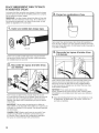
Install Vent System
"1, Install exhaust hood
m_
q _ 12""rain.
(305 ram)
Install exhaust hood and use caulking compound to seal
exterior wall opening around exhaust hood.
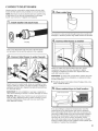
2, Connect vent to exhaust hood
;;;;;;;;;;;;;;;;;;;;;;;;;;;;;
Vent must fit over the exhaust hood. Secure vent to exhaust
hood with 4" (102 mm) clamp. Run vent to dryer location using
straightest path possible. Avoid 90° turns. Use clamps to seal
all joints. Do not use duct tape, screws, or other fastening
devices that extend into interior of vent to secure vent,
because they can catch lint.
i,i!
ill
19

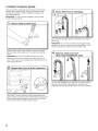
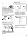
CONNECT DRAIN HOSE
Proper connection of the drain hose protects your floors from
damage due to water leakage. To keep the drain hose from
coming off or leaking, it must be installed according to the
following instructions:
IMPORTANT: To ensure proper installation, this procedure
must be followed exactly.
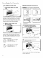
, Attach clamp to drain hose
Check the drain hose to see whether it is the proper length.
Wet the inside of the straight end of the drain hose with tap
water.
IMPORTANT: Do not use any lubricant other than water.
Squeeze ears of the silver double-wire clamp with pliers to
open. Place clamp over the straight end of the drain hose 1/4"
(6.4 mm) from the end.
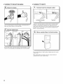
Attach drain hose to drain connector
Place drain hose in standpipe
Place hose into standpipe (shown in picture) or over side of
laundry tub.
IMPORTANT: 4.5" (114 mm) of drain hose should be inside
standpipe; do not force excess hose into standpipe or lay on
bottom of laundry tub. Drain hose form must be used.
"4, Remove drain hose form
(floor drain installations only}
I
For floor drain installations, you will need to remove the drain
hose form from the end of the drain hose. You may need
additional parts with separate directions. See "Tools and Parts."
Open clamp. Twist hose back and forth while pushing onto
drain connector on the side of the washer/dryer. Continue until
hose contacts the ribbed stops on the cabinet. Place clamp
over the area marked "CLAMR" Release clamp.
20
La page est en cours de chargement...
La page est en cours de chargement...
La page est en cours de chargement...
La page est en cours de chargement...
La page est en cours de chargement...
La page est en cours de chargement...
La page est en cours de chargement...
La page est en cours de chargement...
La page est en cours de chargement...
La page est en cours de chargement...
La page est en cours de chargement...
La page est en cours de chargement...
La page est en cours de chargement...
La page est en cours de chargement...
La page est en cours de chargement...
La page est en cours de chargement...
La page est en cours de chargement...
La page est en cours de chargement...
La page est en cours de chargement...
La page est en cours de chargement...
La page est en cours de chargement...
La page est en cours de chargement...
La page est en cours de chargement...
La page est en cours de chargement...
-
 1
1
-
 2
2
-
 3
3
-
 4
4
-
 5
5
-
 6
6
-
 7
7
-
 8
8
-
 9
9
-
 10
10
-
 11
11
-
 12
12
-
 13
13
-
 14
14
-
 15
15
-
 16
16
-
 17
17
-
 18
18
-
 19
19
-
 20
20
-
 21
21
-
 22
22
-
 23
23
-
 24
24
-
 25
25
-
 26
26
-
 27
27
-
 28
28
-
 29
29
-
 30
30
-
 31
31
-
 32
32
-
 33
33
-
 34
34
-
 35
35
-
 36
36
-
 37
37
-
 38
38
-
 39
39
-
 40
40
-
 41
41
-
 42
42
-
 43
43
-
 44
44


Maytag 7MWET3300EQ0 Guide d'installation
- Catégorie
- Sèche-linge électriques
- Taper
- Guide d'installation
dans d''autres langues
Documents connexes
-
Maytag WET3300XQ Installation Instructions Manual
-
-
Maytag MET3800TW2 Guide d'installation
-
Maytag HybridCare YWED99HEDC Le manuel du propriétaire
-
Maytag MDG18PDAW Installation Instructions Manual
-
-
-
-
Maytag MGT3800XW Installation Instructions Manual
-
Autres documents
-
Whirlpool WET4027HW0 Guide d'installation
-
Crosley YCED8990XW1 Guide d'installation
-
Whirlpool WED7990FW Le manuel du propriétaire
-
-
Whirlpool WHD862CHC Guide d'installation
-
-
-
LG WKEX200HBA Le manuel du propriétaire
-
Kenmore 11081422510 Le manuel du propriétaire
-