12
NOTE: This refrigerator is intended for use in a location where
the temperature ranges from a minimum of 55°F (13°C) to a
maximum of 110°F (43°C). The preferred room temperature
range for optimum performance, which reduces electricity usage
and provides superior cooling, is between 60°F (15°C) and 90°F
(32°C). It is recommended that you do not install the refrigerator
near a heat source, such as an oven or radiator.
Electrical Requirements
Before you move your refrigerator into its nal location, it is
important to make sure you have the proper electrical connection.
If the supply cord is damaged, it must be replaced by the
manufacturer or its service agent or a similarly qualied person.
Do not use a cord that shows cracks or abrasion damage along
its length or at either the plug or connector end.
Recommended Grounding Method
A 115 V, 60 Hz, AC only 15 or 20 A fused, grounded electrical
supply is required. It is recommended that a separate circuit
serving only your refrigerator and approved accessories be
provided. Use an outlet that cannot be turned off by a switch. Do
not use an extension cord.
NOTE: Before performing any type of installation, cleaning, or
removing a light bulb, turn off Cooling, and then disconnect the
refrigerator from the electrical source. When you have nished,
reconnect the refrigerator to the electrical source and turn on
Cooling. See “Using the Control(s).”
Water Supply Requirements
A cold water supply with water pressure between 35 and 120 psi
(241 and 827 kPa) is required to operate the water dispenser and
ice maker. If you have questions about your water pressure, call a
licensed, qualied plumber.
NOTE: If the water pressure is less than what is required, the ow
of water from the water dispenser could decrease or ice cubes
could be hollow or irregular shaped.
Reverse Osmosis Water Supply
IMPORTANT: The pressure of the water supply coming out of
a reverse osmosis system going to the water inlet valve of the
refrigerator needs to be between 35 and 120 psi
(241 and 827 kPa).
If a reverse osmosis water ltration system is connected to your
cold water supply, the water pressure to the reverse osmosis
system needs to be a minimum of 40 to 60 psi (276 to 414 kPa).
■ Check to see whether the sediment lter in the reverse
osmosis system is blocked. Replace the lter if necessary.
■ Allow the storage tank on the reverse osmosis system to rell
after heavy use. The tank capacity could be too small to keep
up with the requirements of the refrigerator.
NOTE: Faucet-mounted reverse osmosis systems are not
recommended.
■ If your refrigerator has a water lter, it may further reduce
the water pressure when used in conjunction with a reverse
osmosis system. Remove the water lter. See “Water Filtration
System.”
If you have questions about your water pressure, call a licensed,
qualied plumber.
Connect the Water Supply
Read all directions before you begin.
IMPORTANT:
■ Connect to potable water supply only.
■ Plumbing shall be installed in accordance with the
International Plumbing Code and any local codes and
ordinances.
■ The gray water tubing on the back of the refrigerator (which
is used to connect to the household water line) is a PEX
(cross-linked polyethylene) tube. Copper and PEX tubing
connections from the household water line to the refrigerator
are acceptable and will help avoid off-taste or odor in your ice
or water. Check for leaks.
If PEX tubing is used instead of copper, we recommend the
following Part Numbers:
W10505928RP (7 ft [2.14 m] jacketed PEX),
8212547RP (5 ft [1.52 m] PEX), or
W10267701RP (25 ft [7.62 m] PEX).
Install tubing only in areas where temperatures will remain above
freezing.
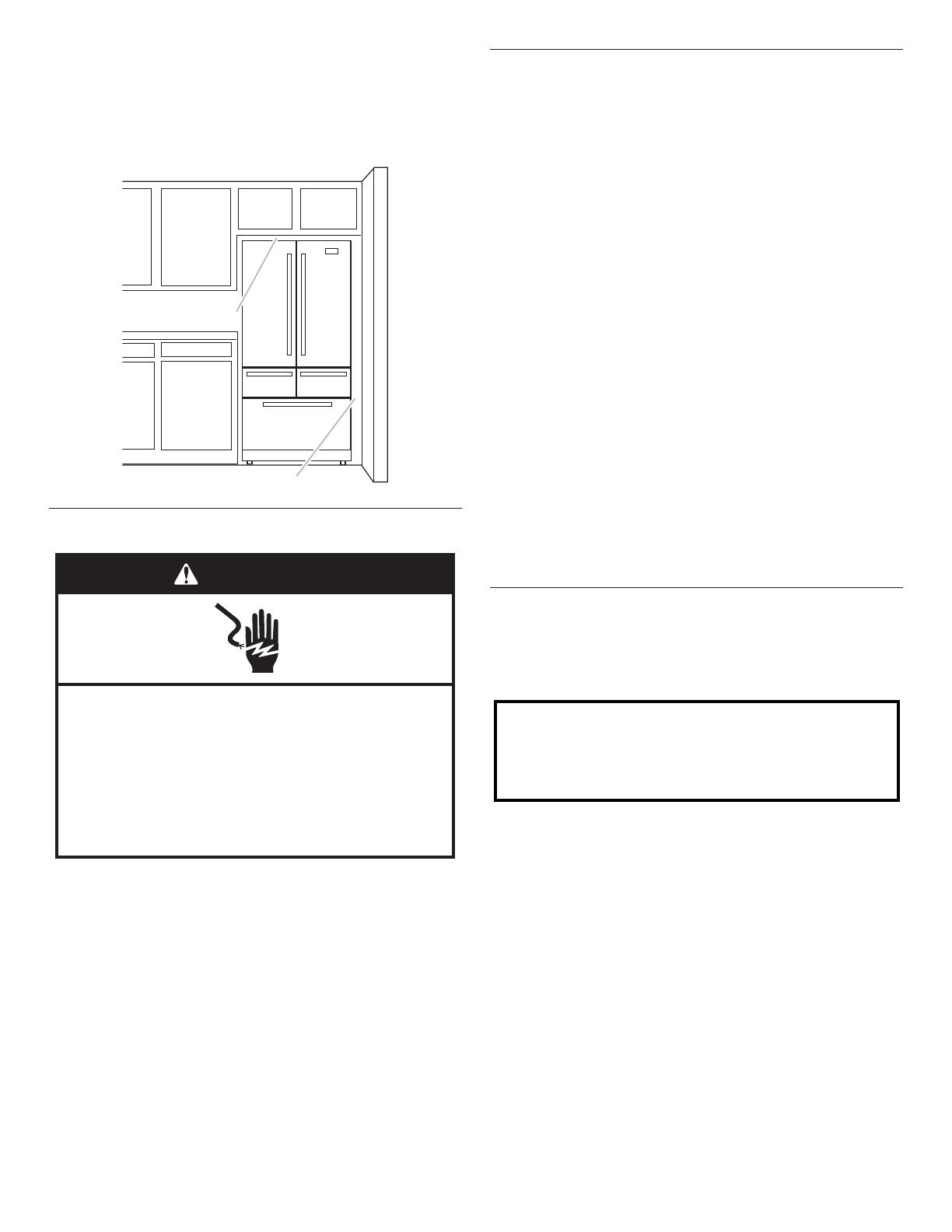
Electrical Shock Hazard
Plug into a grounded 3 prong outlet.
Do not remove ground prong.
Do not use an adapter.
Do not use an extension cord.
Failure to follow these instructions can result in death,
fire, or electrical shock.
WARNING
Do not use with water that is microbiologically unsafe or
of unknown quality without adequate disinfection before
or after the system. Systems certified for cyst reduction
may be used on disinfected waters that may contain
filterable cysts.
1/2" (1.25 cm)
3
3
/4" (9.5 cm)


