
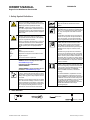
1. Safety Symbol Definitions
DANGER! - Indicates a hazardous situation
which, if not avoided, will result in death or seri-
ous injury. The possible hazards are shown in the
adjoining symbols or explained in the text.
DANGER! - Indique une situation dangereuse
qui, si elle n’est pas évitée, entraînera la mort ou
des blessures graves. Les éventuels risques sont
représentés par les symboles joints ou expliqués
dans le texte.
Indicates a hazardous situation which, if not
avoided, could result in death or serious injury.
The possible hazards are shown in the adjoining
symbols or explained in the text.
Indique une situation dangereuse qui, si elle n’est
pas évitée, entraînera la mort ou des blessures
graves. Les éventuels risques sont représentés
par les symboles joints ou expliqués dans le
texte.
NOTICE –
�
AVIS –
�
Indicates statements not related to personal
injury.
Indicates special instructions.
Signale des consignes non associées aux dom-
mages corporels.
Fournit des instructions spéciales.
CALIFORNIA PROPOSITION 65 WARNINGS
WARNING: Cancer and Reproductive Harm -
www.P65Warnings.ca.gov
PROPOSITION CALIFORNIENNE 65
AVERTISSEMENTS
AVERTISSEMENT : cancer et troubles de la re-
production - www.P65Warnings.ca.gov.
Beware of electric shock from welding electrode
or wiring. Touching the electrode while in contact
with the work or ground can cause electric shock.
Always wear dry gloves. Keep all panels and cov-
ers closed.
Attention au risque d’électrocution due au contact
avec l’électrode de soudage ou les fils. Le fait de
toucher l’électrode tout en étant en contact avec
la pièce ou la terre peut provoquer une électrocu-
tion. Toujours porter des gants secs. Tous les
panneaux et couvercles doivent rester fermés.
Wear safety glasses with side shields.
Porter des lunettes de sécurité avec écrans
latéraux.
Welding sparks can cause fire or explosion. Move
flammables away. Do not weld on closed tanks or
barrels, or on containers that have held combusti-
bles - they can explode. Clean tanks or barrels
properly.
Les étincelles de soudure peuvent provoquer un
incendie ou une explosion. Ne pas souder de cu-
ves ou de tonneaux, au risque qu’ils explosent.
Nettoyer soigneusement les cuves ou tonneaux.
Using a generator indoors CAN KILL YOU IN MI-
NUTES. Generator exhaust contains carbon
monoxide. This is a poison you cannot see or
smell. NEVER use inside a home or garage,
EVEN IF doors and windows are open. Only use
OUTSIDE and far away from windows, doors,
and vents.
L’utilisation d’un groupe autonome à l’intérieur
peut vous tuer en quelques minutes. Les fumées
d’un groupe autonome contient du monoxyde de
carbone. C’est un poison invisible et inodore. JA-
MAIS utiliser dans une maison ou garage, même
avec les portes et fenêtres ouvertes. Uniquement
utiliser à l’EXTERIEUR, loin des portes, fenêtres
et bouches aération.
Have only trained and qualified persons install,
operate, or service this unit. Read the safety infor-
mation at the beginning of these instructions and
in each section. Call your distributor if you do not
understand the directions. For WELDING
SAFETY and EMF information, read owner’s
manual(s).
Ne confiez l’installation, l’exploitation ou l’entre-
tien de cet appareil qu’à des personnes compé-
tentes et qualifiées. Lire les directives de sécurité
au début de ces instructions et dans chaque sec-
tion. Appeler votre distributeur si vous ne compre-
nez pas les directives. Lire le(s) manuel(s)
d’utilisateur pour des renseignements sur la SÉ-
CURITÉ DE SOUDAGE et les champs
électromagnétiques.
2. Tools Needed
OM-222 Page 1
OM-222 Page 1
NGO’s
tools/
helmet weldshield faceshield
glasses hairdryer cclamp rpmmeter benchvise
popriveter
oilcan filtersocket hacksaw belttensiongauge sealant_1
snapringpliers linepliers pencil fusepuller mallet scissors
tape
rubbergloves weldgloves earmuffs electrodewrench
pinextractor2
tip_dress
sealant_2 pump pliers
T_allen
pinextractor (141761)
SOAP
bar soap
Liquid soap
Paper Clip
Needle-Nose Vise Grip
Ground Strap
Thermal Compound
Trowel
Chisel
Torx
ear plugs
OM-222 Page 1
allen_wrench
NGO’s
tools/
flathead philips head wrench
pliers
knife
heavy-duty workclamp light-duty workclamp wirecutter frontcutter
allen_set
needlenose
steelbrush nutdriver
chippinghammer
solderiron
stripcrimp
drill
torque wrench
socket wrench
hammer awl file
crimper
paintbrush
feelergauge flashlight ruler
toothbrush
greasegun
qtip (swab)
vicegrip
handream
punch
filterwrench
strapwrench
airgun
solvent pinextractor eprompuller pipewrench
torque screwdriver
crescent wrench
3/8, 3/4 in.
OM-222 Page 1
allen_wre
nch
NGO’s
tools/
flathead philips h
ead
wrench
pliers
k
nife
heavy-duty workclamp light-duty workclamp wirecutter frontcutter
allen_set
needlenose
s
teelbrush
n
utdriver
chippinghammer
solderiron
stripcrimp
drill
torque wrench
socket wr
ench
hammer awl file
crimper
paintbrush
feelergauge flashlight ruler
toothbrush
greasegun
qtip (swab)
vicegrip
handream
punch
filterwrench
strapwrench
airgun
solvent pinextractor eprompuller pipewrench
torque screwdriver
crescent wrench
3/8, 7/16, 11/16 in.
ORIGINAL INSTRUCTIONS – PRINTED IN USA © Miller Electric Mfg. LLC 2020-02
2020-02 OM-286847A
OWNER’S MANUAL
Engine Drive Weld Remote Panel 301563

OM-286847 Page 2
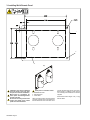
3. Installing Weld Remote Panel
Installation must meet all National
and Local Codes—have only quali-
fied persons make this installation.
Mount panel so connections be-
tween panel and welder/generator
are fully enclosed.
Be sure the mounting structure will
support the weight of the remote
panel and connected cables.
Install panel in orientation shown.
1 Weld Remote Panel
2 Mounting Holes
3 Cutout Area
Select mounting location and mark remote
mounting hole and cutout area placement.
Ensure cables will reach from base unit to
remote. Drill holes and remove cutout area.
Mount panel by installing screws through
four mounting holes. Hardware is customer
supplied.
Weld Remote Panel weighs 3 lb (1.4 kg)
without cables.

OM-286847 Page 3
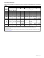
4. Selecting Cable Sizes*
NOTICE – The Total Cable Length in Weld Circuit (see table below) is the combined length of both weld cables. For example, if the power source
is 100 ft (30 m) from the workpiece, the total cable length in the weld circuit is 200 ft (2 cables x 100 ft). Use the 200 ft (60 m) column to determine
cable size.
Weld Cable Size** and Total Cable (Copper) Length in Weld Circuit Not Exceeding***
100 ft (30 m) or Less 150 ft (45 m) 200 ft (60 m) 250 ft (70 m) 300 ft (90 m)
350 ft
(105 m)
400 ft
(120 m)
Welding
Amperes
10 - 60%
Duty Cycle
AWG (mm
2
)
60 - 100%
Duty Cycle
AWG (mm
2
)
10 - 100% Duty Cycle AWG (mm
2
)
100 4 (20) 4 (20) 4 (20) 3 (30) 2 (35) 1 (50) 1/0 (60) 1/0 (60)
150 3 (30) 3 (30) 2 (35) 1 (50) 1/0 (60) 2/0 (70) 3/0 (95) 3/0 (95)
200 3 (30) 2 (35) 1 (50) 1/0 (60) 2/0 (70) 3/0 (95) 4/0 (120) 4/0 (120)
250 2 (35) 1 (50) 1/0 (60) 2/0 (70) 3/0 (95) 4/0 (120) 2x2/0 (2x70) 2x2/0 (2x70)
300 1 (50) 1/0 (60) 2/0 (70) 3/0 (95) 4/0 (120) 2x2/0 (2x70) 2x3/0 (2x95) 2x3/0 (2x95)
350 1/0 (60) 2/0 (70) 3/0 (95) 4/0 (120) 2x2/0 (2x70) 2x3/0 (2x95) 2x3/0 (2x95)
2x4/0
(2x120)
400 1/0 (60) 2/0 (70) 3/0 (95) 4/0 (120) 2x2/0 (2x70) 2x3/0 (2x95)
2x4/0
(2x120)
2x4/0
(2x120)
500 2/0 (70) 3/0 (95) 4/0 (120) 2x2/0 (2x70) 2x3/0 (2x95)
2x4/0
(2x120)
3x3/0 (3x95) 3x3/0 (3x95)
600 3/0 (95) 4/0 (120) 2x2/0 (2x70) 2x3/0 (2x95)
2x4/0
(2x120)
3x3/0 (3x95)
3x4/0
(3x120)
3x4/0
(3x120)
700 4/0 (120) 2x2/0 (2x70) 2x3/0 (2x95)
2x4/0
(2x120)
3x3/0 (3x95)
3x4/0
(3x120)
3x4/0
(3x120)
4x4/0
(4x120)
800 4/0 (120) 2x2/0 (2x70) 2x3/0 (2x95)
2x4/0
(2x120)
3x4/0
(3x120)
3x4/0
(3x120)
4x4/0
(4x120)
4x4/0
(4x120)
* This chart is a general guideline and may not suit all applications. If cable overheats, use next size larger cable.
**Weld cable size (AWG) is based on either a 4 volts or less drop or a current density of at least 300 circular mils per ampere.
( ) = mm
2
for metric use.
***For distances longer than those shown in this guide, see AWS Fact Sheet No. 39, Welding Cables, available from the American Welding
Society at http://www.aws.org.

OM-286847 Page 4
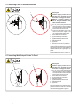
5. Connecting Panel To Welder/Generator
Stop engine.
Failure to properly connect weld ca-
bles may cause excessive heat and
start a fire, or damage your machine.
Maintain a minimum clearance of
0.25 in. (6.35 mm) between uninsu-
lated welding connections and any
other conductive surfaces.
�
Do not place anything between weld
cable terminal and copper bar. Make
sure that the surfaces of the weld cable
terminal and copper bar are clean.
�
If using two weld cables, place one ter-
minal on each side of copper bar. Do
not overlap the weld cable terminals.
1 Correct Weld Cable Connection
2 Incorrect Weld Cable Connection
3 Supplied Weld Output Terminal Screw
4 Supplied Weld Output Terminal Nut
5 Weld Cable Terminal
6 Copper Bar
7 Minimum 0.25 in. (6.35 mm) Clearance
Remove supplied hardware from weld output
terminal. Slide weld cable terminal onto weld
output terminal and secure with hardware so
that weld cable terminal is tight against cop-
per bar.
Recommended torque is 85 in. lb (9.6 N·m).
6. Connecting Weld Output Cables To Panel
Complete Parts List available at www.MillerWelds.com
OM-249336 Page 26
4
2
3
1
5
6
Stop engine.
Failure to properly connect weld ca-
bles may cause excessive heat and
start a fire, or damage your machine.
�
Do not place anything between weld
cable terminal and copper bar. Make
sure that the surfaces of the weld cable
terminal and copper bar are clean.
1 Correct Weld Cable Connection
2 Incorrect Weld Cable Connection
3 Weld Output Terminal
4 Supplied Weld Output Terminal Nut
5 Weld Cable Terminal
6 Copper Bar
Remove supplied nut from weld output termi-
nal. Slide weld cable terminal onto weld out-
put terminal and secure with nut so that weld
cable terminal is tight against copper bar.

OM-286847 Page 5
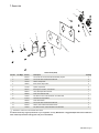
7. Parts List
Remote Panel (Weld)
Item No. Dia. Mkgs. Part No. Description Quantity
1 602154 Screw, 250-20x .50 Hexwhd.50d Stl Pld Slffmg Tap-Rw 4
2 108941 Screw, 250-20x1.00 Hexwhd.61d Gr5 Pld 2
3 180735 Washer, Output Stud 2
4 186621 Boot ,Generic Output Stud 2
5 181169 Spacer, Output Stud 2
6 005107 Bolt, Crg Stl .250-20 X .750 Gr5 Pld 2
7 286631 Label, Nameplate Remote Weld 1
8 286630 Panel, Front Remote Weld 1
9 152461 Nut, 250-20 .44hex .23h Stl Pld Sem Cone Wshr.65d 4
10 241433 Terminal, Pwr Output Black 2
286839 Seal, Weld Remote 1
11 108941 Screw, 250-20x1.00 Hexwhd.61d Gr5 Pld 2
12 602233 Washer, Flat .250idx0.875odx.062t Stl Pld 4
13 152461 Nut, 250-20 .44hex .23h Stl Pld Sem Cone Wshr.65d 2
�
Hardware is common and not available unless listed.
To maintain the factory original performance of your equipment, use only Manufacturer’s Suggested Replacement Parts. Model and
serial number required when ordering parts from your local distributor.
-
 1
1
-
 2
2
-
 3
3
-
 4
4
-
 5
5


Miller REMOTE PANEL WELD Le manuel du propriétaire
- Taper
- Le manuel du propriétaire
- Ce manuel convient également à
dans d''autres langues
Documents connexes
-
Miller GOUGE REMOTE CONTROL 258046 Le manuel du propriétaire
-
-
-
-
-
-
-
-
-