
INSTALLATION INSTRUCTIONS
33-00578EFS-01
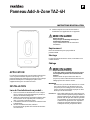
TAZ-4H Add-A-Zone Panel
APPLICATION
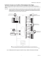
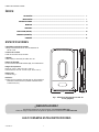
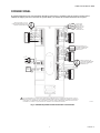
The TAZ-4H is a zone panel used to add zones to the HZ432.
See Fig. 1. The HZ432 provides up to four zones. Each TAZ-
4H can add up to four additional zones for a total of 32 zones.
INSTALLATION
When Installing this Product...
1. Read these instructions carefully. Failure to follow
them could damage the product or cause a hazardous
condition.
2. Check the rating given in the instructions and on the
product to make sure the product is suitable for your
application.
3. Installer must be a trained, experienced service
technician.
4. After installation is complete, check out product
operation as provided in these instructions.
5. Follow local codes for installation and application.
CAUTION
Voltage Hazard.
Can cause electrical shock or equipment damage.
Disconnect power before beginning installation.
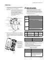
Location
Select a location for the TAZ-4H as close as possible to the
HZ432 panel.
Mounting
The TAZ-4H can mount on a wall, stud, or return duct.
Wiring
CAUTION
Electrical Interference Hazard.
Running cable near line voltage can interfere with
panel operation.
Run cable connecting AZ terminals at least
12 in. from line voltage wiring.
IMPORTANT
Be sure AZ1 and AZ2 wires do not cross and are a
minimum of 12 in. from any line voltage wiring. If not
possible, use shielded cable for AZ1 and AZ2 wires.
NOTE: Only two wires are required to connect the TAZ-4H
panels to the main HZ432 panel. If more than one
TAZ-4H is used, each TAZ-4H can be wired in a
daisy chain or parallel to each other, connecting the
AZ1 and AZ2 terminals between panels. Each AZ1
and AZ2 terminal can fit two wires to simplify daisy
chain wiring.
M38614
TAZ-4H
ZONE A
ZONE B
ZONE C
ZONE D

TAZ-4H ADD-A-ZONE PANEL
33-00578EFS—01 2
TABLE OF CONTENTS
Application ....................................................................................................................... 1
Installation ....................................................................................................................... 1
Specifications ....................................................................................................................... 2
Mounting .......................................................................................................................3
Wiring ....................................................................................................................... 4
Home Mode ....................................................................................................................... 10
Checkout .......................................................................................................................11
Warranty .......................................................................................................................12
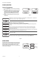
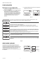
SPECIFICATIONS
Input Ratings:
Voltage: 18-30 VAC 50/60 Hz transformer of 40 VA or more.
Current Draw:
TAZ-4H Zone Panel: 8.5 VA max
Wiring:
18- or 20-gauge solid (not stranded) wire.
Humidity Ratings:
5% to 90% RH non-condensing.
Temperature Ratings:
Shipping: -20° to 150 °F (-29° to 66 °C)
Operating: -40° to 165 °F (-40° to 74 °C)
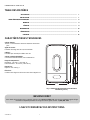
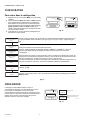
Dimensions:
See Fig. 1.
Emissions:
Complies with FCC Class B, part 15 requirements.
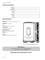
Fig. 1. TAZ-4H Zone Panel Dimensions in in. (mm).
READ AND SAVE THESE INSTRUCTIONS.
M24797A
13-27/62
(341)
1-55/64 (47)
8 (203)
NEED HELP?
For assistance with this product, please visit customer.resideo.com
or call Zoning Hotline toll-free at 1-800-468-1502.

TAZ-4H ADD-A-ZONE PANEL
333-00578EFS—01
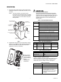
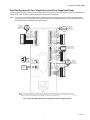
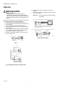
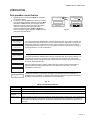
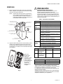
MOUNTING
1. Mount the TAZ-4H Add-A-Zone panel near the HVAC
equipment; locate it on a wall, stud, roof truss, or cold
air return.
NOTE: The TAZ-4H Add-A-Zone panel can be
mounted in any orientation; level it for appear-
ance only. It is best to mount the TAZ-4H Add-
A-Zone panel close to the HZ432 zone panel
when possible.
Fig. 2.
2. Separate the zone panel cover from the base, and use
the base as a template to drill mounting holes. Attach
the base to the wall, stud, roof truss, or duct with
appropriate screws (not included).
Fig. 3.
CAUTION
ELECTRONIC WASTE NOTICE
The product should not be disposed of with other
household waste. Check for the nearest authorized
collection centers or authorized recyclers. The correct
disposal of end of life equipment will help prevent
negative consequences for the environment and
human health.
Table 1. Recommended Thermostats.
Table 2. Recommended Dampers.
Table 3. Maximum Dampers.*
* See SDCR in accessories below if you need to exceed the
number of dampers allowed to a zone.
Maximum dampers per panel is limited by transformer size.
Ensure transformer is large enough to power the panel,
thermostats, wireless adapter module, and dampers.
Table 4. Accessories.
M38631
DATS
(ALTERNATE
LOCATION)
TAZ-4H MOUNTED
ON RETURN DUCT
DATS (AT LEAST 3 FT)
FROM PLENUM
FURNACE OR
AIR HANDLER
SUPPLY DUCT
ZD SERIES
ZONE DAMPERS
CPRD PRESSURE
RELIEF DAMPER
TAZ-4H
MOUNTED
ON WALL
M24807A
Use two screws
for attaching to a
stud or roof truss,
or four screws for
duct or
drywall/plaster
installations.
System Thermostat
Single stage TH1110D2009 (Non-Programmable)
TH4110U2005 (Programmable)
Multistage
conventional TH6220U2000 (Programmable)
TH6220WF2006 (Programmable, Wi-Fi)
Heat pump TH4210U2002 (2H/1C, Programmable)
TH6210U2001 (2H/1C, Programmable)
TH6220U2000 (2H/1C, Programmable)
TH6220WF2006 (2H/1C, Programmable, Wi-Fi)
TH6320WF2003 (3H/2C, Programmable, Wi-Fi)
All the above TH6320WF2003 (Programmable, Wi-Fi)
TH8321WF1001 (Programmable, Wi-Fi)
THX321WFS2001W (Programmable, Wi-Fi)
Type Actuation Round Rectangular
Zone Spring-open/
power-closed ARD (8 VA Max) ZD (8 VA Max)
Zone Power-open/
power-closed RRD
(2.5 VA Max) —
Ambient Temp. Maximum Damper VA per Zone
100 °F (38 °C) 28.8
160 °F (71 °C) 16.8
Accessory Description
40 VA transformer AT140A1042
75 VA transformer AT175A1008
SDCR Secondary Damper Control Relay.
Each SDCR allows you to add
additional dampers to a zone that is
exceeding the maximum from the
chart above.

TAZ-4H ADD-A-ZONE PANEL
33-00578EFS—01 4
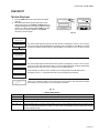
WIRING
CAUTION
Voltage Hazard.
Can cause electrical shock or equipment damage.
Disconnect power before beginning installation.
Wire entire panel before applying transformer power.
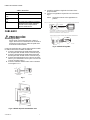
Connect the AZ1 and AZ2 terminals on both panels using
standard 18 gauge thermostat wire:
1. Connect AZ1 on the HZ432 to AZ1 on the TAZ-4H Add-
A-Zone panel. See Fig. 5.
2. Connect AZ2 on the HZ432 to AZ2 on the TAZ-4H Add-
A-Zone panel. See Fig. 5.
3. Connect a 24V, 40 VA transformer to terminals R and C.
R is Hot and C is 24 Vac (Common). See Fig. 4.
4. Connect thermostat wiring as shown in Fig. 7 through
Fig. 11.
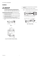
Fig. 4.
Fig. 5. TAZ-4H Add-A-Zone panel wiring.
5. Install dampers using instructions provided with
dampers.
6. Connect dampers to zone panel. See Fig. 6.
NOTE: Multiple dampers can be wired in parallel.
Fig. 6. Damper wiring.
DEDICATED
TRANSFORMER
R
C
M24806A
R
C
POWER
L1
(HOT)
L2
M38619
HZ432
TAZ-4H
ACCESSORIES
AZ1
AZ2
ACCESSORIES
AZ1
AZ2
M38620
RRD OR MARD DAMPER POWER-OPEN POWER-CLOSED
M4 OPEN
M6 CLOSED
ARD OR ZD DAMPER SPRING-OPEN POWER-CLOSED
ZONE B
DAMPER
M4 WIRE IS OPTIONAL ON ARD AND ZD SERIES DAMPERS.
IT IS ONLY USED FOR THE OPEN LIGHT ON THE DAMPER.
M4 OPEN
M6 CLOSED
M1 COMMON
M1
M4
M6
R
ZONE A
DAMPER
M1
M4
M6
M1 COMMON

TAZ-4H ADD-A-ZONE PANEL
533-00578EFS—01
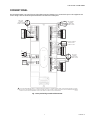
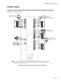
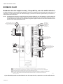
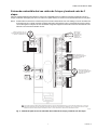
CONVENTIONAL
The following diagram is an overall view of wiring thermostats and dampers for a conventional system. The equipment and
sensor wiring is done at the HZ432 panel and shown in the literature for that panel.
Fig. 7. Zone panel wiring conventional thermostats.
TAZ-4H
ZONE A
ZONE B
ZONE C
ZONE D
HOME
CONFIG
CHECK OUT
ADJUST SETTING
M1
M4
M6
R
C
W1/E
W2
W3
Y1
Y2
G
O/B
L
M1
M4
M6
R
C
W1/E
W2
W3
Y1
Y2
G
O/B
L
M1
M4
M6
R
C
W1/E
W2
W3
Y1
Y2
G
O/B
L
M4 OPEN
M6 CLOSED
M1 COMMON
M38621
ARD OR ZD DAMPER
SPRING-OPEN
POWER-CLOSED
DEDICATED
TRANSFORMER
R
C
L1
(HOT)
L2
ARD OR ZD
DAMPER
SPRING-OPEN
POWER-CLOSED
ARD OR ZD
DAMPER
SPRING-OPEN
POWER-CLOSED
M1
M4
M6
R
C
W1/E
W2
W3
Y1
Y2
G
O/B
L
ZONE D
DAMPER
THERMOSTAT
POWERACCESSORIES
ZONE B
DAMPER
THERMOSTATZONE A
DAMPER
THERMOSTAT ZONE C
DAMPER
THERMOSTAT
R
C
TO AZ1
AND AZ2
ON HZ432
AZ1
AZ2
Rc
R
C
W
W2
Y
Y2
G
Rc
R
C
W
W2
Y
Y2
G
Rc
R
C
W
W2
Y
Y2
G
Rc
R
C
W
W2
Y
Y2
G
RRD OR MARD
DAMPER
POWER-OPEN
POWER-CLOSED
1
1
ONLY TWO WIRES ARE REQUIRED TO CONNECT THE TAZ-4H PANELS TO THE MAIN HZ432 PANEL. IF MORE THAN ONE TAZ-4H IS USED,
EACH TAZ-4H CAN BE WIRED IN A DAISY CHAIN OR PARALLEL TO EACH OTHER, CONNECTING THE AZ1 AND AZ2 TERMINALS BETWEEN
PANELS. EACH AZ1 AND AZ2 TERMINAL CAN FIT TWO WIRES TO SIMPLIFY DAISY CHAIN WIRING.

TAZ-4H ADD-A-ZONE PANEL
33-00578EFS—01 6
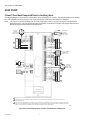
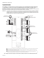
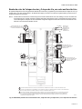
HEAT PUMP
2 Heat/1 Cool Heat Pump with Electric Auxiliary Heat
The following diagram is an overall view of wiring thermostats and dampers for a 2 heat/1 cool heat pump with electric auxiliary
heat. The equipment and sensor wiring is done at the HZ432 panel and shown in the literature for that panel.
NOTE: You can use a conventional thermostat for a heat pump system; however, em heat can only be controlled by heat
pump thermostats or by pressing the Emergency Heat button on the HZ432 zone panel. The diagram below shows a
heat pump thermostat used with a heat pump system.
Fig. 8. Zone panel wiring heat pump, 2 heat/1 cool with electric auxiliary heat.
3
1
2
JUMP W1/E TO W2 AT THE THERMOSTAT CONNECTIONS ON ALL ZONES OF THE ZONE PANEL.
FOR THERMOSTATS WITH SEPARATE O AND B TERMINALS, ATTACH O FOR COOL CHANGEOVER VALVES OR ATTACH B FOR HEAT
CHANGEOVER VALVES.
ONLY TWO WIRES ARE REQUIRED TO CONNECT THE TAZ-4H PANELS TO THE MAIN HZ432 PANEL. IF MORE THAN ONE TAZ-4H IS USED,
EACH TAZ-4H CAN BE WIRED IN A DAISY CHAIN OR PARALLEL TO EACH OTHER, CONNECTING THE AZ1 AND AZ2 TERMINALS BETWEEN
PANELS. EACH AZ1 AND AZ2 TERMINAL CAN FIT TWO WIRES TO SIMPLIFY DAISY CHAIN WIRING.
1
2
1
2
1
2
1
2
TAZ-4H
ZONE A
ZONE B
ZONE C
ZONE D
M1
M4
M6
R
C
W1/E
W2
W3
Y1
Y2
G
O/B
L
M1
M4
M6
R
C
W1/E
W2
W3
Y1
Y2
G
O/B
L
HOME
CONFIG
CHECK OUT
ADJUST SETTING
M4 OPEN
M6 CLOSED
M1 COMMON
M38622
ARD OR ZD DAMPER
SPRING-OPEN
POWER-CLOSED
DEDICATED
TRANSFORMER
R
C
L1
(HOT)
L2
ARD OR ZD
DAMPER
SPRING-OPEN
POWER-CLOSED
ARD OR ZD
DAMPER
SPRING-OPEN
POWER-CLOSED
ZONE D
DAMPER
THERMOSTAT
POWER
ZONE B
DAMPER
THERMOSTATZONE A
DAMPER
THERMOSTAT ZONE C
DAMPER
THERMOSTAT
R
C
TO AZ1
AND AZ2
ON HZ432
AZ1
AZ2
Rc
R
C
AUX/E
Y
G
O/B
Rc
R
C
AUX/E
Y
G
O/B
Rc
R
C
AUX/E
Y
G
O/B
Rc
R
C
AUX/E
Y
G
O/B
RRD OR MARD
DAMPER
POWER-OPEN
POWER-CLOSED
3
M1
M4
M6
R
C
W1/E
W2
W3
Y1
Y2
G
O/B
L
ACCESSORIES
M1
M4
M6
R
C
W1/E
W2
W3
Y1
Y2
G
O/B
L

TAZ-4H ADD-A-ZONE PANEL
733-00578EFS—01
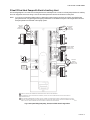
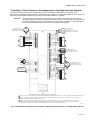
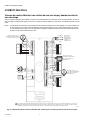
3 Heat/2 Cool Heat Pump with Electric Auxiliary Heat
The following diagram is an overall view of wiring thermostats and dampers for a 3 heat/2 cool heat pump with electric auxiliary
heat. The equipment and sensor wiring is done at the HZ432 panel and shown in the literature for that panel.
NOTE: You can use a conventional thermostat for a heat pump system; however, em heat can only be controlled by heat
pump thermostats or by pressing the Emergency Heat button on the HZ432 zone panel. The diagram below shows a
heat pump thermostat used with a heat pump system.
Fig. 9. Zone panel wiring heat pump, 3 heat/2 cool with electric stage 3 heat.
3
1
2
JUMP W1/E TO W3 AT THE THERMOSTAT CONNECTIONS ON ALL ZONES OF THE ZONE PANEL.
FOR THERMOSTATS WITH SEPARATE O AND B TERMINALS, ATTACH O FOR COOL CHANGEOVER VALVES OR ATTACH B FOR HEAT
CHANGEOVER VALVES.
ONLY TWO WIRES ARE REQUIRED TO CONNECT THE TAZ-4H PANELS TO THE MAIN HZ432 PANEL. IF MORE THAN ONE TAZ-4H IS USED,
EACH TAZ-4H CAN BE WIRED IN A DAISY CHAIN OR PARALLEL TO EACH OTHER, CONNECTING THE AZ1 AND AZ2 TERMINALS BETWEEN
PANELS. EACH AZ1 AND AZ2 TERMINAL CAN FIT TWO WIRES TO SIMPLIFY DAISY CHAIN WIRING.
1
2
1
2
1
2
1
2
HOME
CONFIG
CHECK OUT
ADJUST SETTING
TAZ-4H
ZONE A
ZONE B
ZONE C
ZONE D
M1
M4
M6
R
C
W1/E
W2
W3
Y1
Y2
G
O/B
L
M1
M4
M6
R
C
W1/E
W2
W3
Y1
Y2
G
O/B
L
M4 OPEN
M6 CLOSED
M1 COMMON
M38623
ARD OR ZD DAMPER
SPRING-OPEN
POWER-CLOSED
DEDICATED
TRANSFORMER
R
C
L1
(HOT)
L2
ARD OR ZD
DAMPER
SPRING-OPEN
POWER-CLOSED
ARD OR ZD
DAMPER
SPRING-OPEN
POWER-CLOSED
ZONE D
DAMPER
THERMOSTAT
POWER
ZONE B
DAMPER
THERMOSTATZONE A
DAMPER
THERMOSTAT ZONE C
DAMPER
THERMOSTAT
R
C
TO AZ1
AND AZ2
ON HZ432
AZ1
AZ2
Rc
R
C
AUX/E
Y
Y2
G
O/B
Rc
R
C
AUX/E
Y
Y2
G
O/B
Rc
R
C
AUX/E
Y
Y2
G
O/B
Rc
R
C
AUX/E
Y
G
O/B
RRD OR MARD
DAMPER
POWER-OPEN
POWER-CLOSED
3
M1
M4
M6
R
C
W1/E
W2
W3
Y1
Y2
G
O/B
L
ACCESSORIES
M1
M4
M6
R
C
W1/E
W2
W3
Y1
Y2
G
O/B
L

TAZ-4H ADD-A-ZONE PANEL
33-00578EFS—01 8
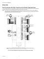
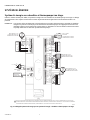
DUAL FUEL
Dual Fuel System with Single-Stage Furnace and Single-Stage Heat Pump
Use the following diagram for wiring a dual fuel system with single-stage furnace and single-stage heat pump. The equipment
and sensor wiring is done at the HZ432 panel and shown in the literature for that panel.
NOTE: You can use a conventional thermostat for a heat pump system; however, em heat can only be controlled by heat
pump thermostats or by pressing the Emergency Heat button on the HZ432 zone panel. The diagram below shows a
heat pump thermostat used with a heat pump system.
Fig. 10. Zone panel wiring dual fuel: single-stage furnace and single-stage heat pump.
1ONLY TWO WIRES ARE REQUIRED TO CONNECT THE TAZ-4H PANELS TO THE MAIN HZ432 PANEL. IF MORE THAN ONE TAZ-4H IS USED,
EACH TAZ-4H CAN BE WIRED IN A DAISY CHAIN OR PARALLEL TO EACH OTHER, CONNECTING THE AZ1 AND AZ2 TERMINALS BETWEEN
PANELS. EACH AZ1 AND AZ2 TERMINAL CAN FIT TWO WIRES TO SIMPLIFY DAISY CHAIN WIRING.
HOME
CONFIG
CHECK OUT
ADJUST SETTING
TAZ-4H
ZONE A
ZONE B
ZONE C
ZONE D
M1
M4
M6
R
C
W1/E
W2
W3
Y1
Y2
G
O/B
L
M1
M4
M6
R
C
W1/E
W2
W3
Y1
Y2
G
O/B
L
M4 OPEN
M6 CLOSED
M1 COMMON
M38624
ARD OR ZD DAMPER
SPRING-OPEN
POWER-CLOSED
DEDICATED
TRANSFORMER
R
C
L1
(HOT)
L2
ARD OR ZD
DAMPER
SPRING-OPEN
POWER-CLOSED
ARD OR ZD
DAMPER
SPRING-OPEN
POWER-CLOSED
ZONE D
DAMPER
THERMOSTAT
POWER
ZONE B
DAMPER
THERMOSTATZONE A
DAMPER
THERMOSTAT ZONE C
DAMPER
THERMOSTAT
R
C
TO AZ1
AND AZ2
ON HZ432
AZ1
AZ2
Rc
R
C
AUX/E
Y
Y2
G
O/B
Rc
R
C
AUX/E
Y
Y2
G
O/B
Rc
R
C
AUX/E
Y
Y2
G
O/B
Rc
R
C
AUX/E
Y
Y2
G
O/B
RRD OR MARD
DAMPER
POWER-OPEN
POWER-CLOSED
1
M1
M4
M6
R
C
W1/E
W2
W3
Y1
Y2
G
O/B
L
ACCESSORIES
M1
M4
M6
R
C
W1/E
W2
W3
Y1
Y2
G
O/B
L

TAZ-4H ADD-A-ZONE PANEL
933-00578EFS—01
Dual Fuel System with Two-Stage Furnace and Two-Stage Heat Pump
Use the following diagram for wiring a dual fuel system with two-stage furnace and two-stage heat pump. The equipment and
sensor wiring is done at the HZ432 panel and shown in the literature for that panel.
NOTE: You can use a conventional thermostat for a heat pump system; however, em heat can only be controlled by heat
pump thermostats or by pressing the Emergency Heat button on the HZ432 zone panel. The diagram below shows a
heat pump thermostat used with a heat pump system.
Fig. 11. Zone panel wiring dual fuel: two-stage furnace and two-stage heat pump.
1ONLY TWO WIRES ARE REQUIRED TO CONNECT THE TAZ-4H PANELS TO THE MAIN HZ432 PANEL. IF MORE THAN ONE TAZ-4H IS USED,
EACH TAZ-4H CAN BE WIRED IN A DAISY CHAIN OR PARALLEL TO EACH OTHER, CONNECTING THE AZ1 AND AZ2 TERMINALS BETWEEN
PANELS. EACH AZ1 AND AZ2 TERMINAL CAN FIT TWO WIRES TO SIMPLIFY DAISY CHAIN WIRING.
HOME
CONFIG
CHECK OUT
ADJUST SETTING
TAZ-4H
ZONE A
ZONE B
ZONE C
ZONE D
M1
M4
M6
R
C
W1/E
W2
W3
Y1
Y2
G
O/B
L
M1
M4
M6
R
C
W1/E
W2
W3
Y1
Y2
G
O/B
L
M4 OPEN
M6 CLOSED
M1 COMMON
M38625
ARD OR ZD DAMPER
SPRING-OPEN
POWER-CLOSED
DEDICATED
TRANSFORMER
R
C
L1
(HOT)
L2
ARD OR ZD
DAMPER
SPRING-OPEN
POWER-CLOSED
ARD OR ZD
DAMPER
SPRING-OPEN
POWER-CLOSED
ZONE D
DAMPER
THERMOSTAT
POWER
ZONE B
DAMPER
THERMOSTATZONE A
DAMPER
THERMOSTAT ZONE C
DAMPER
THERMOSTAT
R
C
TO AZ1
AND AZ2
ON HZ432
AZ1
AZ2
Rc
R
C
AUX/E
Y
Y2
G
O/B
Rc
R
C
AUX/E
Y
Y2
G
O/B
Rc
R
C
AUX/E
Y
Y2
G
O/B
Rc
R
C
AUX/E
Y
Y2
G
O/B
RRD OR MARD
DAMPER
POWER-OPEN
POWER-CLOSED
1
M1
M4
M6
R
C
W1/E
W2
W3
Y1
Y2
G
O/B
L
ACCESSORIES
M1
M4
M6
R
C
W1/E
W2
W3
Y1
Y2
G
O/B
L

TAZ-4H ADD-A-ZONE PANEL
33-00578EFS—01 10
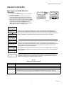
CONFIGURATION
To Enter Configuration
1. Press the Mode button once (the Config LED will light
up).
2. Use the Back and Next buttons to navigate through the
configuration settings. Scroll through the selection
choices by using the “Adjust Setting” Left and Right
arrow buttons. Pressing Next enters the selected
option for that menu item and advances to the next
menu.
3. The flow chart below illustrates TAZ-4H zone panel
configuration. Fig. 12.
Fig. 13.
HOME MODE
The display at home mode will either indicate communication
is good or at least one zone is failing to communicate to the
HZ432 zone panel. The TAZ-4H panel is factory configured
for zones 5-8 with conventional thermostats, so it will
indicate communication status as soon as it is powered even
if it has not been configured.
Fig. 14.
HOME
MODE
BACK NEXT
CONFIG
CHECK OUT
ADJUST SETTING
HOME
MODE
BACK NEXT
CONFIG
CHECK OUT
ADJUST SETTING
M38626
Which Zones is this TAZ-4H controlling? Since the HZ432 is controlling zones 1-4, options are:
[5-8], [9-12], [13-16], [17-20], [21-24], [25-28], [29-32]
What type of thermostat is controlling each zone?
Options are: [CONV], [HTPUMP-O], [HTPUMP-B], [NOT CONNCTD].
“HTPUMP-O” would be a heat pump thermostat configured to energize the reversing valve in
cooling.
There is a letter after the zone number because the lights, and thermostat/damper wiring
connections are labeled Zone A-D. This is because a TAZ-4H panel could be configured to
control zones 5-8, 6-9, etc.
When you are in checkout, the first zone that the panel controls will have an A. This could be 5A,
9A, 13A, depending on how many TAZ-4H panels are used.
Options are: [1]-[10]
Make sure you select “YES” using the arrow button before pressing the NEXT button.
M38627
ZONES CONTROLLED
[5-8] ->
ZONE 5-A TSTAT
[CONV] ->
ZONE 6-B TSTAT
[CONV] ->
ZONE 7-C TSTAT
[CONV] ->
ZONE 8-D TSTAT
[CONV] ->
LCD CONTRAST
<- [5] ->
SAVE CHANGES?
[NO] YES
HOME
MODE
BACK NEXT
CONFIG
CHECK OUT
ADJUST SETTING
ZONES 5-8
COMM OK
COMMUNICATION
OK
ZONES 5-8
COMM ERROR
COMMUNICATION
ISSUE FROM
TAZ-4H TO HZ432
ZONES 5-8
COMM OK
M38628

TAZ-4H ADD-A-ZONE PANEL
11 33-00578EFS—01
CHECKOUT
To Enter Checkout
1. Press the Mode button twice (the Checkout LED will
light up).
2. The Chart below shows the Checkout options and
information shown. Use the Back and Next buttons to
navigate through the checkout options. When testing a
damper use “Adjust Setting” Left and Right arrow but-
tons to open or close the damper. Pressing Next
advances to the next menu. Fig. 15.
Fig. 16.
Table 5. LED Operation.
HOME
MODE
BACK NEXT
CONFIG
CHECK OUT
ADJUST SETTING
HOME
MODE
BACK NEXT
CONFIG
CHECK OUT
ADJUST SETTING
M38629
LED Description
Home Zone Panel is in Home mode.
Config Zone panel is in Configuration mode.
Checkout Zone panel is in Checkout mode.
Zone A, B, C, D Solid green when open or opening. Solid red when closed or closing. Blinking amber when the VA draw of the
dampers exceeds the specified VA, or if there is a short circuit on the damper or thermostat wiring, causing
that zone's breaker to trip.
The zones shown depend on which zones the TAZ-4H is configured to control. If set to control
zones 9-12 it will start with damper 9A. The lights on the zone panel are A-D. When a zone light
is green, that damper should be open or opening. When a zone light is red, it is closed or closing.
The zones shown depend on which zones the TAZ-4H is configured to control. If set to control
zones 9-12 it will start with Zone 9A STAT. You can see which terminals are being energized by
the thermostat at each zone. This is a useful tool for troubleshooting.
In the examples on the left, zone 5-A thermostat is energizing W1, Zone 6B thermostat is
energizing G, Zone 7-C, and 8-D thermostats are not energizing any terminals.
There is not a checkout setting to turn on the heat cool or fan on the TAZ-4H panel. The HZ432
has settings to turn on the heat, cool, or fan stages in checkout.
M38630
TEST DAMPER 5-A
[OPEN] CLOSED
TEST DAMPER 6-B
[OPEN] CLOSED
TEST DAMPER 7-C
[OPEN] CLOSED
TEST DAMPER 8-D
[OPEN] CLOSED
TSTAT 5-A INPUTS
W1----- ----------
TSTAT 6-B INPUTS
G----- ----------
TSTAT 7-C INPUTS
------- ----------
STAT 8-D INPUTS
------- ----------
TEST HEATING, COOLING
OR FAN?

TAZ-4H ADD-A-ZONE PANEL
© 2021 Resideo Technologies, Inc. All rights reserved.
This product is manufactured by Resideo Technologies, Inc. and its affiliates.
Tous droits réservés. Ce produit est fabriqué par Resideo Technologies, Inc. et ses sociétés affiliées.
Todos los derechos reservados. Este producto es fabricado por Resideo Technologies, Inc. y sus afiliados.
www.resideo.com
Resideo Technologies, Inc.
1985 Douglas Drive North, Golden Valley, MN 55422
1-800-468-1502
33-00578EFS—01 M.S. 05-21 | Printed in United States
Table 6. Troubleshooting.
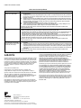
WARRANTY
Resideo warrants this product to be free from defects in
workmanship or materials, under normal use and service, for a period
of five (5) years from the date of first purchase by the original
purchaser. If at any time during the warranty period the product is
determined to be defective due to workmanship or materials,
Resideo shall repair or replace it (at Resideo's option).
If the product is defective,
(i) return it, with a bill of sale or other dated proof of purchase, to the
place from which you purchased it; or
(ii) call Resideo Customer Care at 1-800-468-1502. Customer Care
will make the determination whether the product should be returned
to the following address: Resideo Return Goods, 1985 Douglas Dr. N.,
Golden Valley, MN 55422, or whether a replacement product can be
sent to you.
This warranty does not cover removal or reinstallation costs. This
warranty shall not apply if it is shown by Resideo that the defect was
caused by damage which occurred while the product was in the
possession of a consumer.
Resideo's sole responsibility shall be to repair or replace the product
within the terms stated above. RESIDEO SHALL NOT BE LIABLE FOR
ANY LOSS OR DAMAGE OF ANY KIND, INCLUDING ANY INCIDENTAL
OR CONSEQUENTIAL DAMAGES RESULTING, DIRECTLY OR
INDIRECTLY, FROM ANY BREACH OF ANY WARRANTY, EXPRESS OR
IMPLIED, OR ANY OTHER FAILURE OF THIS PRODUCT.
Some states do not allow the exclusion or limitation of incidental or
consequential damages, so this limitation may not apply to you.
THIS WARRANTY IS THE ONLY EXPRESS WARRANTY RESIDEO
MAKES ON THIS PRODUCT. THE DURATION OF ANY IMPLIED
WARRANTIES, INCLUDING THE WARRANTIES OF MERCHANTABILITY
AND FITNESS FOR A PARTICULAR PURPOSE, IS HEREBY LIMITED TO
THE FIVE YEAR DURATION OF THIS WARRANTY. Some states do not
allow limitations on how long an implied warranty lasts, so the above
limitation may not apply to you.
This warranty gives you specific legal rights, and you may have other
rights which vary from state to state. If you have any questions
concerning this warranty, please write Resideo Customer Care, 1985
Douglas Dr, Golden Valley, MN 55422 or call 1-800-468-1502.
Problem Description
TAZ-4H does not communicate to
HZ432 1. Verify HZ432 is configured for 4 zones + ADDZONE in the configuration settings.
2. Verify the TAZ-4H is configured for the correct zones. If two TAZ-4H panels are used, we would expect one of the pan-
els to be configured as zones 5-8 and the other to be configured as zones 9-12. See the configuration section in this
guide.
3. Verify the wiring connections on AZ1 and AZ2 are good. AZ1 from TAZ-4H should be matched to AZ1 on HZ432 and
AZ2 from TAZ-4H should be matched to AZ2 on HZ432. You can fit two wires per terminal if multiple TAZ-4H panels
are used and these can be wired in parallel or daisy chained.
4. Verify the transformers powering the HZ432 and TAZ-4 are in phase.
5. What is the DC voltage at AZ1 and AZ2? (It should be about 12.) If it is below 9 VDC, remove the wires at the HZ432
and measure the voltage at those terminals on the HZ432.
For further troubleshooting, call the zoning hotline at 800-468-1502.
Damper is in wrong position •When the HZ432 is in idle mode (no call for heat, cool, or fan and not in purge), we would expect all dampers on the TAZ-
4H to be open and all the zone lights to be green.
•If the HZ432 indicates a call for cool, all zones on the TAZ-4H calling for cool at that time should have a green zone LED
and have approx. 24 volts AC from M1 to M4 (open). All zones not calling for cool at that time should have a red zone LED
and have approx. 24 volts AC from M1 to M6 (closed).
•If the HZ432 indicates a call for heat, all zones on the TAZ-4H calling for heat at that time should have a green zone LED
and have approx. 24 volts AC from M1 to M4 (open). All zones not calling for heat at that time should have a red zone LED
and have approx. 24 volts AC from M1 to M6 (closed).
For further troubleshooting, call the zoning hotline at 800-468-1502.
When one of the zones on the TAZ-
4H calls for heat or cool, the HZ432
stays in idle (no heat, cool, or purge
light lit).
1. Verify the settings and wiring are correct as described in “TAZ-4 does not communicate to HZ432” above.
2. Go into Checkout mode and see what the TAZ-4 shows for the inputs from the thermostat on that zone. Verify the ter-
minals energized are as expected. For example, if zone 5-A shows inputs on W1 and Y1, and that zone is configured
for a conventional thermostat, there is a problem. A conventional thermostat should not energize W1 and Y1 at the
same time. This could be caused by a shorted wire, a miswired thermostat, or a misconfigured thermostat.
For further troubleshooting, call the zoning hotline at 800-468-1502.

INSTRUCTIONS D'INSTALLATION
Panneau Add-A-ZoneTAZ-4H
APPLICATION
LeTAZ-4H est un panneau de zone qui permet d'ajouter des
zones au panneauHZ432. Reportez-vous à la Fig. 1. Le
panneauHZ432 peut alimenter jusqu'à quatre zones. Chaque
panneauTAZ-4H peut accueillir jusqu'à quatre zones
supplémentaires, pour un total de 32zones.
INSTALLATION
Lors de l'installation de ce produit...
1. Lisez ces instructions attentivement. Le non-respect
de ces consignes risque d'endommager le produit ou
de créer une situation dangereuse.
2. Vérifier les caractéristiques nominales indiquées dans
les instructions et sur le produit pour s'assurer que
celui-ci convient à l'utilisation prévue.
3. L'installateur doit être un technicien en entretien formé
et expérimenté.
4. Une fois l'installation terminée, vérifier le
fonctionnement du produit de la manière décrite dans
ces instructions.
5. Veuillez respecter les codes locaux relatifs à
l'installation et à l'application de ces appareils.
MISE EN GARDE
Risque de tension.
Peut provoquer une décharge électrique ou
endommager l'équipement.
Coupez l'alimentation avant de commencer
l'installation.
Emplacement
Placez leTAZ-4H aussi près que possible du
panneauHZ432.
Montage
LeTAZ-4H peut être monté sur un mur, un montant ou un
conduit de retour.
Câblage
MISE EN GARDE
Risque d'interférence électrique.
La pose d'un câble à proximité de la tension secteur
est susceptible de perturber le fonctionnement du
panneau.
Veillez à laisser un espace d'au moins 30,5cm
(12pouces) entre le câble reliant les bornes AZ et le
câblage porteur de la tension secteur.
IMPORTANT
Assurez-vous que les filsAZ1 etAZ2 ne se croisent
pas et qu'ils passent à un minimum de 30,5cm
(12pouces) de tout câblage porteur de la tension
secteur. Si cela est impossible, employez un câble
blindé pour les filsAZ1 etAZ2.
REMARQUE : Deux câbles suffisent pour connecter les pan-
neauxTAZ-4H au panneau principalHZ432. Si
plus d'un panneauTAZ-4H est utilisé, chaque
panneauTAZ-4H peut être câblé en guirlande
ou en parallèle, en connectant les bornesAZ1
etAZ2 entre les panneaux. Pour simplifier le
montage en guirlande, chaque borneAZ1
etAZ2 peut recevoir jusqu'à deux câbles.
M38614
TAZ-4H
ZONE A
ZONE B
ZONE C
ZONE D

PANNEAU ADD-A-ZONETAZ-4H
33-00578EFS—01 2
TABLE DES MATIÈRES
APPLICATION ....................................................................................................................... 1
INSTALLATION ....................................................................................................................... 1
CARACTÉRISTIQUES TECHNIQUES ....................................................................................................................... 2
MONTAGE ....................................................................................................................... 3
CÂBLAGE ....................................................................................................................... 4
MODE MAISON ....................................................................................................................... 10
VÉRIFICATION ....................................................................................................................... 11
GARANTIE .......................................................................................................................12
CARACTÉRISTIQUES TECHNIQUES
Valeurs d'entrée:
Tension: Transformateur18-30Vca 50/60Hz de 40VA ou
plus.
Appel de courant:
Panneau de zonageTAZ-4H: 8,5VA maximum.
Câblage:
Fil massif (non torsadé) de calibre18 ou20.
Valeurs nominales d'humidité:
5% à 90% d'humidité relative, sans condensation.
Plages de températures:
Expédition: -20 à 66°C (-29 à 150°F)
Fonctionnement: -40 à 74°C (-40 à 165°F)
Dimensions:
Reportez-vous à la Fig. 1.
Émissions:
Conforme aux exigences de la norme FCC ClasseB, partie15.
Fig. 1. Dimensions du panneau de zoneTAZ-4H en
millimètres (pouces).
LISEZ ET CONSERVEZ CES INSTRUCTIONS.
MF24797A
341
(13-27/62)
47 (1-55/64)
203 (8)
BESOIN D'AIDE?
Pour obtenir de l'assistance avec ce produit, visitez le site customer.resideo.com. Vous pouvez également appeler la ligne
d'assistance téléphonique dédiée au zonage au numéro gratuit suivant: 1(800) 468-1502.

PANNEAU ADD-A-ZONETAZ-4H
333-00578EFS—01
MONTAGE
1. Montez le panneauTAZ-4H Add-A-Zone à proximité de
l'équipement CVC; placez-le sur un mur, un montant,
une ferme de toit ou un retour d'air froid.
REMARQUE : Le panneauTAZ-4H Add-A-Zone peut
être monté dans n'importe quelle orien-
tation; ne le mettez à niveau que pour
des raisons esthétiques. Dans la
mesure du possible, il est préférable de
monter le panneauTAZ-4H Add-A-Zone
à proximité du panneau de
zonageHZ432.
Fig. 2.
2. Séparez le couvercle du panneau de zone de sa base, et
utilisez la base comme modèle pour percer les trous de
montage. Fixez la base au mur, au montant, à la ferme
de toit ou au conduit au moyen de vis appropriées (non
incluses).
Fig. 3.
MISE EN GARDE
AVIS DE DÉCHET ÉLECTRONIQUE
Le produit ne devrait pas être jeté avec d'autres
ordures ménagères. Adressez-vous au centre de
collecte ou de récupération autorisé le plus proche.
La mise au rebut appropriée de l'équipement en fin de
vie permettra d'éviter les conséquences négatives sur
l'environnement et la santé.
Tableau 1. Thermostats recommandés.
Tableau 2. Registres recommandés.
Tableau 3. Nombre maximal de registres*.
* Si vous avez besoin de dépasser le nombre de registres
autorisés pour une zone donnée, consultez leSDCR dans la
section des accessoires ci-dessous.
Le nombre maximum de registres par panneau est limité
par la taille du transformateur.
Assurez-vous que le transformateur est suffisamment
puissant pour alimenter le panneau, les thermostats, le
module adaptateur sans fil et les registres.
Tableau 4. Accessoires.
MF38631
DATS (AUTRE
EMPLACEMENT)
CONDUIT DE RETOUR
MONTÉTAZ-4H
DATS (AU MOINS 3PO)
DU PLÉNUM
CHAUDIÈRE OU APPAREIL
DE TRAITEMENT DE L'AIR
CONDUIT
D'ALIMENTATION
REGISTRES DE ZONAGE
DE LA SÉRIE ZD
REGISTRE DE
SURPRESSION CPRD
TAZ-4H MONTÉ
SUR LE MUR
M24807A
Utilisez deux vis
pour la fixation à
un montant ou à
une ferme de toit,
ou quatre vis pour
les installations
sur un conduit,
une cloison sèche
ou du plâtre.
Système Thermostat
Une phase TH1110D2009 (Non programmable)
TH4110U2005 (Programmable)
Multiphases
classique TH6220U2000 (Programmable)
TH6220WF2006 (Programmable, Wi-Fi)
Thermo-
pompe TH4210U2002 (2H/1C, Programmable)
TH6210U2001 (2H/1C, Programmable)
TH6220U2000 (2H/1C, Programmable)
TH6220WF2006 (2H/1C, Programmable, Wi-Fi)
TH6320WF2003 (3H/2C, Programmable, Wi-Fi)
Toutes ces
réponses TH6320WF2003 (Programmable, Wi-Fi)
TH8321WF1001 (Programmable, Wi-Fi)
THX321WFS2001W (Programmable, Wi-Fi)
Type Actionnement Rond Rectangulaire
Zone Ouverture à ressort,
fermeture motorisée ARD (8 VA
maximum) ZD (8 VA
maximum)
Zone Ouverture motorisée,
fermeture motorisée RRD (2,5VA
maximum) —
Température ambiante VA maximale de registre par zone
100 °F (38 °C) 28,8
160 °F (71 °C) 16,8
Accessoire Description
Transformateur 40VA AT140A1042
Transformateur 75VA AT175A1008
SDCR Relais de contrôle du registre secondaire.
Chaque SDCR vous permet d'ajouter des
registres supplémentaires à une zone qui
dépasse le maximum indiqué dans le
tableau ci-dessus.

PANNEAU ADD-A-ZONETAZ-4H
33-00578EFS—01 4
CÂBLAGE
MISE EN GARDE
Risque de tension.
Peut provoquer une décharge électrique ou
endommager l'équipement. Coupez l'alimentation
avant de commencer l'installation. Câblez l'ensemble
du panneau avant de mettre le transformateur sous
tension.
Connectez les bornesAZ1 etAZ2 des deux panneaux à l'aide
d'un câble de thermostat standard de calibre18:
1. Connectez la borneAZ1 du panneauHZ432 à la
borneAZ1 du panneauTAZ-4H Add-A-Zone. Reportez-
vous à la Fig. 5.
2. Connectez la borneAZ2 du panneauHZ432 à la
borneAZ2 du panneauTAZ-4H Add-A-Zone. Reportez-
vous à la Fig. 5.
3. Connectez un transformateur 24V, 40VA aux bornes R
et C. La borne R est sous tension et la borne C sous
24Vca (neutre). Reportez-vous à la Fig. 4.
4. Connectez le câblage du thermostat comme indiqué
dans les Figures 7 à11.
Fig. 4.
Fig. 5. Câblage du panneauTAZ-4H Add-A-Zone.
5. Installez les registres en suivant les instructions
fournies.
6. Connectez les registres au panneau de zonage. Repor-
tez-vous à la Fig. 6.
REMARQUE : Plusieurs registres peuvent être câblés
en parallèle.
Fig. 6. Câblage du registre.
TRANSFORMATEUR
DÉDIÉ
R
C
MF24806A
R
C
L1
(SOUS TENSION)
L2
ALIMENTATION
MF38619
HZ432
TAZ-4H
ACCESSOIRES
AZ1
AZ2
ACCESSOIRES
AZ1
AZ2
MF38620
REGISTRE RRD OU MARD (OUVERTURE MOTORISÉE, FERMETURE MOTORISÉE)
M4OUVERT
M6FERMÉ
REGISTRE ARD OU ZD (OUVERTURE
À
RESSORT, FERMETURE MOTORIS
É
E)
LE FILM4 N'EST PAS INDISPENSABLE SUR LES REGISTRES DES
SÉRIES ARD ET ZD. IL N'EST UTILISÉ QUE POUR LE VOYANT
D'OUVERTURE DU REGISTRE.
M4OUVERT
M6FERMÉ
M1NEUTRE
M1
M4
M6
R
M1
M4
M6
M1NEUTRE
REGISTRE DE
ZONEB
REGISTRE DE
ZONE A

PANNEAU ADD-A-ZONETAZ-4H
533-00578EFS—01
CONVENTIONNEL
Le schéma suivant donne une vue d'ensemble du câblage des thermostats et des registres dans le cas d'un système
conventionnel. Le câblage de l'équipement et des capteurs est effectué au niveau du panneauHZ432 et figure dans la
documentation relative à ce panneau.
Fig. 7. Câblage du panneau de zone pour les thermostats conventionnels.
TAZ-4H
ZONE A
ZONE B
ZONE C
ZONE D
HOME
CONFIG
CHECK OUT
ADJUST SETTING
M1
M4
M6
R
C
W1/E
W2
W3
Y1
Y2
G
O/B
L
M1
M4
M6
R
C
W1/E
W2
W3
Y1
Y2
G
O/B
L
M1
M4
M6
R
C
W1/E
W2
W3
Y1
Y2
G
O/B
L
M4 OUVERT
M6 FERMÉ
M1 NEUTRE
MF38621
TRANSFORMATEUR
DÉDIÉ
R
C
L1
(SOUS TENSION)
L2
REGISTRE ARD OU ZD
(OUVERTURE À RESSORT,
FERMETURE MOTORISÉE)
REGISTRE ARD OU ZD
(OUVERTURE À RESSORT,
FERMETURE MOTORISÉE)
M1
M4
M6
R
C
W1/E
W2
W3
Y1
Y2
G
O/B
L
REGISTRE
DE ZONE D
THERMOSTATALIMENTATION
THERMOSTATREGISTRE
DE ZONE A
THERMOSTAT THERMOSTAT
R
C
VERS LES BORNES
AZ1 ET AZ2 DU
PANNEAU HZ432
AZ1
AZ2
ACCESSOIRES
REGISTRE
DE ZONE B
REGISTRE
DE ZONE C
REGISTRE ARD OU ZD
(OUVERTURE À RESSORT,
FERMETURE MOTORISÉE)
Rc
R
C
W
W2
Y
Y2
G
Rc
R
C
W
W2
Y
Y2
G
Rc
R
C
W
W2
Y
Y2
G
Rc
R
C
W
W2
Y
Y2
G
RRD OU MARD
REGISTRE
OUVERTURE MOTORISÉE
FERMETURE MOTORISÉE
1
1
DEUX FILS SUFFISENT POUR CONNECTER LES PANNEAUX TAZ-4H AU PANNEAU PRINCIPAL HZ432. SI PLUS D'UN PANNEAU
TAZ-4H EST UTILISÉ, CHAQUE PANNEAU TAZ-4H PEUT ÊTRE CÂBLÉ EN GUIRLANDE OU EN PARALLÈLE, EN CONNECTANT
LES BORNES AZ1 ET AZ2 ENTRE LES PANNEAUX. POUR SIMPLIFIER LE MONTAGE EN GUIRLANDE, CHAQUE BORNE AZ1 ET
AZ2 PEUT ACCUEILLIR JUSQU'À DEUX FILS.

PANNEAU ADD-A-ZONETAZ-4H
33-00578EFS—01 6
THERMOPOMPE
2chauffage, 1climatisation avec thermopompe avec chauffage électrique d'appoint
Le diagramme suivant représente une vue générale du schéma de câblage des thermostats et des registres d'une
thermopompe2 chauffage, 1climatisation avec chauffage électrique d'appoint. Le câblage de l'équipement et des capteurs est
effectué au niveau du panneauHZ432 et figure dans la documentation relative à ce panneau.
REMARQUE : Vous pouvez utiliser un thermostat conventionnel pour un système de thermopompe; cependant, le chauffage
d'urgence ne peut être contrôlé que par les thermostats de la thermopompe ou en appuyant sur le bouton de
chauffage d'urgence sur le panneau de zonageHZ432. Le diagramme ci-dessous illustre un thermostat à ther-
mopompe utilisé dans le cadre d'un système à thermopompe.
Fig. 8. Câblage d'un panneau de zonage pour une thermopompe 2chauffage/1climatisation avec chauffage d'appoint électrique.
3
1
2
PLACEZ DES CAVALIERS AUX BORNES W1/E À W2 AUX BRANCHEMENTS DE THERMOSTAT POUR TOUTES LES ZONES DU TABLEAU DE RÉGULATION PAR ZONES.
POUR LES THERMOSTATS MUNIS DE BORNES O ET B DISTINCTES, CONNECTEZ LA BORNE O POUR LES ROBINETS DE JUMELAGE DE CLIMATISATION OU LA
BORNE B POUR LES ROBINETS DE JUMELAGE DE CHAUFFAGE.
DEUX FILS SUFFISENT POUR CONNECTER LES PANNEAUXTAZ-4H AU PANNEAU PRINCIPALHZ432. SI PLUS D'UN PANNEAUTAZ-4H EST UTILISÉ, CHAQUE
PANNEAUTAZ-4H PEUT ÊTRE CÂBLÉ EN GUIRLANDE OU EN PARALLÈLE, EN CONNECTANT LES BORNESAZ1 ETAZ2 ENTRE LES PANNEAUX. POUR
SIMPLIFIER LE MONTAGE EN GUIRLANDE, CHAQUE BORNEAZ1 ETAZ2 PEUT ACCUEILLIR JUSQU'À DEUX FILS.
1
2
1
2
1
2
1
2
TAZ-4H
ZONE A
ZONE B
ZONE C
ZONE D
M1
M4
M6
R
C
W1/E
W2
W3
Y1
Y2
G
O/B
L
M1
M4
M6
R
C
W1/E
W2
W3
Y1
Y2
G
O/B
L
HOME
CONFIG
CHECK OUT
ADJUST SETTING
MF38622
R
C
L2
THERMOSTAT THERMOSTAT
R
C
AZ1
AZ2
Rc
R
C
AUX/E
Y
G
O/B
Rc
R
C
AUX/E
Y
G
O/B
Rc
R
C
AUX/E
Y
G
O/B
Rc
R
C
AUX/E
Y
G
O/B
3
M1
M4
M6
R
C
W1/E
W2
W3
Y1
Y2
G
O/B
L
M1
M4
M6
R
C
W1/E
W2
W3
Y1
Y2
G
O/B
L
REGISTRE ARD OU ZD
(OUVERTURE À RESSORT,
FERMETURE MOTORISÉE)
RRD OU MARD
REGISTRE
OUVERTURE MOTORISÉE
FERMETURE MOTORISÉE
M4 OUVERT
M6 FERMÉ
M1 NEUTRE
REGISTRE ARD OU ZD
(OUVERTURE À RESSORT,
FERMETURE MOTORISÉE)
REGISTRE ARD OU ZD
(OUVERTURE À RESSORT,
FERMETURE MOTORISÉE)
TRANSFORMATEUR
DÉDIÉ
L1
(SOUS TENSION)
VERS LES BORNES
AZ1 ET AZ2 DU
PANNEAU HZ432
REGISTRE
DE ZONE D
ALIMENTATION
REGISTRE
DE ZONE A
ACCESSOIRES
REGISTRE
DE ZONE B
REGISTRE
DE ZONE C
THERMOSTAT
THERMOSTAT

PANNEAU ADD-A-ZONETAZ-4H
733-00578EFS—01
3chauffage, 2climatisation avec thermopompe avec chauffage électrique d'appoint
Le diagramme suivant représente une vue générale du schéma de câblage des thermostats et des registres d'une
thermopompe3 chauffage, 2climatisation avec chauffage électrique d'appoint. Le câblage de l'équipement et des capteurs est
effectué au niveau du panneauHZ432 et figure dans la documentation relative à ce panneau.
REMARQUE : Vous pouvez utiliser un thermostat conventionnel pour un système de thermopompe; cependant, le
chauffage d'urgence ne peut être contrôlé que par les thermostats de la thermopompe ou en appuyant sur
le bouton de chauffage d'urgence sur le panneau de zonageHZ432. Le diagramme ci-dessous illustre un
thermostat à thermopompe utilisé dans le cadre d'un système à thermopompe.
Fig. 9. Câblage du tableau de zonage pour thermopompe3chauffage /2climatisation avec un chauffage électrique phase3.
3
1
2
PLACEZ DES CAVALIERS AUX BORNES W1/E À W3 AUX BRANCHEMENTS DE THERMOSTAT POUR TOUTES LES ZONES DU TABLEAU DE RÉGULATION PAR ZONES.
POUR LES THERMOSTATS MUNIS DE BORNES O ET B DISTINCTES, CONNECTEZ LA BORNE O POUR LES ROBINETS DE JUMELAGE DE CLIMATISATION OU LA
BORNE B POUR LES ROBINETS DE JUMELAGE DE CHAUFFAGE.
DEUX FILS SUFFISENT POUR CONNECTER LES PANNEAUXTAZ-4H AU PANNEAU PRINCIPALHZ432. SI PLUS D'UN PANNEAUTAZ-4H EST UTILISÉ,
CHAQUE PANNEAUTAZ-4H PEUT ÊTRE CÂBLÉ EN GUIRLANDE OU EN PARALLÈLE, EN CONNECTANT LES BORNESAZ1 ETAZ2 ENTRE LES PANNEAUX.
POUR SIMPLIFIER LE MONTAGE EN GUIRLANDE, CHAQUE BORNEAZ1 ETAZ2 PEUT ACCUEILLIR JUSQU'À DEUX FILS.
1
2
1
2
1
2
1
2
HOME
CONFIG
CHECK OUT
ADJUST SETTING
TAZ-4H
ZONE A
ZONE B
ZONE C
ZONE D
M1
M4
M6
R
C
W1/E
W2
W3
Y1
Y2
G
O/B
L
M1
M4
M6
R
C
W1/E
W2
W3
Y1
Y2
G
O/B
L
MF38623
R
C
L2
THERMOSTAT
THERMOSTATTHERMOSTAT THERMOSTAT
R
C
AZ1
AZ2
Rc
R
C
AUX/E
Y
Y2
G
O/B
Rc
R
C
AUX/E
Y
Y2
G
O/B
Rc
R
C
AUX/E
Y
Y2
G
O/B
Rc
R
C
AUX/E
Y
G
O/B
3
M1
M4
M6
R
C
W1/E
W2
W3
Y1
Y2
G
O/B
L
M1
M4
M6
R
C
W1/E
W2
W3
Y1
Y2
G
O/B
L
TRANSFORMATEUR
DÉDIÉ
L1
(SOUS TENSION)
REGISTRE ARD OU ZD
(OUVERTURE À RESSORT,
FERMETURE MOTORISÉE)
REGISTRE ARD OU ZD
(OUVERTURE À RESSORT,
FERMETURE MOTORISÉE)
VERS LES BORNES
AZ1 ET AZ2 DU
PANNEAU HZ432
REGISTRE ARD OU ZD
(OUVERTURE À RESSORT,
FERMETURE MOTORISÉE)
RRD OU MARD
REGISTRE
OUVERTURE MOTORISÉE
FERMETURE MOTORISÉE
M4 OUVERT
M6 FERMÉ
M1 NEUTRE
REGISTRE
DE ZONE D
ALIMENTATION
REGISTRE
DE ZONE A
ACCESSOIRES
REGISTRE
DE ZONE B
REGISTRE
DE ZONE C

PANNEAU ADD-A-ZONETAZ-4H
33-00578EFS—01 8
SYSTÈME BI-ÉNERGIE
Système bi-énergie avec chaudière et thermopompe à un étage.
Utilisez le schéma suivant pour câbler un système bi-énergie avec une chaudière et une thermopompe à un étage. Le câblage
de l'équipement et des capteurs est effectué au niveau du panneauHZ432 et figure dans la documentation relative à ce
panneau.
REMARQUE : Vous pouvez utiliser un thermostat conventionnel pour un système de thermopompe; cependant, le chauffage
d'urgence ne peut être contrôlé que par les thermostats de la thermopompe ou en appuyant sur le bouton de
chauffage d'urgence sur le panneau de zonageHZ432. Le diagramme ci-dessous illustre un thermostat à ther-
mopompe utilisé dans le cadre d'un système à thermopompe.
Fig. 10. Câblage du panneau de zonage pour un système bi-énergie: chaudière et thermopompe à un étage.
1DEUX FILS SUFFISENT POUR CONNECTER LES PANNEAUXTAZ-4H AU PANNEAU PRINCIPALHZ432. SI PLUS D'UN PANNEAUTAZ-4H EST UTILISÉ,
CHAQUE PANNEAUTAZ-4H PEUT ÊTRE CÂBLÉ EN GUIRLANDE OU EN PARALLÈLE, EN CONNECTANT LES BORNESAZ1 ETAZ2 ENTRE LES PANNEAUX.
POUR SIMPLIFIER LE MONTAGE EN GUIRLANDE, CHAQUE BORNEAZ1 ETAZ2 PEUT ACCUEILLIR JUSQU'À DEUX FILS.
HOME
CONFIG
CHECK OUT
ADJUST SETTING
TAZ-4H
ZONE A
ZONE B
ZONE C
ZONE D
M1
M4
M6
R
C
W1/E
W2
W3
Y1
Y2
G
O/B
L
M1
M4
M6
R
C
W1/E
W2
W3
Y1
Y2
G
O/B
L
MF38624
R
C
L2
THERMOSTAT
THERMOSTAT THERMOSTAT
R
C
AZ1
AZ2
Rc
R
C
AUX/E
Y
Y2
G
O/B
Rc
R
C
AUX/E
Y
Y2
G
O/B
Rc
R
C
AUX/E
Y
Y2
G
O/B
Rc
R
C
AUX/E
Y
Y2
G
O/B
1
M1
M4
M6
R
C
W1/E
W2
W3
Y1
Y2
G
O/B
L
M1
M4
M6
R
C
W1/E
W2
W3
Y1
Y2
G
O/B
L
TRANSFORMATEUR
DÉDIÉ
L1
(SOUS TENSION)
REGISTRE ARD OU ZD
(OUVERTURE À RESSORT,
FERMETURE MOTORISÉE)
REGISTRE ARD OU ZD
(OUVERTURE À RESSORT,
FERMETURE MOTORISÉE)
VERS LES BORNES
AZ1 ET AZ2 DU
PANNEAU HZ432
REGISTRE ARD OU ZD
(OUVERTURE À RESSORT,
FERMETURE MOTORISÉE)
RRD OU MARD
REGISTRE
OUVERTURE MOTORISÉE
FERMETURE MOTORISÉE
M4 OUVERT
M6 FERMÉ
M1 NEUTRE
REGISTRE
DE ZONE D
ALIMENTATION
ACCESSOIRES
REGISTRE
DE ZONE B
REGISTRE
DE ZONE C
REGISTRE
DE ZONE A
THERMOSTAT
La page est en cours de chargement...
La page est en cours de chargement...
La page est en cours de chargement...
La page est en cours de chargement...
La page est en cours de chargement...
La page est en cours de chargement...
La page est en cours de chargement...
La page est en cours de chargement...
La page est en cours de chargement...
La page est en cours de chargement...
La page est en cours de chargement...
La page est en cours de chargement...
La page est en cours de chargement...
La page est en cours de chargement...
La page est en cours de chargement...
La page est en cours de chargement...
-
 1
1
-
 2
2
-
 3
3
-
 4
4
-
 5
5
-
 6
6
-
 7
7
-
 8
8
-
 9
9
-
 10
10
-
 11
11
-
 12
12
-
 13
13
-
 14
14
-
 15
15
-
 16
16
-
 17
17
-
 18
18
-
 19
19
-
 20
20
-
 21
21
-
 22
22
-
 23
23
-
 24
24
-
 25
25
-
 26
26
-
 27
27
-
 28
28
-
 29
29
-
 30
30
-
 31
31
-
 32
32
-
 33
33
-
 34
34
-
 35
35
-
 36
36


dans d''autres langues
- English: resideo TAZ-4H User manual
- español: resideo TAZ-4H Manual de usuario
Autres documents
-
 Honeywell Home TrueZONE ARD Series Installation Instructions Manual
-
Honeywell Home ZD8X18TZ Guide d'installation
-
Honeywell HM506 Guide d'installation
-
Honeywell THM6000R1002 Manuel utilisateur
-
Step2 Elegant Edge Kitchen™ Assembly Instructions
-
Braeburn 140202 Manuel utilisateur
-
-
ESAB DTD 250 AC/DC Manuel utilisateur
-
Gemu 529 eSyLite Mode d'emploi
-
IMI Hydronic Engineering DSV Manuel utilisateur
