ARIZE Factor Vertical Farming Guide d'installation
- Taper
- Guide d'installation

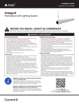
Arize® Factor
Horticulture LED Lighting System
Installation Guide
HORT150 | 99009069
BEFORE YOU BEGIN / AVANT DE COMMENCER
Read these instructions completely and carefully. Lisez attentivement ces instructions dans leur intégralité.
For Commercial or Industrial use only.
Suitable for operation in an ambient temperature as follows:
32°F-86°F (0-30°C ) for ML900, 32°F-104°F (0-40°C ) for
ML300. A mechanical ventilation or cooling system is required
to maintain the temperature as above when the lightbar is in
operation.
Convient pour un fonctionnement à une température ambiante comme suit:
0-30°C (32°F-86°F) pour ML900, 0-40°C (32°F-104°F) pour ML300. Un
système de ventilation ou de refroidissement mécanique est nécessaire pour
maintenir la température comme ci-dessus lorsque le lightbar d'éclairage est en
fonctionnement.
RISK OF SAFETY AND PRODUCT DAMAGE. DO NOT MAKE OR BREAK ELECTRICAL
CONNECTION WHILE POWER IS APPLIED.
WARNING / AVERTISSEMENT
RISK OF ELECTRIC SHOCK
• Follow appropriate lock out/tag out safety procedure.
• Properly ground electrical enclosure.
• Follow all National Electric Codes (NEC) and local codes.
•This product must be installed in accordance with the applicable
installation code by a person familiar with the construction and
operation of the product and the hazards involved.
• The installation and associated structures are subject to approval by the
authority having jurisdiction.
• Use only with components identified in this document.
• Suitable for dry, damp, and wet locations; Do not immerse any
component.
• Wear suitable Personal Protective Equipment (PPE) during installation/
maintenance. Highly recommend safety glasses, helmet and leather
glove for luminaire mounting.
RISK OF FIRE
•Minimum 3 inch distance from lightbar & driver to any combustible
material.
• Minimum 3 inch clearance between, lightbar & driver, lightbar & lightbar,
driver & driver.
• The lightbar shall be installed lens down with a minimum 6 inch distance
to anything below.
• All cables including connectors shall not be concealed or extended
through a wall, floor, ceiling, or other parts of the building structure;
located above a suspended ceiling or dropped ceiling; permanently
affixed to the building structure.
• Cables shall be routed so that they are not subject to strain and are
protected from physical damage; visible over their entire length; and
used within their rated ampacity as determined for the maximum
temperature of the installed environment specified in the instructions.
• For safe operation, and to maximize the longevity of the luminaire;
ensure that the lightbar and driver are clean and free of dirt, dust, oil, or
any other debris. Do not apply any kind of film on the lens or otherwise
cover the driver or light engine in any way.
RISQUE DE CHOC ELECTRIQUE
• Suivez la procédure de sécurité appropriée de verrouillage/étiquetage.
• Reliez correctement le boîtier électrique à la mise à la terre.
• Suivre tous les codes électriques locaux applicables.
• Ce produit doit être installé selon le code d’installation
pertinent, par une personne qui connaît bien le produit et son
fonctionnement ainsi que les risques inhérents.
• L’installation et les structures associées sont soumises à l’approbation
des autorités compétentes.
• Utilisez uniquement avec les composants identifiés dans ce document.
• Convient aux endroits secs, humides et mouillés. Ne doit pas être immergé.
• Portez les équipements de protection individuelle appropriés pendant
l’installation et la maintenance. L’utilisation de lunettes de sécurité, d’un
casque et des gants de cuir pour le montage du luminaire est fortement
recommandée.
RISQUE D’INCENDIE
• Distance minimale de 3 pouces entre l’équipement d’éclairage et toute
matière combustible.
• Distance minimale de 3 pouces entre tout équipement d’éclairage, lightbar
d’éclairage ou lightbar d’alimentation.
• Le luminaire doit être installé avec l'objectif pointé vers le bas avec une
distance minimale de 6 pouces entre le luminaire et tout objet.
• Les câbles et connecteurs ne doivent pas être dissimulés à l’intérieur, ou
passer à travers, d’un mur, d’un plancher, d’un plafond ou de toute autre
partie de la structure du bâtiment; ne doivent pas être placés au-dessus d’un
plafond suspendu; ne doivent pas faire partie intégrante de la structure du
bâtiment.
• Les câbles doivent être installés de façon à être protégés contre l’étirement
et tout autre bris physique; visibles sur toute leur longueur; utilisés dans
la limite de leur courant admissible, déterminée pour les limites de
température de l’environnement spécifiées dans le guide d’instruction.
• Pour une opération sécurisée et pour maximiser la longévité du luminaire;
S'assurer que le lightbar d'éclairage et le lightbar d'alimentation sont
propres et sans saleté, poussière, huile ou autres débris. Ne pas appliquer
tout type de film sur les lentilles et ne pas couvrir le lightbar d'alimentation
ou le lightbar d'éclairage de quelconque manière.
WARNING / AVERTISSEMENT / ADVERTENCIA
RISK OF ELECTRIC SHOCK
Turn power off before installation,
inspection, cleaning or removal.
RISQUE DE CHOC ELECTRIQUE
Coupez l'alimentation avant l'installation,
l'inspection, le nettoyage ou le retrait.
RIESGO DE SHOCK ELÉCTRICO
Apague la energía antes de la instalación,
inspección, limpieza o remoción.
LED.com
© 2023 Current Lighting Solutions, LLC. All rights reserved. GE and the GE monogram are trademarks of the
General Electric Company and are used under license. Information and specifications subject to change without
notice. All values are design or typical values when measured under laboratory conditions.
(Rev 06/20/23)
HORT150 | 99009069
Page 1 of 10
(Rev 06/19/23)
HORT150 | 99009069

Arize® Factor Installation Guide
Product Code Detailed Description Weight
Series Load
per Driver
System Watts
per Lightbar
GEHF-HPKRW1* ML900, PKR 2.6 kg (5.7lbs) 2 319W
GEHF-HPKBW1* ML900, PKB 2.6 kg (5.7lbs) 2 313W
GEHF-HPKFW1 ML900, PKF 2.6 kg (5.7lbs) 2 313W
GEHF-HBRIW1* ML900, BRI 2.6 kg (5.7lbs) 2 319W
GEHF-HBRVW1* ML900, BRV 2.6 kg (5.7lbs) 2 316W
GEHF-MPKRW1 ML300, PKR 2.6 kg (5.7lbs) 4, 5, or 6 104W
GEHF-MPKBW1 ML300, PKB 2.6 kg (5.7lbs) 4, 5, or 6 104W
GEHF-MPKFW1 ML300, PKF 2.6 kg (5.7lbs) 4, 5, or 6 106W
GEHF-MPKSW1 ML300, PKS 2.6 kg (5.7lbs) 4, 5, or 6 106W
GEHF-MBRIW1 ML300, BRI 2.6 kg (5.7lbs) 4, 5, or 6 106W
GEHF-MBRVW1 ML300, BRV 2.6 kg (5.7lbs) 4, 5, or 6 106W
GEHF-EPKBW1 ML300, PKB 2.6 kg (5.7lbs) 5, 6, 7, or 8 82W
* Risk Group 1 for photobiological per IEC 62471. All others in Exempt group.
Lightbar Specifications
1
Interconnection Cables Specifications
SKU Description Detailed Description Weight
93118692 GECA30A14-AA03B Interconnection cable greenhouse 3 feet, UL 0.16kg (0.4 lbs)
93067607 GECA30A14-AA06B Interconnection cable greenhouse 6 feet, UL 0.32kg (0.7 lbs)
3
LED Driver Specifications
Description Detailed
Description Weight
Driver Max Input Ratings
Voltage Current
GEPSC210-600D-ADGNA-D1XA1 Cord /w Leads 3.33 kg (7.3lbs) 120/208/240/277 VAC 6 / 3.5 / 3 / 2.6A
GEPSC210-600D-ADGNA-D15A1 NEMA 5-15P 3.48 kg (7.33lbs) 120 VAC 6A
GEPSC210-600D-ADGNA-D16A1 NEMA L6-15P 3.48 kg (7.33lbs) 240 VAC 3A
GEPSC210-600D-ADGNA-D17A1 NEMA L7-15P 3.48 kg (7.33lbs) 277 VAC 2.6A
GEPSC210-600G-AGJNA-D1XA1 Cord /w Leads 3.33 kg (7.3lbs) 277/347/480 VAC 2.5 / 2 / 1.5A
GEPSC210-600G-AGJNA-D17A1 NEMA L7-15P 3.48 kg (7.33lbs) 277 VAC 2.5A
2
Components
ML Series lightbars (See Lightbar Specications table on page 2 for details)
GEPSC210-600*-A**NA Series LED Driver
Optional: Interconnection cable (93118692, 93067607)
1
1
2
2
3
3
LED.com
© 2023 Current Lighting Solutions, LLC. All rights reserved. GE and the GE monogram are trademarks of the
General Electric Company and are used under license. Information and specifications subject to change
without notice. All values are design or typical values when measured under laboratory conditions.
(Rev 06/20/23)
HORT150 | 99009069
Page 2 of 10

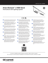
Arize® Factor Installation Guide
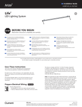
Mounting Distance
Mounting Accessories
Rolling Rack Mount, 48" (GEMB-BAW2)
Rolling Rack Mount, 24" (GEMB-BAW1)
Suspended Wire Form Support (GEMB-BANE)
4
4
5
5
6
6
39.5" Max.
15" Min.
Maximum horizontal separation
between lightbars, not using
extension cable
39.5"
Minimum vertical distance
between lightbars 15"
Mounting Accessories
SKU Description Detailed Description Weight
93153917 GEMB-BAW2 Factor rolling rack mount, 48 inch pitch 3.69 kg (8.1 lbs)
93153918 GEMB-BAW1 Factor rolling rack mount, 24 inch pitch 1.756 kg (3.86 lbs)
93153914 GEMB-BANE Factor suspended mount wireform support 0.012 kg (0.026lbs)
93153916 GEMB-FANE Factor light engine mount 3.82 kg (8.4 lbs)
95047411 GEHAK-NN-NE-N0 Driver universal 1’ remote mount kit 0.2kg (0.4 lbs)
93306044 GEHR-HAR M15 Shorting cap 0.05kg (0.11lb)
4
5
6
7
8
9
LED.com
© 2023 Current Lighting Solutions, LLC. All rights reserved. GE and the GE monogram are trademarks of the
General Electric Company and are used under license. Information and specifications subject to change
without notice. All values are design or typical values when measured under laboratory conditions.
(Rev 06/20/23)
HORT150 | 99009069
Page 3 of 10

Arize® Factor Installation Guide
ML Series Rolling Rack Mount
ML900 Rolling Rack Mount, 48"
After the horizontal bracket is attached to the strut, secure the bracket to the strut by tightening the two
screws located at each end of the bracket.
After the horizontal bracket is attached to the strut, secure the bracket to the struts by tightening the two
screws, located each end of the bracket.
ML300 Rolling Rack Mount, 24"
DC Power Input/Output
Power Input/Output
Lightbar
Lightbars
Mounting Brackets
Mounting Brackets
Driver
Driver
Tighten screws, both sides
Tighten screws, both sides
4
1
1
7
2
2
5
LED.com
© 2023 Current Lighting Solutions, LLC. All rights reserved. GE and the GE monogram are trademarks of the
General Electric Company and are used under license. Information and specifications subject to change
without notice. All values are design or typical values when measured under laboratory conditions.
(Rev 06/20/23)
HORT150 | 99009069
Page 4 of 10

Arize® Factor Installation Guide
Rolling Rack Installation Steps
Place lightbar on GEMB-BAW2 as shown, push
down with screwdriver to secure on bracket
Using two wireform supports (GEMB-BANE), the ML Series lightbar can suspended on a support structure (A) or on
cables as shown above (B and C).
Attach wireform supports by pushing up into the slots on the
underside of the lightbar.
A) Adjust screws to level the lightbar with
screwdriver. B) After lightbar is leveled, tighten
the 2 screws at the bottom.
Slots
Wireform supports
Suspended Mount Installation Steps
Cross
section view
6
1
AA
B
B
2
A B C
LED.com
© 2023 Current Lighting Solutions, LLC. All rights reserved. GE and the GE monogram are trademarks of the
General Electric Company and are used under license. Information and specifications subject to change
without notice. All values are design or typical values when measured under laboratory conditions.
(Rev 06/20/23)
HORT150 | 99009069
Page 5 of 10

Arize® Factor Installation Guide
LED Driver Bracket Mount
LED Driver Suspended Mount
ML 900 LED Driver Mounting Option A Installation
After placing driver on mounting bracket, secure driver by tightening the screws shown.
Components required: GEHAK-NN-NE-N0
Driver universal 1’ remote mount kit (95047411),
2 required.
Insert each toggle into the hole in the top of
each driver bracket.
Wrap the two toggle cables around the support
structure. Thread the toggle through the loop in
each toggle cable.
Hang the driver from the support structure.
ML300 LED Driver Mounting Option A Installation
Support
structure
8
1
3
2
4
LED.com
© 2023 Current Lighting Solutions, LLC. All rights reserved. GE and the GE monogram are trademarks of the
General Electric Company and are used under license. Information and specifications subject to change
without notice. All values are design or typical values when measured under laboratory conditions.
(Rev 06/20/23)
HORT150 | 99009069
Page 6 of 10

Arize® Factor Installation Guide
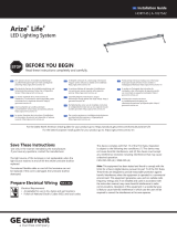
Connect the output of the driver to the first light bar using the 30”
interconnection cable. The output of first light bar (6” cable) must be connected to
the 30” cable of the 2nd lightbar, and so on.
• For ML900, only 2 lightbars should be connected as shown.
• For ML300, a minimum of 4, and a maximum of 6 light bars can be connected.
Connecting less than 4 ML300 light bars may damage the product.
• Connect the shorting cap to the last 6” lightbar cable, as shown, or else the array will
not light. The shorting cap must be secured such that it does not touch the light bar.
Shorting Cap Installation
ML900 Electrical Connection: 2 Lightbars only
ML 300 Electrical connection: 4, 5, or 6 Lightbars only
For all configurations greater than 5 bars, only use 3ft or 6ft extension cable (GECA30A14-AA03B or
GECA30A14-AA06B interconnection cables) in conjunction with LED Drivers without NEMA plugs
(GEPSC210-600D-ADGNA-D1XA1 and GEPSC210-600G-AGJNA-D1XA1).
600W
Driver
Lightbar 1
Interconnection cable
Lightbar 2
600W
Driver
Lightbar 1
Lightbar 3
Lightbar 2
Lightbar 4
Lightbar 5
Lightbar 6
ML300
ML900
RISK OF SAFETY AND PRODUCT DAMAGE. DO NOT MAKE OR BREAK
ELECTRICAL CONNECTION WHILE POWER IS APPLIED.
Shorting Cap
9
1
1
1
1
1
1
1
1
2
2
Shorting Cap
9
Shorting Cap
9
3
LED.com
© 2023 Current Lighting Solutions, LLC. All rights reserved. GE and the GE monogram are trademarks of the
General Electric Company and are used under license. Information and specifications subject to change
without notice. All values are design or typical values when measured under laboratory conditions.
(Rev 06/20/23)
HORT150 | 99009069
Page 7 of 10

Arize® Factor Installation Guide
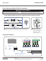
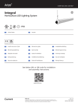
Connect the green wire
to the incoming ground
conductor. Connect the black
wire to Line 1 and white
wires to Neutral or Line 2 of
the incoming AC line.
AC line
To driver
input
Male
Lightbar
Secure locknut
Driver
Female
Mate male connector from lightbar with female connector from DC output of
driver. Ensure matching up the key guides from Male to Female connector.
Driver Output and Lightbar Electrical Connections
1 2
DO NOT MAKE OR BREAK ELECTRICAL CONNECTION WHILE POWER IS APPLIED.
Connection Schematic
Driver Input Wire Colors
Black = Line 1
White = Neutral or Line 2
Yellow/Green = Ground
Optional 3’or 6’ interconnection cable
NOTE: Maximum cumulative length of
interconnection cable is 6 feet.
*White = Neutral or Line 2
* * *
Driver Driver Driver Driver
N
3-Phase Y
REPEAT FOR ENTIRE CIRCUIT BALANCING OUT EACH PHASE
3-Phase ∆
L3
L2
L1
Driver Driver
Green
Green
Green
Green
Green
Green
Black
Black
Black
Black
Black
Black
White
White
White
White
White
White
WARNING / AVERTISSEMENT
RISK OF ELECTRIC SHOCK OR PRODUCT DAMAGE
Turn power OFF before inspection, installation or removal.
RISQUE DE CHOC ÉLECTRIQUE OU DE DOMMAGE AU PRODUIT
Coupez l’alimentation avant l’inspection, l’installation ou la désinstallation.
Key
AC line
Use proper circuit
protection level
3
1
2
Lightbar
Lightbar
LED.com
© 2023 Current Lighting Solutions, LLC. All rights reserved. GE and the GE monogram are trademarks of the
General Electric Company and are used under license. Information and specifications subject to change
without notice. All values are design or typical values when measured under laboratory conditions.
(Rev 06/20/23)
HORT150 | 99009069
Page 8 of 10

Arize® Factor Installation Guide
Wired Dimming Connections (Optional)
Junction Box Cover Removal
• Using a #1 Phillips screwdriver, unscrew the 6
screws on the junction box cover.
• Remove the junction box cover from the junction
box enclosure.
NOTE: Be sure to hold on to the screws, junction box
cover, and gasket for future use.
Wall Dimming Wire Insertion
• Remove the sealed gland in the bottom of the
junction box enclosure, and install an appropriate
Listed ½” NPT fitting rated for the environment into
the open threaded open conduit connection.
• Bring the conductors for the building dimming
network into this fitting.
NOTE: Customer is responsible for the 1/2'' NPT- 14
thread per inch tting.
Wire Dimming Electrical Connections
• 3A - For Drivers Prior 2021
Connect the appropriate wiring to Dim + (0-10V) and
Dim – (0-10V) from driver. Insulate the black-white,
pink and blue-white wires. Follow dimming switch
instructions for rest of connection.
• 3B - For Drivers After 2021
Connect the appropriate wiring to Dim + (0-10V) and
Dim – (0-10V) from driver. Insulate the black-white,
white-purple, and blue-white wires. Follow dimming
switch instructions for rest of connection.
Junction Box Cover Replacement
• Ensure gasket is sitting in place on the inner edge of
the junction box cover.
• Fasten all 6 screws to ensure water tight seal.
NOTE: Be careful not to strip out the junction box
enclosure by over tightening the screws.
For Drivers Prior 2021 For Drivers After 2021
3B3A
Driver Driver
Dimming
Switch
Dimming
Switch
Purple
Purple
Blue-White
Blue-White
Pink
White-Purple
Black-White
Black-White
Gray
Pink
+ (0-10V)
+ (0-10V)
– (0-10V)
– (0-10V)
Gasket in cover
1
3
2
4
NOTE: Arize Factor dimming allows user to adjust the light output from 0%/10-100%. When set to 0%, the system will enter standby mode,
consuming 0.5-1.5W and LEDs may remain very faintly lit. If 0 light is preferred, switch o the unit via the mains (AC line).
Remove cover Dimming In
AC input
Remove screws
To lightbar
WARNING / AVERTISSEMENT
RISK OF ELECTRIC SHOCK OR PRODUCT DAMAGE
• Turn power off before installation, inspection, cleaning or
removal. Follow appropriate lock out/tag out safety procedure.
• This product must be installed in accordance with the
applicable installation code by a person familiar with
the construction and operation of the product and the
hazards involved.
RISQUE DE CHOC ÉLECTRIQUE OU DE DOMMAGE AU PRODUIT
• Coupez l’alimentation avant l’inspection, l’installation ou la
désinstallation. Suivez la procédure de sécurité appropriée de
verrouillage/étiquetage.
• Ce produit doit être installé selon le code d’installation
pertinent, par une personne qui connaît bien le produit et son
fonctionnement ainsi que les risques inhérents.
LED.com
© 2023 Current Lighting Solutions, LLC. All rights reserved. GE and the GE monogram are trademarks of the
General Electric Company and are used under license. Information and specifications subject to change
without notice. All values are design or typical values when measured under laboratory conditions.
(Rev 06/20/23)
HORT150 | 99009069
Page 9 of 10

Arize® Factor Installation Guide
Electrical products must not be thrown out with domestic waste. They must be taken to
a communal collecting point for environmentally friendly disposal in accordance with
local regulations. Contact your local authorities or stockist for advice on recycling. The
packaging material is recyclable. Dispose of the packaging in an environmentally friendly
manner and make it available for the recyclable material collection-service.
RISK GROUP 1 - CAUTION / ATTENTION - RAYONNEMENT LUMINEUX GROUPE 1*
Possibly hazardous optical radiation emitted from this product. Do not stare at operating lamp. May be harmful to the eyes.
Le rayonnement lumineux émis par ce produit est potentiellement dangereux. Ne pas regarder la lumière émise
directement car elle pourrait occasionner des dommages aux yeux.
For the latest install guides for your product go to:
LED.com/hort
* See Specification Table for Risk Group 1 models.
• These photobiological safety markings are based on testing of the light output characteristic of a single horticultural luminaire.
Increased exposure risk to facility personnel may be present depending upon the number of horticultural luminaires and their
placement and/or positioning within the plant growth facility.
• It is the responsibility of the plant growth facility to address these risks at the facility level and to ensure that people entering the
plant growth areas while the lights are on, are aware of these risks and that appropriate safeguards are in place.
• Ces avertissements de sécurité photobiologiques sont basés sur des tests du rendement lumineux d'un seul luminaire horticole.
Les employés risquent de souffrir d'une exposition accrue selon le nombre de luminaires horticoles et leur placement et / ou
positionnement au sein de la serre / chambre de culture.
• Il relève de la responsabilité de l'opérateur de l'installation de gérer les risques au niveau de l'installation et de s'assurer que les
personnes qui pénètrent dans les zones de croissance des plantes pendant que les lumières sont allumées soient conscientes des
risques et que des mesures de protection appropriées soient en place.
Save These Instructions
Use only in the manner intended by the manufacturer. If you have any questions, contact the manufacturer.
This device complies with part 15 of the FCC Rules. Operation is subject to the following two conditions: (1) This device may not cause harmful interference,
and (2) this device must accept any interference received, including interference that may cause undesired operation.
NOTE: This equipment has been tested and found to comply with the limits for a Class A digital device, pursuant to part 15 of the FCC Rules. These limits
are designed to provide reasonable protection against harmful interference when the equipment is operated in a commercial environment. This equipment
generates, uses, and can radiate radio frequency energy and, if not installed and used in accordance with the instruction manual, may cause harmful
interference to radio communications. Operation of this equipment in a residential area is likely to cause harmful interference in which case the user will be
required to correct the interference at his own expense.
This Class [A] RFLD complies with the Canadian standard ICES-005. /CeDEFR de la classe [A] est conforme à la NMB-005 du Canada.
Scan the QR code for the English
and Spanish installation guide/
Escanear el código QR para la guía
de instalación Español
Visit LED.com
Call us today! 1-833-733-9243
Email us:
Current Lighting Solutions, LLC
Beachwood, OH 44122
LED.com
© 2023 Current Lighting Solutions, LLC. All rights reserved. GE and the GE monogram are trademarks of the
General Electric Company and are used under license. Information and specifications subject to change without
notice. All values are design or typical values when measured under laboratory conditions.
(Rev 06/20/23)
HORT150 | 99009069
Page 10 of 10
-
 1
1
-
 2
2
-
 3
3
-
 4
4
-
 5
5
-
 6
6
-
 7
7
-
 8
8
-
 9
9
-
 10
10


ARIZE Factor Vertical Farming Guide d'installation
- Taper
- Guide d'installation
dans d''autres langues
Documents connexes
-
 ARIZE Factor Vertical Farming Troubleshooting guide
-
 ARIZE Element L400 Guide d'installation
-
 ARIZE Element L1000 Gen 2 Guide d'installation
-
 ARIZE HORT166 Manuel utilisateur
-
ARIZE L1000 Manuel utilisateur
-
 ARIZE Life² Guide d'installation
-
 ARIZE Life2 LED Lighting System Guide d'installation
-
 ARIZE Integral Guide d'installation


Autres documents
-
GE current HORT161 Guide d'installation
-
GE current RUL-Series Guide d'installation
-
 SloanLED 701666 Guide d'installation
-
Maxim Lighting 88950WT Manuel utilisateur
-
-
Lumination RUL Series LED Refit Universal Linear Kit Guide d'installation
-
GE Horticulture Guide d'installation
-
 GE current HORT158 Manuel utilisateur
-
Maxim Lighting 88960WT Manuel utilisateur
-
Current Arize Element L1000 Gen 2 Guide d'installation

