Rupes GM62N Angular Grinders Manuel utilisateur
- Taper
- Manuel utilisateur

GM62N - GM81N
GL41N - GL51N
Smerigliatrici angolari
Angular grinders
Meuleuses angulaires
Winkelschleifer
Amoladoras angulares
Haakse slijpers
Угловые шлифовальные машины
ISTRUZIONI ORIGINALI PER L'USO E LA MANUTENZIONE
TRANSLATION OF ORIGINAL OPERATING INSTRUCTION
CONVERSION DES INSTRUCTIONS DE FONCTIONNEMENT ORIGINAL
ÜBERSETZUNG DES URSPRÜNGLICHEN BEDIENUNGSANLEITUNG
TRADUCCIÓN DE MANUAL DE INSTRUCCIONES ORIGINAL
VERTALING VAN ORIGINELE GEBRUIKSAANWIJZING
ПЕРЕВОД ИНСТРУКЦИИ ПО ЭКСПЛУАТАЦИИ

3
2
5
9
10
8
12
4
12
7
6
11
3
2
12
1
GM62N
1 2 34

4
8
12
16
20
24
28
Leggere tutte queste istruzioni prima di azionare il
presente prodotto
.
Indicazioni importanti per la sicurezza dell’utilizzatore
Lesen Sie zuerst die folgenden Anweisung bevor Sie das
Gerät bedienen.
Wichtige Sicherheitsangaben
Antes de accionar este producto es necesario leer todas
estas instrucciones
Indicaciones importantes para la seguridad del usuario
Lees de volgende instructie voor u het product gebruikt
Belangrijke veiligheids instructies
Следует прочитать все эти инструкции прежде, чем
приводить овку.
Важные указания для безопасности пользователя
Lire toutes ces instructions avant d’actionner
le présent produit.
Indications importantes pour la sécurité de l’utilisateur
Read the following instruction first before operate
the product
Important safety indications
ISTRUZIONI ORIGINALI PER L'USO
E LA MANUTENZIONE
TRANSLATION OF ORIGINAL
OPERATING INSTRUCTION
CONVERSION DES INSTRUCTIONS
DE FONCTIONNEMENT ORIGINAL
ÜBERSETZUNG DES URSPRÜNGLICHEN
BEDIENUNGSANLEITUNG
TRADUCCIÓN DE MANUAL DE
INSTRUCCIONES ORIGINAL
VERTALING VAN ORIGINELE
GEBRUIKSAANWIJZING
ПЕРЕВОД ИНСТРУКЦИИ ПО
ЭКСПЛУАТАЦИИ

4
AVVERTENZE GENERALI
Le istruzioni per la sicurezza e la prevenzione degli infortuni sono
riportate nel fascicolo “INDICAZIONI PER LA SICUREZZA” che costituisce
parte integrante della presente documentazione. Il presente MANUALE
D’ISTRUZIONI per l’uso riporta solamente le informazioni aggiuntive
strettamente correlate all’uso specifico della macchina.
UTILIZZO CONFORME AGLI SCOPI PREVISTI
Questo utensile è destinato a funzionare come smerigliatrice. Leggere tutti
gli avvertimenti di sicurezza, le istruzioni, le illustrazioni e le specifiche
forniti con questo utensile. Il mancato rispetto di tutte le istruzioni sotto ripor-
tate può causare una scossa elettrica, un incendio e/o un incidente grave.
Le operazioni di levigatura, spazzolatura metallica e lucidatura non sono
consigliate con questo utensile. Le operazioni per le quali non è previsto
l’utensile possono provocare un pericolo e causare danni alle persone.
Non utilizzare accessori non specificatamente realizzati per l’uso previsto
o non consigliati dal produttore. Il semplice fatto che l’accessorio possa
essere fissato al vostro utensile non garantisce un funzionamento in tutta
sicurezza.
La velocità nominale dell’accessorio deve essere almeno pari alla velocità
massima indicata sull’utensile. Gli accessori fatti funzionare a una velocità
superiore a quella nominale possono rompersi ed essere proiettati in aria.
Il diametro esterno e lo spessore del vostro accessorio devono essere
adatti alle caratteristiche di capacità della protezione di sicurezza del vostro
utensile. Gli accessori che hanno dimensioni non corrette non possono essere
protetti o controllati adeguatamente.
La conformazione delle mole o di qualsiasi altro accessorio deve adattarsi
correttamente al mandrino dell’utensile. Gli accessori dotati di fori dell’albero
che non corrispondono agli elementi di montaggio sull’utensile non
rimarranno in equilibrio, vibreranno eccessivamente e potranno provocare una
perdita di controllo.
Non usare un accessorio danneggiato. Prima di ogni utilizzo esaminare gli
accessori, quali le mole abrasive, per evidenziare la presenza eventuale di
scheggiature o di incrinature. Se l’utensile o l’accessorio ha subito una
caduta, esaminare i danni eventuali o installare un accessorio non
danneggiato. Dopo aver esaminato e installato un accessorio, mettetevi,
insieme alle persone presenti, a una distanza di sicurezza dall’accessorio
rotante e fate funzionare l’utensile alla velocità massima a vuoto per un
minuto. Gli accessori danneggiati si romperanno in genere in questo periodo di
prova.
4
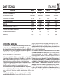
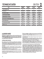
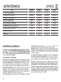
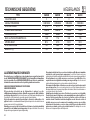
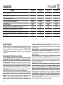
MODELLO GM62N GM81N GL41N GL51N
CLASSE DI ISOLAMENTO II II II II
TENSIONE DI LAVORO 230V-50Hz 230V-50Hz 230V-50Hz 230V-50Hz
CORRENTE ASSORBITA 9,7 A 9,7 A 5,8 A 5,8 A
POTENZA ASSORBITA 2.000 W 2.000 W 1.200 W 1.200 W
GIRI/min 6.000 8.000 4.000 5.500
DIAMETRO MAX. DELLA MOLA mm 230 178 230 178
FILETTATURA ALBERO MANDRINO M 14 M 14 M 14 M 14
FERMO ALBERO
MANDRINO SI NO NO NO
MASSA Kg 4,2 4,2 3,8 3,8
DATI TECNICI ITALIANO

5
AVVERTENZEDI SICUREZZA SPECIFICHE PER LE OPERAZIONI DI MOLATURA E
DI TAGLIO ABRASIVO
Utilizzare unicamente tipi di mola consigliati per il vostro utensile e la protezione spe-
cifica concepita per la mola scelta. Le mole per le quali non è stato concepito l’utensile
non possono essere protette in modo soddisfacente e non sono sicure.
La protezione deve essere solidamente fissata all’utensile e messa in posizione di si-
curezza massima, di modo che l’operatore sia esposto il meno possibile alla mola. La
protezione permette di proteggere l’operatore dai frammenti di mola rotta e da un contatto
accidentale con la mola.
Le mole devono essere utilizzate solo per le applicazioni raccomandate. Per esempio:
non smerigliare con il lato della mola da taglio. Le mole abrasive da taglio sono destinate
alla molatura periferica, l’applicazione di forze laterali a queste mole può farle rompere.
Usare sempre flange per mola non danneggiate e che siano di dimensione e forma
corrette per la mola che avete scelto. Le flange per mola appropriate sorreggono la mola,
riducendo così la possibilità di rottura della mola.
Le flange per mole da taglio possono essere diverse dalle flange per mola da smeri-
gliatura. Non utilizzare mole usate di utensili più grandi. La mola destinata a un utensile
più grande non è adatta a causa delle velocità più elevata di un utensile più piccolo: la mola
può esplodere.
Non “mandare in blocco” la mola da taglio né applicare una pressione eccessiva. Non
tentare di rendere il taglio eccessivamente profondo. Una forte pressione sulla mola au-
menta il carico e la probabilità di torsione o di piegamento della mola nel taglio e la possibi-
lità di contraccolpo o di rottura della mola.
Non mettetevi allineati alla mola in rotazione, neppure dietro di essa. Quando la mola,
nel momento in cui funziona, si allontana dal vostro corpo, l’eventuale contraccolpo può
spingere la mola in rotazione, insieme all’utensile, direttamente verso di voi.
Quando la mola si piega o quando si interrompe il taglio per una qualsiasi ragione,
staccare l’utensile dall’alimentazione e tenerlo immobile sino a che la mola non si sia
completamente fermata. Non cercare mai di togliere la mola da taglio mentre la mola è in
movimento altrimenti potrebbe verificarsi un contraccolpo. Bisogna risalire alle cause del
piegamento della mola e prendere le misure correttive affinché non si verifichi più.
Non riprendere l’operazione di taglio nel pezzo in lavorazione. Lasciare che la mola
raggiunga la sua velocità piena e rientrare con attenzione nel taglio. La mola si può
bloccare, risalire oppure avere un contraccolpo se l’utensile viene riavviato nel pezzo in la-
vorazione.
Prevedere un supporto per i pannelli o per qualsiasi pezzo di grosse dimensioni in la-
vorazione per ridurre al minimo il rischio di incastro e di contraccolpo della mola. I pez-
zi in lavorazione grandi hanno la tendenza a flettersi sotto il loro stesso peso. I supporti de-
vono essere messi sotto il pezzo in lavorazione, vicino alla linea di taglio e vicino al bordo del
pezzo in lavorazione su entrambi i lati della mola.
Siate particolarmente prudenti quando fate un “taglio a tasca” in pareti esistenti o in al-
tre zone senza visibilità. La mola sporgente può tagliare tubi del gas o dell’acqua, cavi elet-
trici o oggetti causando possibili contraccolpi.
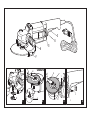
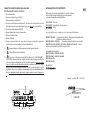
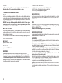
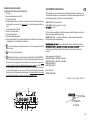
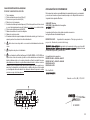
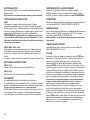
PARTI DELLA MACCHINA
1 - Etichetta di identificazione
2 - Leva dell’interruttore
3 - Blocco dell’interruttore
4 - Pulsante di bloccaggio albero mandrino (solo GM62N)
5 - Albero mandrino
6 - Impugnatura ausiliaria
7 - Protezione orientabile
8 - Collare per fissaggio della protezione
9 - Distanziale
10 - Ghiera di fissaggio
11 - Feritorie per ventilazione motore
12 - Chiavi di servizio
MESSA IN FUNZIONE
Prima di mettere in funzione la macchina accertarsi che:
- l’imballo sia integro e non mostri segni di danneggiamento dovuti a trasporto e magazzi-
naggio;
- la macchina sia completa; controllare che numero e natura dei componenti siano conformi
a quanto riportato sul presente libretto;
- la fonte di energia e le prese di corrente a disposizione possano sopportare il carico indi-
cato in tabella e riportato sulla targhetta di identificazione della macchina il cui facsimile,
con spiegazioni, è riportato a pag. 7.
MONTAGGIO DELLA MACCHINA
- Avvitare l’impugnatura ausiliaria (6) in uno dei due fori predisposti sulla scatola ingranaggi,
la stessa può essere posizionata sia a destra che a sinistra del corpo macchina;
- montare la protezione sul corpo macchina a mezzo del collare (8) e bloccarla serrando
l’apposita vite.
La protezione deve essere montata in corrispondenza dell’impugnatura.
MONTAGGIO DELLA MOLA ABRASIVA
1. Inserire il distanziale (9);
2. inserire la mola abrasiva;
3. avvitare e serrare la ghiera di fissaggio (10) con la chiave a pioli mantenendo fermo l’al-
bero mandrino con la chiave da 17 mm o col pulsante di bloccaggio albero mandrino
(solo GM62N).
PRIMA DELLA MESSA IN SERVIZIO
Accertarsi che:
- la fonte di energia sia conforme alle caratteristiche della macchina;
- il cavo di alimentazione e relativa spina siano in perfetto stato;
- l'interruttore di inserimento/disinserimento sia efficiente operando, però, a spina disinserita;
- il pulsante di bloccaggio dell’albero mandrino (GM62N) (4) sia disinserito (ruotare a mano
la mola per almeno un giro);
- tutti i componenti della macchina siano montati correttamente e non presentino segni di
danneggiamento;
- le feritoie di ventilazione non siano ostruite.
AVVIAMENTO E FERMATA
- Avviamento: Spingere in avanti il blocco dell’interruttore (3) verso il corpo della macchina;
premere contemporaneamente la leva dell’interruttore (2) verso l’alto (fig. 4), così facendo
l’interruttore rimane bloccato in funzione.
- Fermata: premere la leva dell’interruttore (2) verso l’alto in modo da rilasciare il blocco del-
l’interruttore (3).

6
FUNZIONAMENTO DI PROVA
Avviare la macchina e controllare che non siano presenti vibrazioni anomale o scentrature
della mola.
In caso contrario spegnere la macchina immediatamente e provvedere ad eliminare le
anomalie.
SMONTAGGIO E SOSTITUZIONE DELLE MOLE ABRASIVE
GM62N
Bloccare l'albero mandrino spingendo il pulsante (4) facendo contemporaneamente ruota-
re la mola finchè se ne avverta il blocco. Svitare la ghiera con la chiave a pioli, sostituire la
mola, riavvitare e serrare. Liberare l'albero mandrino rilasciando il pulsante e far ruotare a
mano la mola per controllarne l'avvenuto sbloccaggio.
AVVERTENZA!: il pulsante di bloccaggio dell’albero mandrino non deve mai essere
premuto prima che l'utensile non sia completamente fermo, pena la rottura della sca-
tola ingranaggi o del perno del pulsante e al conseguente decadimento della garanzia.
GM62N - GM81N - GL41N - GL51N
Per bloccare l'albero mandrino inserire la chiave da 17 mm nella tacca dell'albero tra mola e
scatola ingranaggi. Svitare la ghiera con la chiave a pioli, sostituire la mola, riavvitare e serra-
re.
Non sono ammessi altri attrezzi per il serragio/disserraggio
UTENSILI DI LAVORO AMMESSI
GM81N - GL51N
Mole abrasive a centro depresso Ø 178 mm.
GM62N - GL41N
Mole abrasive a centro depresso Ø 230 mm.
MANUTENZIONE
Tutte le operazioni vanno eseguite a spina disinserita.
A fine lavoro, od in caso di necessità, spolverare con getto di aria compressa il corpo mac-
china prestando particolare attenzione alla pulizia delle feritoie di ventilazione del motore.
Non sono ammessi altri interventi da parte dell'utente.
Per la manutenzione e la periodica pulizia delle parti interne, come spazzole, cuscinetti, in-
granaggi etc. o altre necessità rivolgersi ai Centri di Assistenza autorizzati.
SICUREZZA ELETTRICA - BASSA TENSIONE
Le prove/verifiche sono state eseguite in accordo alle norme:
EN 60745-1 sicurezza degli utensili elettrici a motore portatili
EN 60745-2-3 norme particolari per smerigliatrici.
SCHERMATURA CONTRO I RADIODISTURBI
Le macchine sono conformi agli effetti della prevenzione ed eliminazione dei radiodisturbi
misurati secondo le norme EN55014-1+ EN55014-2; EN61000-3-2+EN61000-3-3.
FORMAZIONE DI RUMORE
Il livello di pressione sonora, al posto di lavoro, generato dalla macchina in condizioni nor-
mali è di 88,7 dB (A) - potenza sonora 99,7 dB (A) - misurati secondo le norme EN ISO 3744
+ UNI EN ISO 11202.
Attenzione: indossare adeguati presidi per la difesa dell'udito! (vedi avvertenze gene-
rali).
VALORE MEDIO DELL'ACCELERAZIONE
Il valore quadratico medio dell'accelerazione è inferiore a 2,5 m/sec
2
misurati secondo le
norme UNI EN28662 + UNI EN ISO 5349.
GARANZIA
Tutte le macchine costruite dalla RUPES sono garantite per 12 mesi dalla data di acquisto
contro difetti di materiale e di fabbricazione.
Le macchine devono essere utilizzate esclusivamente con accessori e ricambi originali
RUPES: si declina ogni responsabilità per danni o incidenti provocati dall’inosservanza del-
la presente norma che causa anche il decadimento della garanzia.
La garanzia decade qualora non vengano rispettate le prescrizioni del presente libretto o
qualora venga fatto uso improprio della macchina. Decade altresì se la macchina viene
smontata o manomessa o se vi sono evidenti danni derivanti da cattiva cura della stessa. La
garanzia è subordinata alla compilazione del tagliando riportato sull’ultima pagina di
copertina del presente libretto d'istruzioni.
In caso di accertato malfunzionamento la macchina, accompagnata dal certificato di garan-
zia, dovrà essere consegnata o spedita franco di porto, non smontata e nell'imballo origina-
le, al fabbricante o ad un Centro di Assistenza autorizzato riportato nell'elenco allegato al
presente libretto.
In ogni caso la garanzia non dà diritto alla sostituzione della macchina.
La RUPES si riserva di apportare qualsiasi modifica alle caratteristiche tecniche o estetiche
dei propri prodotti senza preavviso.
Non si assume nessuna responsabilità per eventuali errori di stampa. Il presente stampato
annulla e sostituisce i precedenti.

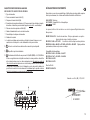
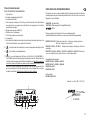
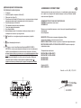
TARGHETTA DI IDENTIFICAZIONE DELLA MACCHINA
POSIZIONAMENTO E SIGNIFICATO DEI DATI
1. Tipo della macchina.
2. Tensione nominale di lavoro in Volt (V).
3. Frequenza di lavoro in Hertz (Hz).
4. Corrente assorbita espressa in Ampere (A). Accertarsi che la linea elettrica cui viene
allacciata la macchina possa agevolmente sopportare almeno la corrente indicata.
5. Potenza assorbita espressa in Watt (W).
6. Numero di matricola o di serie della macchina.
7. Dati tecnici della macchina.
8. Numero di giri/min.
9. Il doppio quadrato indica che la macchina è in doppio isolamento e quindi non
necessita di messa a terra tramite il cordone di alimentazione.
10. Leggere tutte queste istruzioni prima di azionare il presente prodotto.
11. Dispositivi di protezione individuale.
12. Il prodotto, in ottemperanza alla Direttiva Europea 2002/96/CE (RAEE) +
2003/108/CE e alla sua attuazione nel diritto nazionale, quando giunge a fine vita, non
deve essere disperso nell’ambiente o gettato tra i rifiuti domestici, ma deve esse smalti-
to presso i centri di raccolta differenziata autorizzati (contattare le autorità locali compe-
tenti per conoscere dove smaltire il prodotto secondo le norme di legge). Il corretto
smaltimento del prodotto contribuisce alla tutela della salute e alla salvaguardia dell’am-
biente. Lo smaltimento abusivo del prodotto comporta sanzioni a carico dei trasgresso-
ri.
IL PRESIDENTE
G. Valentini
DICHIARAZIONE DI CONFORMITÀ
Dichiariamo sotto la nostra responsabilità che l’utensile elettrico a
motore portatile, al quale fa riferimento il presente manuale, è
conforme ai Requsiti Essenziali delle Direttive:
2006/42/CE Macchine
2014/30/UE Compatibilità elettromagnetica
2011/65/UE RoHS
Le prove/verifiche sono eseguite in accordo alle seguenti Normative:
EN ISO 12100: 2010 Sicurezza del macchinario – Principi generali di progettazione –
Valutazione e riduzione del rischio
EN 60745-1:2009 + A11:2010 Sicurezza degli utensili elettrici a motore portatili
EN 60745-2-3: 2009 + A2:2013 + A11:2014 + A12:2014 + A13:2015 Norme
particolari per smerigliatrici, lucidatrici e levigatrici a disco
Compatibilità elettromagnetica:
EN 55014-1:2006 + A1:2009 + A2:2011
EN 55014-2:1997 + A1:2001 + A2:2008
EN 61000-3-2:2014
EN 61000-3-3:2013
Direttiva RoHS:
EN IEC 63000:2018
Vermezzo con Zelo (MI), 01/12/2021
S.p.A a socio unico

8
GENERAL WARNINGS
All instructions concerning safety and the prevention of industrial accidents can be
found in file SAFETY INSTRUCTIONS, that forms integral part of this
documentation. This INSTRUCTION MANUAL only contains additional information
that specifically explain how to use the machine.
SPECIFIC USE
This tool is designed to be used as grinder. Refer to all the safety warnings,
instructions, illustrations and specifications supplied with the tool. Failure to follow
all the instructions provided below may result in electric shocks, fires and/or serious
injuries.
Theuse of this tool for smoothing, metal brushing and polishing operations is not
recommended. Its use for applications other than those for which it has been designed
may lead to hazardous situations and cause injuries to people.
Do not use accessories that are not specifically designed for the intended use of
the tool or that have not been recommended by the manufacturer. The fact that an
accessory can be fixed to the tool does not imply that it can be used safely.
The rated speed of accessories must be at least equivalent to the maximum speed
of the tool. If operated at a greater speed than the rated one, accessories may break and
cause the ejection of chips.
The external diameter and thickness of accessories must be appropriate to
guarantee the protection and safety of the tool. Accessories with incorrect dimensions
cannot be adequately protected or controlled.
The configuration of the cutting/grinding wheels or any other accessory must
perfectly adapt to the tool spindle. Accessories with holes that cannot be aligned with
the fitting components on the tools will cause unbalance, excessive vibrations and may
be difficult to control.
Do not use an accessory if damaged. Before use, inspect all the accessories, like
the abrasive cutting/grinding wheels, in order to verify that they are not cracked or
splintered. If the tool or accessory has fallen, verify that they are not damaged and,
if necessary, replace it with a new one. After inspecting or installing an accessory,
move to a safe distance with any other person present and operate the tool at
maximum speed without load for one minute. Damaged accessories generally break
during this test period.
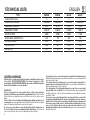
TYPE GM62N GM81N GL41N GL51N
INSULATION CLASS II II II II
OPERATING VOLTAGE 230V-50Hz 230V-50Hz 230V-50Hz 230V-50Hz
ABSORBED CURRENT 9,7 A 9,7 A 5,8 A 5,8 A
ABSORBED POWER 2.000 W 2.000 W 1.200 W 1.200 W
ROTATION RPM 6.000 8.000 4.000 5.500
WHEEL MAX. DIAMETER mm 230 178 230 178
SPINDLE THREAD M 14 M 14 M 14 M 14
SPINDLE STOP YESNO NO NO
WEIGHT Kg 4,2 4,2 3,8 3,8
TECHNICAL DATA ENGLISH 8

9
WARNINGS SPECIFICALLY RELATED TO GRINDING AND ABRASIVE CUTTING
OPERATIONS
Use only the type of cutting/grinding wheels recommended for your tool and the
protection specifically designed for the selected cutting/grinding wheel.
Cutting/grinding wheels not designed to be used with the tool cannot be adequately
protected and are unsafe.
The protection must be solidly fixed to the tool and placed in the safest position
possible so as to minimise the potential risk of contact between the operator and
cutting/grinding wheel. The protection is designed to protect operators from the ejection of
fragments in case of breakage and from accidental contacts with the grinding wheel.
Cutting/grinding wheels must be used for the recommended applications only. For
example do not use the cutting side of the wheel for grinding operations. Abrasive
cutting wheels may break because they are designed to be used for peripheral grinding
operations and for the application of lateral forces.
Always use the cutting/grinding wheels with undamaged flanges and verify that their
shape and dimensions are appropriate for the selected cutting/grinding wheel. The
purpose of flanges is to support the cutting/grinding wheel and reduce the potential
risk of breakage.
Flanges for cutting wheels may be different from those of grinding wheels. Do not use
grinding/cutting wheels that have been fitted on larger tools. These cutting/grinding
wheels are unsuitable because of their higher speed as compared to that of smaller tools
and could therefore cause explosions.
Do not “stall” the cutting wheel or apply an excessive pressure. Do not attempt to
increase the cutting depth. The application of a high pressure on the cutting wheel
increases the load and the risk of torsion and bending during cutting, with the consequent
risk of rebound forces or breakage.
Do not stand in line with the cutting/grinding wheel or behind it while it is rotating.
When the cutting/grinding wheel moves away from the operator’s body during operation,
the rebound force may push the revolving cutting/grinding wheel and the tool towards the
operator.
If the cutting/grinding wheel bends or the cutting operations stops for any reason,
disconnect the tool from the power supply and keep it still until the cutting/grinding
wheel has come to a full stop. Do not attempt to remove the cutting wheel while it is
moving because this could produce a rebound force. Identify the cause of the problem and
perform the necessary corrective actions to prevent the problem from reoccurring.
Do not resume the cutting operation. Resume the cutting operation only when the
cutting wheel has reached its maximum speed. The cutting wheel may stall, lift or
produce a rebound force if the tool is restarted when the work piece is present.
Always use appropriate supports for panels or large work pieces in order to minimise
the risk of interlocking and rebound forces. Large work pieces tend to bend because of
their weight. Supports must therefore be placed under the work piece, close to the cutting
line and to the edge of the work piece on both sides.
Pay particular attention when cutting “pockets” on existing walls or other areas with
limited visibility. The projecting cutting wheel may cut gas or water pipes, electrical cables
or other objects and thus produce a rebound force.
PARTS OF THE TOOL
1 - Identification plate
2 - Switch lever
3 - Switch block
4 - Spindle locking button (GM62N only)
5 - Spindle
6 - Auxiliary handle
7 - Adjustable guard
8 - Collar for fixing for the protective
9 - Spacer
10 - Locking ring
11 - Motor ventilation slots
12 - Wrenches
STARTING UP
Before starting-up the tool, ensure that:
- the packaging is complete and does not show signs of having been damaged during sto-
rage or transport;
- the tool is complete; check that the number and type of components comply with that re-
ported in this instruction booklet;
- the power supply and socket outlet can support the load reported in the table and that in-
dicated on the tool identification plate reproduced and explained on page 11.
ASSEMBLING THE TOOL
-Screw the auxiliary handle (6) in one of the holes on the gearbox, the handle can be
mounted on the left or right of the tool body.
- fit the guard on the body of the tool using the collar (8).
Lock it in position by tightening the screw.
The guard must be mounted level with the handle.
FITTING ABRASIVE WHEEL
1. Insert the spacer (9);
2. insert the abrasive wheel;
3. screw and tighten the lock nut (10) using the pin wrench, preventing the spindle form
moving using the 17 mm. spanner or the spindle locking button (GM62N only).
BEFORE STARTING THE TOOL
Ensure that:
- the power supply conforms with the characteristics of the tool;
- the power supply cable and plug are in perfect condition;
- the ON/OFF switch works properly though with the power supply disconnected;
- the spindle locking button (GM62N) (4) is released (rotate the abrasive wheel by hand for
at least one revolution);
- all the parts of the tool have been assembled in the proper manner and that there are no
signs of damage;
- the ventilation slots are not obstructed.
STARTING AND STOPPING
-Starting: push the switch block (3) forward towards the body of the machine and simulta-
neously push the switch lever (2) up (fig. 4) in order to lock the switch in operating position.
-Stopping: push the switch lever (2) up in order to release the switch block (3).

10
TEST RUN
Start the tool and check that there are no unusual vibration, no dismatching of the wheel.
Otherwise switch-off the tool immediately and eliminate the cause.
FITTING AND REPLACING ABRASIVE WHEELS
GM62N
Lock the wheel spindle by pressing button (4), while at the same time rotating thewheel until
it locks position. Unscrew the locking ring using the pin wrench, replace the wheel, re-tighten
the locking ring. Unlock the wheel spindle by releasing the buttonand rotate the wheel by
hand to ensure that it runs freely.
WARNING!: never press the wheel spindle locking button until the tool has stopped
moving and is perfectly stationary; the gear box or the push button pin could be
broken and the guarantee would be invalidated.
GM62 - GM81 - GL41 - GL51
Lock the wheel spindle by inserting the 17 mm spanner in the nocth in the spindle between
the wheel and the gearbox. Unscrew the locking ring using the pin wrench, replace the
wheel, re-tighten the locking ring.
Tools other than those mentioned must not be used for slackening or tightening purposes.
USABLE ABRASIVE WHEELS
GM81N - GL51N
Depressed centre Ø 178 mm.
GM62N - GL41N
Depressed centre Ø 230 mm.
MAINTENANCE
All maintenance operations are carried out with the power supply disconnected.
At the end of each work session, or when required, remove any dust from the body of the
tool using a jet of compressed air, paying particular attention to the motor ventilation slots.
No other maintenance operations must be undertaken by the user. Maintenance and
cleaning of the inner parts, like brushes, ball bearings, gears etc. or others, must be carried
out only by an authorised customer-service workshop.
ELECTRIC SAFETY - LOW TENSION
The tests have been carried out in accordance with the standard:
EN 60745-1 safety of hand-held electric motor operated tools
EN 60745-2-3 particular requirements for grinders.
RADIO SUPPRESSION
The tools are suppressed in accordance for the prevention and elimination of radio distur-
bances measured in accordance with standard: EN55014-1+EN55014-2; EN61000-3-
2+EN61000-3-3.
NOISE
The pressure noise level, produced by the machine in normal working conditions at the
work station is 88,7 dB (A) - noise power 99,7 dB (A) - measured according to regulation EN
ISO 3744 + UNI EN ISO 11202.
Warning: wear suitable hearing protections! (see warnings).
MEAN ACCELERATION VALUE
The mean quadratic acceleration value is less than 2,5 m/sec
2
measured in accordance with
standard UNI EN 28662 + UNI EN ISO 5349.
GUARANTEE
All tools manufactured by RUPES are guaranteed for 12 months from the date of purchase
against fabrication and material defects.
All tools must be used only with RUPES original accessories and spare parts: we refuse all
responsibility for damages or accidents caused by non-observance of this rule which will al-
so cause the termination of the guarantee.
The guarantee will no longer be valid if the instructions contained in this booklet are not fol-
lowed, if the tool is used for purposes other than that for which it is intended, if it is disman-
tled, interfered with in any way or damaged due to neglect.
The guarantee will be made valid by filling-in the form on the
inside back cover of this instruction booklet.
If the tool is found to be defective or malfunctions, it should be returned carriage free in one
piece in its original packing together with the guarantee certificate to the manufacturer or to
one of the Assistance Centres listed in the appendix to this booklet.
The guarantee does not automatically imply replacement of the tool.
RUPES reserves the right to make any technical or design modification to its products
without prior notice.
The manufacturer is not liable for any print errors. This document voids and replaces pre-
vious ones.

11
IL PRESIDENTE
G. Valentini
CONFORMITY DECLARATION
We declare on our responsability that the hand-held motor operated tool, which is
mentioned in the present operating manual, is in comformity with the Essential
Requirements of Safety of the following Directives:
2006/42/CE Machinery
2014/30/EU Electromagnetic Compatibilit
2014/30/UE RoHS
The tests have been carried out in accordance with following Standards:
EN ISO 12100: 2010 Safety of machinery – General principles for design – Risk
assessment and risk reduction
EN 60745-1:2009 + A11:2010 Safety of hand-held electric motor operated tools
EN 60745-2-3:2009 + A2:2013 + A11:2014 + A12:2014 + A13:2015 Particular requirements
for grinders, polishers and disc sanders
Electromagnetic compatibility:
EN 55014-1:2006 + A1:2009 + A2:2011
EN 55014-2:1997 + A1:2001 + A2:2008
EN 61000-3-2:2014
EN 61000-3-3:2013
RoHS directive:
EN IEC 63000:2018
TOOL IDENTIFICATION PLATE
POSITION AND MEANING OF INFORMATION
1. Type of tool.
2. Nominal working voltage in Volts (V).
3. Working frequency in Hertz (Hz).
4. Absorbed current in Amperes (A). Ensure that the power supply to which the tool is
connected can easily tolerate the indicated current as a minimum.
5. Absorbed power expressed in Watts (W).
6. Tool code or serial number.
7. Technical data of the tool.
8. Maximum rpm
9. The double square indicates that the tool is doubly insulated and therefore does not
require earthing through the power supply cable.
10. Read all these instructions before operating this product and save these instructions.
11. Personal safety devices.
12. At the end of its useful life, the product, pursuant to European Directive 2002/96/CE
(RAEE) + 2003/108/CE and its implementation in national law, must not be released
into the environment or thrown away as domestic waste, but must be disposed of at
authorised recycling centres (contact the relevant local authorities for a list of places
where the product may be disposed of according to the law).Disposing of the product
correctly contributes to protecting human health and safeguarding the environment.
Any illegitimate disposal of the product will be punishable by law.
S.p.A a socio unico
Vermezzo con Zelo (MI), 01/12/2021

12
RECOMMANDATIONS GENERALES
Les instructions sur la sécurité et la prévention des accidents se trouvent sur le
fascicule « INDICATIONS SUR LA SÉCURITÉ » qui fait partie intégrante de cette
documentation. Le présent MODE D’EMPLOI ne donne que des informations
supplémentaires strictement liées à l’usage spécifique de outil.
UTILISATION CONFORME
Cet outil est prévu pour fonctionner en tant que meuleuse. Lisez toutes les consignes
de sécurité, les instructions, les illustrations et les spécifications fournies avec l’outil.
Le non-respect des instructions ci-après peut donner lieu à un choc électrique, un incendie
et/ou un accident grave.
Il est déconseillé d’effectuer des opérations de ponçage, brossage métallique ou
polissage avec cet outil. Les opérations pour lesquelles cet outil n’est pas prévu peuvent
provoquer un danger et causer des blessures aux personnes.
N’utilisez pas d’accessoires n’ayant pas été spécialement réalisés pour l’utilisation
prévue ou conseillés par le fabricant. Le simple fait que l’accessoire puisse être fixé sur
votre outil ne garantit pas un fonctionnement en toute sécurité.
La vitesse nominale de l’accessoire doit être au moins égale à la vitesse maximale
indiquée sur l'outil. Les accessoires fonctionnant à une vitesse supérieure à la vitesse
nominale peuvent se briser et être projetés en l’air.
Le diamètre extérieur et l’épaisseur de votre accessoire doivent être adaptés aux
caractéristiques de capacité du protecteur de votre outil. Il est impossible de protéger ou
de contrôler de façon appropriée les accessoires présentant des dimensions non correctes.
La taille des meules ou de tout autre accessoire doit être adaptée à la broche de l’outil.
Les accessoires dont le perçage ne correspond pas exactement aux éléments de montage
de l’outil sont en déséquilibre, vibrent excessivement et peuvent entraîner une perte de
contrôle.
N’utilisez pas d’accessoires endommagés. Avant toute utilisation, examinez les
accessoires tels que les meules abrasives, pour vérifier l’éventuelle présence
d’ébréchures ou de fissures. En cas de chute de l’outil ou de l’accessoire, vérifiez la
présence de dommages ou remplacez l’accessoire. Après avoir examiné et installé un
accessoire, placez-vous, ainsi que les personnes présentes, à une certaine distance
de l’accessoire en rotation et faites fonctionner l’outil électrique à sa vitesse maximale
à vide pendant une minute. En général, les accessoires endommagés se cassent au cours
de cet d’essai.
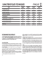
TYPE GM62N GM81N GL41N GL51N
CLASSE D'ISOLATION II II II II
TENSION DE TRAVAIL 230V-50Hz 230V-50Hz 230V-50Hz 230V-50Hz
COURANT ABSORBEE 9,7 A 9,7 A 5,8 A 5,8 A
PUISSANCE ABSORBEE 2.000 W 2.000 W 1.200 W 1.200 W
TOURS/MINUTE 6.000 8.000 4.000 5.500
DIAMETRE MAX. DE LA MEULE mm 230 178 230 178
FILETAGE ARBRE MANDRIN M 14 M 14 M 14 M 14
BLOCAGE ARBRE MANDRIN OUI NON NON NON
MASSE Kg 4,2 4,2 3,8 3,8
CARACTERISTIQUES TECHNIQUES FRANÇAIS 12

13
CONSIGNES DE SÉCURITÉ SPÉCIFIQUES AUX OPÉRATIONS DE MEULAGE ET
DE TRONÇONNAGE ABRASIF
Utilisez uniquement des meules recommandées pour votre outil et le protecteur
spécifique conçu pour la meule choisie. Les meules non conçues pour l’outil ne peuvent
pas être suffisamment protégées et présentent alors un danger.
Le protecteur doit être fermement fixé à l'outil et placé afin de garantir une sécurité
maximale, de sorte que l'opérateur soit exposé le moins possible à la meule. Le
protecteur permet de protéger l'opérateur contre les éventuels débris de la meule
endommagée et contre tout contact accidentel avec celle-ci.
Les meules ne doivent être utilisées que pour les applications préconisées. Par
exemple : ne meulez pas avec le côté de la meule à tronçonner. Les meules à
tronçonner abrasives étant destinées au meulage périphérique, l'application de forces
latérales à ces meules peut les briser.
Utilisez toujours des brides de serrage en parfait état, dont la taille et la forme sont
adaptées à la meule de votre choix. Les brides pour meule appropriées servent de
support à la meule et réduisent ainsi le risque de rupture de cette dernière.
Les brides pour les meules à tronçonner peuvent être différentes des autres brides de
meule. N’utilisez pas de meules usagées provenant d'outils de plus grande taille. Les
meules destinées à un outil de plus grande taille ne sont pas conçues pour les vitesses de
rotation plus élevées d’outils de plus petite taille et risquent de se casser.
Évitez de coincer la meule à tronçonner ou d’appliquer une pression excessive.
N’essayez pas d’effectuer de découpes trop profondes. Une forte pression sur la meule
augmente la charge et donc les risques de torsion ou de pliage de la meule dans la
découpe, ce qui entraînerait un rebond ou la rupture de la meule.
Ne vous placez pas dans l’axe de rotation de la meule, ni derrière celle-ci. Si la meule
au contact de la zone usinée s'éloigne de votre corps, le rebond éventuel peut propulser la
meule en rotation, ainsi que l'outil, directement dans votre direction.
Si la meule se plie ou si vous interrompez l’opération de coupe pour une raison
quelconque, mettez l'outil hors tension et évitez de le bouger jusqu’à l’arrêt complet de
la meule. N’essayez jamais de retirer la meule de la découpe lorsqu’elle est en mouvement
car elle risquerait de rebondir. Vérifiez les causes du pliage de la meule et prenez toutes les
mesures utiles afin que cela ne se produise plus.
Ne redémarrez pas l'opération de coupe avec la meule dans la pièce en cours
d’usinage. Attendez que la meule atteigne sa vitesse maximale puis introduisez-la
doucement dans la découpe. Si l'outil est redémarré alors que la meule se trouve dans la
pièce à usiner, la meule risque de se coincer, de sortir du matériau ou de rebondir.
Afin de réduire au minimum les risques de blocage ou de rebond de la meule,
prévoyez un support pour les panneaux ou pour toute pièce de grande dimension.
Les pièces de grande dimension ont tendance à plier sous l’effet de leur propre poids.
Les supports doivent être placés sous la pièce à usiner, près de la ligne de coupe et près du
bord de la pièce, des deux côtés de la meule.
Redoublez de prudence lorsque vous faites une « coupe en poche » dans des parois
existantes ou autres zones sans visibilité. La meule peut sectionner des canalisations de
gaz ou d'eau, des fils électriques ou des objets, ce qui peut entraîner des rebonds.
PARTIES DE LA MACHINE
1 - Étiquette d’identification
2 - Levier de l’interrupteur
3 - Verrouillage de l’interrupteur
4 - Bouton de blocage arbre mandrin (uniquement GM62N)
5 - Arbre mandrin
6 - Poignèe auxiliaire
7 - Protection orientable
8 - Collier pour fixation de la protection
9 - Ecarteur
10 - Collier de serrage
11 - Fentes pour ventilation moteur
12 - Clefs de service
MISE EN SERVICE
Avant de mettre la machine en service, s'assurer que:
- l'emballage est intégre et qu'il ne montre aucun signe d'endomma-
gements dus au transport et au stockage;
- la machine est complète; s'assurer que le nombre et la nature des composants sont
conformes aux indications contenues dans le présent livret d'instructions;
- la source d'énergie et les prises de courant à disposition peuvent supporter la charge indi-
quée dans le tableau et sur la plaquette d'identification de la machine, dont le fac-similé et
les explications relatives sont fournis page 15.
MONTAGE DE LA MACHINE
- Visser la poignèe auxiliaire (6) dans un des deux trous prèsents sur le carter renvoi d’an-
gle, elle peut être mise à droite ou à gauche du corps de la machine;
- monter la protection sur le corps de la machine à l’aide du collier (8) et la bloquer en ser-
rant la vis.
Le protection doit être montée au niveau de la poignée.
MONTAGE DES MEULES ABRASIVES
1. mettre l’ecanteur (9);
2. mettre le meule abrasive;
3. visser et serrer le collier de fixation (10) à l’aide de la clé à tétons en immobilisant l’arbre
mandrin à l’aide de la clé de 17 mm ou de le bouton de blocage arbre mandrin (unique-
ment GM62N).
AVANT LA MISE EN SERVICE
S'assurer que:
- la source d'énergie est conforme aux caractéristiques de la machine;
- le câble d'alimentation et la fische relative sont en parfait état;
- l'interrupteur de mise en marche/arrêt est efficace en agissant cependant lorsque la fiche
est débranchée;
- le bouton de blocage de l’arbre mandrin (4) est débranché (faire tourner à la main le meu-
le abrasive sur au moins un tour);
- tous les composants de la machine sont montès correctement et ne présentent pas de si-
gnes d'endommagement;
- les fentes de ventililation ne sont pas bouchées.
MISE EN MARCHE ET ARRET
- Mise en marche: pousser en avant le verrouillage de l’interrupteur (3) vers le corps de la
machine ; pousser au même moment le levier de l’interrupteur (2) vers le haut (fig. 4), de
cette façon l’interrupteur reste verrouillé en marche.
- Arrêt: pousser le levier de l’interrupteur (2) vers le haut de façon à libérer le verrouillage de
l’interrupteur (3).

14
FONCTIONNEMENT D'ESSAI
Mettre la machine en marche et s'assurer qu’il n’y a pas de vibrations anomales et que la
meule n'est pas décentré.
Dans le cas contraire, énteindie la machine immediatement et éliminer les anomalies.
DEMONTAGE ET REMPLACEMENT DES MUELES ABRASIVES
GM62N
Bloquer l'arbre porte-meule en poussant le bouton (4) et en faisant en même temps tourner
la meule jusqu'à ce qu'elle se bloque. Dévisser le collier à l'aide de la clé à tétons, remplacer
la meule, rivisser et serrer. Libérer l'arbre mandrin en relachant le bouton et faire tourner la
meule à la main pour s'assurer qu'elle s'est débloquée.
MISE EN GARDE!: ne jamais appuyer sur le bouton de blocage arbre mandrin avant
que l'outil ne soit completement arrete sous peine de rupture du boitier des engrena-
ges ou de la tige du bouton et de l'annulation de la garantie.
GM62N - GM81N - GL41N - GL51N
Pour bloquer l'arbre mandrin, introduire la clé de 17 mm dans l'encoche de l'arbre mandrin
entre la meule et la boitter des engranages. Devisser le collier a l’aide de la clé a tétons, rem-
placer la meule, rivisser et serrer.
Aucun autre outil n'est admis pour le serrage / desserrage.
OUTILS DE TRAVAIL ADMIS
GM81N - GL51N
Meules abrasives à centre dèprimè Ø 178 mm.
GM62N - GL41N
Meules abrasives à centre dèprimè Ø 230 mm.
ENTRETIEN
Toutes les opèrations doivent être effectuées à fiche ètant débranchèe.
A la fin du travail et en cas de nècessitè, dèpoussièrer le corps de la machine à l’aide d’un jet
d’air comprimè en faisant particuliérement attention au nettoyage des fentes de ventilation
du moteur.
Aucune autre intervention de l’utilisateur n’est pas admise.
Tous les travaux d’entretien et les travaux de polissage des piéces internes, comme les
brosses, coussinet, engrenages etc., doivent être effecuès par un atelier de réparation auto-
risè.
SECURITE ELECTRIQUE - BASSE TENSION
Les proves/verifies out eté executés en accord a les normes:
EN 60745-1 securité des outils électrique a moteur portatives
EN 60745-2-3 règles particuliers puor meuleuses.
PROTECTION CONTRE LES PARASITES RADIO
Les machines sont conformes à les effets de la prévention et des parasites radio mesures
en accord a les normes EN55014-1+EN55014-2; EN61000-3-2+EN61000-3-3.
FORMATION DU BRUIT
Le niveau de pression sonore, au poste de travail, généré par la machine en conditions nor-
males est de 88,7 dB (A) - puissance sonore 99,7 dB (A) - mesurés conformément aux nor-
mes EN ISO 3744 + UNI EN ISO 11202.
Attention: porter les dispositifs de protection de l'ouïe adéquats! (Cf. avertissements
généraux).
VALEUR MOYENNE DE L'ACCELERATION
La valeur quadratique moyenne de l'accèlération est inférieure à
2,5 m/sec
2
mesuré en accord a les normes UNI EN 28662 + UNI EN ISO 5349.
GARANTIE
Toutes les machines construites par la Société RUPES sont garanties pendant 12 mois à
compter de la date d’achat contre les défauts matériau et de fabrication.
Les machines ne doivent être utilisées qu'avec les pièces détachées et les accessoires ori-
ginaux RUPES: nous déclinons toute responsabilité en cas d'accidents ou de dégâts maté-
riels provoqués par le non-respect de cette norme, qui entraînera en outre l'annulation de la
garantie.
La garantie prend fin en cas de non-respect des prescriptions du présent livret ou en cas
d’utilisation impropre de la machine. Elle prend fin également si la machine est démontée
ou modifiée ou en cas de dommages évidents dérivant d’un mauvais entretien.
La garantie est subordonnée au remplissage du coupon qui se trouve à la dernière
page de couverture du présent livret d’instructions.
En cas de mauvais fonctionnement, la machine, accompagnée de son certificat de garan-
tie, devra être remise ou envoyée en port payé, non démontée et dans son emballage d’ori-
gine, au fabricant ou à un Centre d’Assistance agrée indiqué sur la liste annexée au présent
livret.
La garantie ne donne pas en aucun cas droit au remplacement de la machine.
RUPES se réserve le droit de modifier sans préavis les caractéristiques techniques ou
esthétiques des ses produits.
Nous déclinons toute responsabilité quant aux erreurs d'impression éventuelles. Ce docu-
ment annule et remplace tous les précédents.

15
IL PRESIDENTE
G. Valentini
DÉCLARATION DE CONFORMITÉ
Nous déclarons sous notre responsabilité que l’outil électrique à moteur portable, auquel se
réfère le présent manuel, est conforme aux Conditions Essentielles des Directives :
2006/42/CE Machines
2014/30/UE Compatibilité électrimagnétique
2011/65/UE RoHS
Les proves/vérifiés out été exécutés en accord a les vigueurs Régles Harmonisés
Européennes
EN ISO 12100: 2010 Sécurité des machines – Principes généraux de conception –
Appréciation du risque et réduction du risque
EN 60745-1: 2009 + A11:2010 Sécurité des outils électrique a moteur portatives
EN 60745-2-3: 2009 + A2:2013 + A11:2014 + A12:2014 + A13:2015 Règles particuliers
pour meuleuses, lustreuses et ponceuses a disque
Compatibilité électrimagnétique:
EN 55014-1:2006 + A1:2009 + A2:2011
EN 55014-2:1997 + A1:2001 + A2:2008
EN 61000-3-2:2014
EN 61000-3-3:2013
Directive RoHS:
EN IEC 63000:2018
PLAQUETTE D’IDENTIFICATION DE LA MACHINE
EMPLACEMENT ET SIGNIFICATION DES DONNEES
1. Type de la machine.
2. Tension nominale de travail en Volts (V).
3. Fréquence de travail en Hertz (Hz).
4. Courant absorbé exprimé en Ampéres (A). S’assurer que la ligne électrique à laquelle
la machine est branchée pourra aisément supporter au moins le courant indiqué.
5. Puissance absorbée exprimée en Watts (W).
6. Numéro d’immatriculation ou de série de la machine.
7. Caractéristiques techniques de la machine.
8. Nombre de tours/min.
9. Le double carré indique que la machine est à double isolement et que par consé-
quent, la mise à la terre par le cordon d’alimentation n’est pas nècessaire.
10. Lire toutes ces instructions avant de mettre en marche le présent produit.
11. Dispositifs de protection individuels.
12. Conformément à la Directive européenne 2002/96/CE (RAEE) + 2003/108/CE et à
sa mise en application dans la législation nationale, les vieux produits ne doivent être
jetés ni dans la nature ni avec les ordures ménagères mais être remis à un centre de
collecte sélective autorisé (adressez-vous à votre mairie pour savoir où vous débarras-
ser du produit conformément à la loi).L’élimination correcte du produit contribue à la
protection de la santé et de l’environnement. En n’éliminant pas le produit conformé-
ment à la loi en vigueur vous vous exposez à des sanctions.
S.p.A a socio unico
Vermezzo con Zelo (MI), 01/12/2021

16
ALLGEMEINE HINWEISE
Die Sicherheits- und Unfallverhütungsvorschriften sind im beiliegenden Heft
HINWEISE ZUR SICHERHEIT enthalten, das integrierender Teil dieser Dokumentation
ist. Diese GEBRAUCHSANLEITUNG enthält daher nur Zusatzinformationen, welche
den spezifischen Einsatz des Geräts betreffen.
BESTIMMNGSGEMÄßE VERWENDUNG
Dieses Werkzeug ist für den Einsatz als Schleifmaschine bestimmt. Alle
Sicherheitshinweise, die Anweisungen, die Abbildungen und die technischen Daten
beachten, die mit diesem Werkzeug geliefert werden. Die mangelnde Beachtung aller
unten aufgeführten Anweisungen kann zu elektrischen Schlägen, Brand und/oder schweren
Unfällen führen.
Von Vorgängen des Schleifens, metallischen Bürstens und Polierens mit diesem
Werkzeug wird abgeraten. Vorgänge, für die der Einsatz des Werkzeugs nicht vorgesehen
ist, können eine Gefahr darstellen und Personenschäden verursachen.
Kein Zubehör verwenden, das nicht ausdrücklich für den vorgesehenen Gebrauch
hergestellt oder vom Hersteller empfohlen wurde. Die bloße Tatsache, dass das Zubehör
auf Ihrem Werkzeug angebracht werden kann, garantiert keine Funktionsweise unter völlig
sicheren Bedingungen.
Die Nenngeschwindigkeit des Zubehörs muss mindestens der auf dem Werkzeug
angegebenen Höchstgeschwindigkeit entsprechen. Zubehör, dass bei einer
Geschwindigkeit über der Nenngeschwindigkeit verwendet wird, kann brechen und in die
Luft geschleudert werden.
Der Außendurchmesser und die Stärke Ihres Zubehörs müssen sich für den
Schutzgrad der Sicherheitsvorrichtung Ihres Werkzeugs eignen. Zubehör mit nicht
korrekten Größen kann nicht angemessen geschützt oder kontrolliert werden.
Die Beschaffenheit der Schleifscheiben oder jeglichen anderen Zubehörs muss sich
korrekt an das Spannfutter des Werkzeugs anpassen. Zubehör mit Bohrungen der
Welle, die nicht mit den Montageelementen auf dem Werkzeug übereinstimmen, bleiben ni-
cht im Gleichgewicht, vibrieren zu stark und können zu einem Kontrollverlust führen.
Verwenden Sie kein beschädigtes Zubehör. Vor jedem Einsatz das Zubehör wie die
Schleifscheiben auf eventuelle Splitterungen oder Risse untersuchen. Ist das
Werkzeug oder das Zubehör heruntergefallen, auf eventuelle Schäden untersuchen
oder nicht beschädigtes Zubehör installieren. Nachdem ein Zubehörartikel untersucht
und installiert wurde, begeben Sie sich gemeinsam mit den anwesenden Personen in
einen Sicherheitsabstand von dem rotierenden Zubehörartikel und lassen Sie das
Werkzeug bei Höchstgeschwindigkeit eine Minute lang leer laufen. Beschädigtes
Zubehör bricht im Allgemeinen während dieses Probezeitraums.
TYP GM62N GM81N GL41N GL51N
ISOLATIONSKLASSEIIIIIIII
SPANNUNG 230V-50Hz 230V-50Hz 230V-50Hz 230V-50Hz
STROMAUFNAHME 9,7 A 9,7 A 5,8 A 5,8 A
LEISTUNGSAUFNAHME 2.000 W 2.000 W 1.200 W 1.200 W
UMDREHUNGEN/MINUTE 6.000 8.000 4.000 5.500
MAX. SCHLEIF/TRENNSCHEIBEN-Ø mm
230 178 230 178
WELLENGEWINDE M 14 M 14 M 14 M 14
SPINDELARRETIERUNG JA NEIN NEIN NEIN
GEWICHT Kg 4,2 4,2 3,8 3,8
TECHNISCHE DATEN DEUTSCH 16

17
SPEZIFISCHE SICHERHEITSVORGÄNGE FÜR DIE VORGÄNGE DES SCHLEIFENS UND
ABRASIVSCHNEIDENS
Verwenden Sie ausschließlich die für Ihr Werkzeug empfohlenen Schleifscheibentypen und die
spezifisch für die gewählte Schleifscheibe ausgelegte Schutzvorrichtung. Schleifscheiben, für die
das Werkzeug nicht ausgelegt wurde, können nicht angemessen geschützt werden und sind daher
nicht sicher.
Die Schutzvorrichtung muss fest an dem Werkzeug angebracht und in die Position der
höchsten Sicherheit gebracht werden, damit der Benutzer so wenig wie möglich mit der
Schleifscheibe in Berührung kommen kann. Die Schutzvorrichtung sorgt für den Schutz des
Bedieners vor Bruchstücken der Schleifscheibe und dem versehentlichen Kontakt mit derselben.
Die Schleifscheiben dürfen nur für die empfohlenen Einsätze verwendet werden. Zum Beispiel:
nicht zum Schneiden mit der Seite der Schleifscheibe schleifen. Die zum Schneiden ausgelegten
Schleifscheiben dienen dem peripheren Schleifen und die Einwirkung seitlicher Kräfte kann diese
brechen lassen.
Stets unbeschädigte Schleifscheibenflansche verwenden, die die korrekte Größe und Form für
die gewählte Schleifscheibe aufweisen. Geeignete Schleifscheibenflansche stützen die
Schleifscheibe und verringern so die Möglichkeit des Brechens derselben.
Die Flansche für Schneidscheiben können von denen für Schleifscheiben abweichen. Keine mit
größeren Werkzeugen verwendeten Schleifscheiben verwenden. Die für ein größeres Werkzeug
bestimmte Schleifscheibe eignet sich wegen der höheren Drehzahlen eines kleineren Werkzeugs
nicht: die Schleifscheibe kann explodieren.
Die Schneidscheibe nicht “blockieren lassen” noch übermäßigen Druck ausüben. Nicht
versuchen, den Schnitt übermäßig tief auszuführen. Ein starker Druck auf der Schleifscheibe
erhöht die Last und die Wahrscheinlichkeit von Verziehungen oder Biegungen der Schleifscheibe im
Schnitt und die Möglichkeit von Rückschlägen oder des Brechens der Schleifscheibe.
Halten Sie sich nicht auf einer Linie mit der drehenden Schleifscheibe oder hinter dieser auf.
Wenn die Schleifscheibe sich während des Betriebs von Ihrem Körper entfernt, kann der eventuelle
Rückschlag die drehende Schleifscheibe zusammen mit dem Werkzeug direkt in Ihre Richtung
drücken.
Wird die Schleifscheibe gebogen oder der Schnitt wird aus einem beliebigen Grund
unterbrochen, das Werkzeug von der Stromversorgung trennen und ohne es zu bewegen
festhalten, bis dieses sich nicht mehr bewegt. Nie versuchen, die Schneidscheibe zu entfernen,
während diese sich bewegt, da dies zu Rückschlägen führen kann. Damit keine Biegungen der
Schleifscheibe mehr entstehen, müssen die Ursachen dafür gefunden und die entsprechenden
Korrekturmaßnahmen ergriffen werden.
Den Schneidvorgang im bearbeiteten Teil nicht wieder aufnehmen. Die Schleifscheibe ihre volle
Drehzahl erreichen lassen und dann vorsichtig den Schnitt wieder aufnehmen. Die
Schleifscheibe kann blockieren, sich nach oben bewegen oder einen Rückschlag erfahren, wenn das
Werkzeug im bearbeiteten Teil wieder gestartet wird.
Sehen Sie eine Abstützung für Platten oder jegliche anderen großen bearbeiteten Teile vor, um
das Risiko des Verklemmens und Rückschlags der Schleifscheibe auf ein Minimum zu
reduzieren. Große bearbeitete Teile neigen dazu, sich unter ihrem Eigengewicht zu biegen. Die
Abstützungen müssen auf beiden Seiten der Schleifscheibe in der Nähe der Schnittlinie und des
Rands des bearbeiteten Teils unter diesem positioniert werden.
Gehen Sie besonders vorsichtig vor, wenn sie einen “Taschenschnitt” in bestehenden Wänden
oder in anderen nicht einsehbaren Bereichen ausführen. Die hervorstehende Schleifscheibe kann
Gas- oder Wasserrohre, Elektrokabel oder Gegenstände erfassen, so dass Rückschläge möglich
sind.
BAUTEILE DER MASCHINE
1 - Schild mit Geräte-Kenndaten
2 - Hebel des Schalters
3 - Sperre des Schalters
4 - Spindel-Arretierknopf (nur GM62N)
5 - Spindel
6 - Seitenhandgriff
7 - Drehbarer Schutz
8 - Collare di fissaggio della protezione
9 - Abstandhalter
10 - Befestigungsring
11 - Motor-Lüftungsschlitze
12 - Service-Schlüssel
INBETRIEBNAHME
Vor einer Inbetriebnahme des Gerätes sollten Sie sicherstellen:
- daß die Verpackung unversehrt ist und keine Beschädigungen durch Transport bzw. Lagerung
aufweist;
- daß das Gerät vollständig ist, also Anzahl und Art der Gerätekomponenten mit den Angaben in die-
ser Gebrauchsanleitung überein stimmen;
-daß Stromnetz und Steckdosen für die in der Tabelle bzw. auf dem Geräteschild (vgl. Abbildung u.
Beschreibung des Gerateschilds auf Seite 19) genannte Stromlast ausgelegt sind.
ZUSAMMENBAU DER MASCHINE
- Den Seitenhandgriff (6) einschrauben, er kann wahlweise links, der Griff kann wahlweise an die linke
oder rechte Seite des Gerätegehäuses angesetzt werden;
-die Schutzabdeckung mit Hilfe des Kragens am Gerätegehäuse montieren und mit der Schraube
(8) fixieren.
Die Schutzhaube muß so montiert sein, daß sie den Bereich am Handgriff schützt.
BEFESTIGUNG VON SCHLEIF/TRENNSCHEIBE
1. Den Abstandhalter (9) einführen
2. die Trennscheibe aufsetzen;
3. die Spannmutter (10) aufschrauben und festziehen mit dem Inbusschlüssel, dazu die Spindel mit
dem 17 mm - Schlüssel kontern oder mit der Spindel-Arretierknopf (nur GM62N).
VOR DER INBETRIEBNAHME
Stellen Sie folgende Punkte sicher:
-das Stromntez entspricht den Gerätekenndaten;
- Anschlußkabel und-Stecker sind in ordnungsgemäßem Zustand;
- der EIN/AUS- Schalter funktioniert einwandfrei. Zur Überprüfung die in Kapitel “Inbetriebnahme” be-
schriebenen Schaltstellungen - allerdings bei gezogenem Netztstecker - ausprobieren;
-der Spindel-Arretierknopf (GM62N) (4) ist entriegelt (die Schleifscheibe manuell mindestens um eine
Umdrehung drehen);
-Sämtliche Gerätekomponenten sind ordnungsgemäß montiert und zeigen keine. Anzeichen von
Beschädigung;
- die Lüftungsschlitze sind nicht verstopft.
EINSCHALTEN UND AUSSCHALTEN
- Einschalten: Die Sperre des Schalters (3) nach vorn in Richtung des Maschinenkörpers stellen. Glei-
chzeitig den Hebel des Schalters (2) nach oben stellen (Abb. 4), so bleibt der Schalter auf der Funk-
tion blockiert.
- Ausschalten: den Hebel des Schalters (2) nach oben stellen, so dass die Sperre des Schalters (3)
gelöst wird.

18
TESTLAUF
Schalten Sie das Gerät ein und stellen Sie sicher, daß es nicht ungewöhnlich vibriert, order
die Trennscheibe berührt wird.
Andernfalls das Gerät sofort ausschalten und die Störung beheben.
ABNEHMEN UND ERSETZEN DER SCHLEIF/ TRENNSCHEIBEN
GM62N
Die Spanndornwelle blockieren. Hierzu die Taste (4) drücken und gleichzeitig die Schleif-
scheibe bis zum spürbaren Einrasten der Sperre drehen. Die Spannmutter mit denm In-
sbusschlüssel abschrauben und festizihen Danach die Spindel enntriegeln. Dazu den Ar-
retierkopf loslassen und die Scheibe von Hand durchdrehen, um zu prüfen, ob sie tatsächli-
ch entriegelt ist.
HINWEIS: der Spindel-Arretierknopf darf keinesfalls betätigt werden, bevor das Werk-
zeug nicht vollständig still steht, da sonst das Getriebegehäuse oder der stift des
Knopfes bricht, dies hat zudem ein erlöschen der Garantie zur folge.
GM62N - GM81N - GL41N - GL51N
Um die Spanndornwelle zu blockieren, den 17 mm-Schlüssel in die Kerbe der Welle zwi-
schen Schleifscheibe und Getriebekasten einführen.
Die Trennscheibe auswechseln und dann anschrauben und Festziehen.
Die Verwendung sonstiger Werkzeuge zum Festziehen/Lösen ist nicht zulässsig.
ZULÄSSIGE WERKZEUGE
GM81N - GL51N
Trennscheiben mit Ø 178 mm bzw.
GM62N - GL41N
Trennscheiben mit Ø 230 mm bzw.
PFLEGE DES GERÄTES
Sämtliche Eingriffe bei gezogenem Netzstecker ausführen.
Das Gerät nach der Arbeit sowie bei Bedarf mit Druckluft von Staub befreien. Besonders
darauf achten, daß die Lüftungsschlitze des
Motors sauber sind.
Sonstige Eingriffe durch den Geräteanwender sind nicht zulässig.
Für die Wartung und die periodische Reinigung von den inneren
Teilen z. B: Bürsten, Lagern, Zahnrädern usw. oder andere Bedürfnisse wenden Sie sich bit-
te an einer autorisierten Kundendienststelle an.
ELEKTRISCHE SICHERHEIT - NIEDERSPANNUNG
Die Tests wurden nach den Anforderungen der zur Zeit gültigen Normen ausgeführt:
EN 60745-1 sicherheit für tragbare elektrisch betriebe Maschinen
EN 60745-2-3 besondere Anforderungen für Winkelschleifer.
FUNKENTSTÖRUNG
Die Geräte erfüllen die Vorschriften der EG-Richtlinie 89/336 zur Vorbeugung und
Beseiti-gung von Funkstörungen Messung nach Norm EN55014-1+EN55014-2;
EN61000-3-2+EN61000-3-3.
SCHALLPEGEL
Der von der Maschine unter normalen Betriebsbedingungen am Arbeitsplatz
verursachte Schalldruckpegel entspricht 88,7 dB (A) - Schalleistung 99,7 dB (A) -
gemessen gemäß EN ISO 3744 + UNI EN ISO 11202.
Achtung: Während des Betriebs angemessenen Gehörschutz tragen! (siehe
allgemei-ne Hinweise)
MITTLERE BESCHLEUNIGUNG
Die mittlere quadratische Beschleunigung liegt unter 2,5 m/s
2
Messung nach UNI
EN 28662+ UNI EN ISO 5349.
GARANTIE
Für alle von ihr hergestellten Geräte leistet die Fa. RUPES Gewähr im von
Mangeln, die innerhalb von 12 Monaten ab dem Kaufdatum aufgrund Material-
oder Fabrikationsfehlern auftreten.
Die Maschinen dürfen ausschließlich mit Originalzubehör und Originalersatzteilen
von RU-PES betrieben werden: Das Unternehmen haftet nicht für Unfälle oder
Schäden, die auf die Nichtbeachtung dieser Bestimmung zurückzuführen sind,
die außerdem zum unverzügli-chen Verfall der Garantie führt.
Der Garantieanspruch entfällt bei unsachgemäßem Gebrauch des Gerätes oder
der Nich-teinhaltung dieser Gebrauchasanleitung.
Er entfällt ebenfalls, wenn das Gerät demontiert bzw. umgerüstet wurde oder
sichtbare Schäden infolge mangelhafter Pflege aufweist.
Die Inansprunchnahme der Garantieleistung ist nur möglich, wenn der
Abschnitt auf der vorletzten Umschlagseite dieser Gebrauchsanleitung
ausgefüllt ist.
Im Fall einer nachweislichen Funktiosstörung muß das Gerät dem Hersteller
komplett mon-tiert, originalverpackt und mit beiliegender Garantiekarte fracht und
portofrei übergeben bzw. zugesendet werden. Die Übergabe an ein autorisiertes
Kundendienstzentrum (siehe beiliegendes Verzeichnis) ist ebenfalls möglich. In
keinem Fall leitet sich aus dem Garantieanspruch ein Rechtsanspruch auf die
Ersetzung des Gerätes ab.
Die Fa. RUPES behält sich das Recht vor, ohne Vorankündigung technische und
ästhetische Änderungen an ihren Produkten vorzunehmen.
Das Unternehmen haftet nicht für eventuelle Druckfehler. Vorliegendes Dokument
annulliert und ersetzt alle früheren Veröffentlichungen.

19
KENNDATENSCHILD DES GERÄTES
ANORDNUNG UND BEDEUTUNG DER ANGABEN
1. Gerätetyp.
2. Nenn-Anschlußspannung in Volt (V).
3. Frequenz in Hertz (Hz).
4. Stromaufnahme in Ampere (A).Es ist sicherzustellen, daß die Stromleitung, an die das
Gerät angeschlossen werden soll, mindestens diese Strombelastung problemlos au-
shält.
5. Leistungsaufnahme in Watt (W).
6. Geräte- oder Seriennummer.
7. Technische Gerätedaten.
8. Drehzahl in Umdrehungen/Min.
9. Das doppelte Quadrat zeigt an, daß das Gerät zweifach schutzisoliert ist und daher kei-
ne Erdung über das Anschlußkabel erforderlich ist.
10. Lesen Sie diese Hinweise aufmerksam durch, bevor Sie das vorliegende Produkt in
Betrieb nehmen.
11. Persönliche Schutz-Ausrüstung.
12. Das Produkt darf entsprechend der Europäischen Richtlinie 2002/96/CE (RAEE) +
2003/108/CE und deren Umsetzung in der nationalen Gesetzgebung am Ende seiner
Lebensdauer nicht weggeworfen oder im Hausmüll entsorgt werden, sondern muss
bei den autorisierten Zentren zur Abfalltrennung abgegeben werden (wenden Sie sich
an die zuständigen Behörden vor Ort, um zu erfahren, wo das Produkt nach den ge-
setzlichen Bestimmungen zu entsorgen ist). Die korrekte Entsorgung des Produkts
trägt zum Schutz der Gesundheit und der Umwelt bei. Die missbräuchliche Entsorgung
des Produkts zieht Sanktionen zu Lasten des Verursachers nach sich.
IL PRESIDENTE
G. Valentini
KONFORMITÄTSERKLÄRUNG
Wir bestätigen in unserer Verantwortung das die Handgehaltenen Motorwerkzeuge, die in
diesem Betriebshandbuch beschrieben werden, ist in Übereinstimmung mit den wesentli-
chen Bestimmungen für die Sicherheit der folgenden Direktiven:
2006/42/CE Maschinenrichtlinie
2014/30/EU Elektromagnetische Verträg
2011/65/EU RoHS
Die Tests wurden ausgeführt nach den Anforderungen der zur Zeit gültigen europäischen
Harmonisierungsregeln Niederspannung:
EN ISO 12100: 2010 Sicherheit von Maschinen – Allgemeine Gestaltungsleitsätze –
Risikobeurteilung und Risikominderung
EN 60745-1: 2009 + A11:2010 Sicherheit für tragbare elektrisch betriebene Maschinen
EN 60745-2-3: 2009 + A2:2013 + A11:2014 + A12:2014 + A13:2015 Besondere
Anforderungen für Winkelschleifer, Poliermaschinen und Schleifmaschinen mit
Scheibe
Elektromagnetische Verträglichkeit:
EN 55014-1:2006 + A1:2009 + A2:2011
EN 55014-2:1997 + A1:2001 + A2:2008
EN 61000-3-2:2014
EN 61000-3-3:2013
RoHS-Richtlinie:
EN IEC 63000:2018
S.p.A a socio unico
Vermezzo con Zelo (MI), 01/12/2021

20
ADVERTENCIAS GENERALES
Las instrucciones para la seguridad y la prevención de los accidentes se
encuentran en el folleto INDICACIONES PARA LA SEGURIDAD que constituye
parte integrante de esta documentación. Este MANUAL DE INSTRUCCIONES
de uso contiene solamente información adicional estrechamente relacionada
con el uso específico de la máquina.
USO CONFORME A LO DETERMINADO
Esta herramienta está destinada a funcionar como esmeriladora. Leer todas
las advertencias de seguridad, las instrucciones, las ilustraciones y las espe-
cificaciones suministradas con esta herramienta. El incumplimiento de las in-
strucciones puede causar descargas eléctricas, incendios y/o accidentes graves.
Se recomienda no ejecutar con esta herramienta operaciones de lijado, ace-
pilladura metálica ni pulido. El empleo de la herramienta eléctrica en operaciones
para las que no está diseñada puede provocar peligros y daños a las personas.
No utilizar accesorios no realizados específicamente para el uso previsto o no
aconsejados por el productor. El hecho de que el accesorio se pueda fijar en la
herramienta no garantiza un funcionamiento totalmente seguro.
La velocidad nominal del accesorio debe ser al menos igual a la velocidad
máxima indicada en la herramienta. Los accesorios que se hagan funcionar a
una velocidad superior a la nominal pueden romperse y saltar por el aire.
El diámetro exterior y el espesor de su accesorio deben responder a las ca-
racterísticas de capacidad de la protección de seguridad de su herramienta
eléctrica. Los accesorios de dimensiones no correctas no se pueden proteger y
controlar adecuadamente.
La conformación de las muelas o de cualquier otro accesorio debe adaptarse
correctamente al mandril de la herramienta. Los accesorios cuyos orificios en el
eje no correspondan con los elementos de montaje en la herramienta no permane-
cerán en equilibrio, vibrarán excesivamente y podrán provocar una pérdida de con-
trol.
No utilizar accesorios dañados. Antes del uso, examinar los accesorios, como
las muelas abrasivas, para asegurarse de que no presentan mellas o grietas.
Si la herramienta o el accesorio han sufrido una caída, verificar si hay daños o
instalar un accesorio no dañado. Una vez examinado e instalado un accesorio,
colocarse a una distancia de seguridad del accesorio giratorio, al igual que
las demás personas presentes, y poner en funcionamiento la herramienta a la
velocidad máxima en vacío durante un minuto. Los accesorios dañados general-
mente se rompen durante el período de prueba.
TIPO GM62N GM81N GL41N GL51N
CLASE DE AISLAMIENTO II II II II
TENSION DE OPERACION 230V-50Hz 230V-50Hz 230V-50Hz 230V-50Hz
CORRIENTE ABSORBIDA 9,7 A 9,7 A 5,8 A 5,8 A
POTENCIA ABSORBIDA 2.000 W 2.000 W 1.200 W 1.200 W
REVOLUCIONES POR MINUTO 6.000 8.000 4.000 5.500
DIAMETRO MAX. DE LA MUELA mm 230 178 230 178
ROSCADO ARBOL MANDRIL M 14 M 14 M 14 M 14
TOPE ARBOL
MANDRIL SINONONO
MASA Kg 4,2 4,2 3,8 3,8
DATOS TECNICOS ESPAÑOL 20
La page est en cours de chargement...
La page est en cours de chargement...
La page est en cours de chargement...
La page est en cours de chargement...
La page est en cours de chargement...
La page est en cours de chargement...
La page est en cours de chargement...
La page est en cours de chargement...
La page est en cours de chargement...
La page est en cours de chargement...
La page est en cours de chargement...
La page est en cours de chargement...
-
 1
1
-
 2
2
-
 3
3
-
 4
4
-
 5
5
-
 6
6
-
 7
7
-
 8
8
-
 9
9
-
 10
10
-
 11
11
-
 12
12
-
 13
13
-
 14
14
-
 15
15
-
 16
16
-
 17
17
-
 18
18
-
 19
19
-
 20
20
-
 21
21
-
 22
22
-
 23
23
-
 24
24
-
 25
25
-
 26
26
-
 27
27
-
 28
28
-
 29
29
-
 30
30
-
 31
31
-
 32
32


Rupes GM62N Angular Grinders Manuel utilisateur
- Taper
- Manuel utilisateur
dans d''autres langues
Documents connexes
Autres documents
-
Hitachi G 18SS Le manuel du propriétaire
-
-
Sparky Group M 600 Manuel utilisateur
-
Hitachi G10SR3 Le manuel du propriétaire
-
Hitachi G 13V Manuel utilisateur
-
Hitachi G 23SR Le manuel du propriétaire
-
Milwaukee WCE 65 Original Instructions Manual
-
Hitachi G 12SA3 Le manuel du propriétaire
-
Ferm AGM1041 Le manuel du propriétaire
-
Hitachi G 13SD Manuel utilisateur