Pleasant Hearth HWS-224172MH Series Le manuel du propriétaire
- Catégorie
- Poêles
- Taper
- Le manuel du propriétaire
Ce manuel convient également à

60-10-001
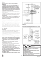
Warming Your Home. Warming Your Heart. raW imr gni oY ruo H emo e aW mra gni Yg ruoY Hr aeH tr raW imr gni oY ruo H emo .e aW mra gni Yg ruoY Hr aeH .tr
8280 Austin Avenue
Morton Grove, IL 60053
877-447-4768
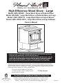
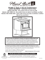
High Efficiency Wood Stove - Large
Model: HWS-230292 - Large Wood Stove w/Pedestal Base
Model: WS-3029 - Large Wood Stove w/Pedestal Base and Legs
Model: LWS-130291-B - Large Wood Stove w/Legs & Blower
Model: LWS-130291-BCA - Large Wood Stove w/Legs & Blower
Owner’s Manual
Questions, problems, missing parts? Before returning to your retailer, call our
customer service department at 877-447-4768 8:30 a.m. - 4:30 p.m. CST,
Monday - Friday or e-mail us at [email protected].
SAFETY NOTICE: IF THIS WOOD BURNING APPLIANCE IS NOT PROPERLY INSTALLED,
OPERATED, AND MAINTAINED, A HOUSE FIRE MAY RESULT.
TO REDUCE THE RISK OF FIRE, FOLLOW THE INSTALLATION INSTRUCTIONS. FAILURE
TO FOLLOW THE INSTALLATION INSTRUCTIONS MAY RESULT IN PROPERTY DAMAGE,
BODILY INJURY OR EVEN DEATH. CONTACT LOCAL BUILDING OFFICIALS ABOUT
RESTRICTIONS AND INSTALLATION INSPECTION REQUIREMENTS IN YOUR AREA.
This manual describes the installation and operation of the Model HWS-230292, Model WS-3029,
and Model LWS-130291 non-catalytic wood heater. This heater meets US Environmental Protection
Agency’s emission limits for wood heaters. Under specific conditions this heater has been shown to
deliver heat at rates ranging from 12,000 to 35,000 BTU/hr.
This stove is listed by OMNI-Test Laboratories
of Portland, Oregon to meet UL1482 for the US
and ULC-S627 for Canada.
6” Flue required
Do Not Discard This Manual: Retain for Future Use

60-10-001
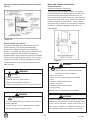
('"!
A
fter reading these instructions, if you have any doubt
about your ability to complete your installation in a pro-
fessional like manner you should obtain the services of
an installer versed in all aspects as to the correct and
safe installation. Do not use temporary makeshift com-
promises during installation.
"%!&''"!"+"(%##!
1. Check with the building inspector's office for compli-
ance with local codes; a permit may be required.
2. The room heater must be connected to 1) a chimney
complying with the requirements for Type HT chimneys in
the standard for Chimneys, Factory-Built, Residential
Type and Building Heating Appliance, UL 103, or in
Canada ULC S627 Standard for 650 degree C Factory
Built Chimneys and applicable building codes or 2) a
code-approved masonry chimney with a flue liner.
3. A 6" (152mm) diameter, 24 gauge Black Steel flue is
required for proper performance.
4. Always connect this unit to a chimney and NEVER
vent to another room or inside a building.
5. DO NOT connect this unit to any duct work to which
another appliance is connected such as a furnace.
6. "!"'"!!''&(!''" !+
(&%)!!"'%##!
7. The connector pipe and chimney should be inspected
periodically and cleaned if necessary.
8. Remember the clearance distances when you place
furniture or other objects within the area. "!"' store
wood, flammable liquids or other combustible materials
too close to the unit.
%121=?:/1=?525/-?5:97-.17:9.-/6:2D:@=@95?2:=
=1<@5=10/71-=-9/1>
9. Contact your local municipal or provincial fire authori-
ty for information on how to handle a chimney fire. Have
a clearly understood plan to handle a chimney fire. In the
event of a Chimney fire, turn air control to closed position
and '%#%' !'.
10. "!"' tamper with combustion air control beyond
normal adjustment.
11. "!"' !&''&(!'&! "
" "%'%%'&(!'&%!"'
"" ##%")
12. "!"'"!!''"!+%&'%('"!
('"%&+&'
"#%'"!
*+'"%%'(&,& #"%'!'
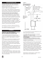
Draft is the force which moves air from the appliance up
through the chimney. The amount of draft in your chimney
depends on the length of the chimney, local geography,
n
earby obstructions, and other factors. Too much draft may
cause excessive temperatures in the appliance. An uncon-
trolled burn or a glowing red part or chimney connector
indicates excessive draft. Inadequate draft may cause
back puffing into the room and "plugging" of the chimney
and/or cause the appliance to leak smoke into the room
through appliance and chimney connector joints.
T
oday's solid fuel appliances are more efficient than in the
past. The units are designed to give you controlled com-
bustion, and maximum heat transfer, using less fuel to do so.
The design of your new appliance is such that the exhaust
smoke is now at lower temperatures than in the past,
therefore requiring proper chimney size to give adequate
draft. If your chimney is too large, the heating appliance
will have a difficult time to raise the chimney flue temper-
ature to give adequate draft, therefore causing a smoke
back up, poor burn, or both.
&4:@70D:@1C;1=519/1>@/4-;=:.718/-7759-7:/-7
/45891D1C;1=?
With the door closed, the rate of burning is regulated by
the amount of air allowed to enter the unit through the air
control. With experience you will be able to set the con-
trol for heat and burning time desired.
Once the required chimney draft is obtained, operate only
with doors closed and open doors slowly when re-fueling.
(This will reduce or eliminate smoke from entering the room).
Attempts to achieve higher output rates that exceed
heater design specifications can result in permanent
damage to the heater. The recommended wood load is
level with the top of the firebricks.
Overloading may prevent sufficient air entering the heater
to properly fuel the fire.
Operate this heater only with the door closed.
"!"'(%!%"% (&
&(&&"!!#'"%!!"
"!"'(& &"%(&'"&'%'
'%
ALWAYS PROVIDE A SOURCE OF FRESH AIR INTO
THE ROOM WHERE THE UNIT IS INSTALLED. FAIL-
URE TO DO SO MAY RESULT IN AIR STARVATION OF
OTHER FUEL BURNING APPLIANCES AND THE POS-
SIBLE DEVELOPMENT OF HAZARDOUS CONDITIONS.
HOT WHILE IN OPERATION. KEEP CHILDREN,
CLOTHING AND FURNITURE AWAY. CONTACT MAY
CAUSE SKIN BURNS.
OPTIONAL BLOWER: MODEL PBAR-2427,
120 VOLTS, 60Hz, 0.75 AMPS, 2900 RPM
DANGER: RISK OF ELECTRIC SHOCK.
DISCONNECT POWER BEFORE SERVICING UNIT.
IMPORTANT: FOR OPTIMUM HEATER
PERFORMANCE AT LOW BURN RATE, OPERATE
THE FAN AT LOW SPEED.

60-10-001
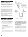
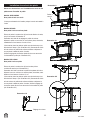
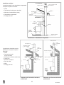
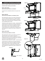
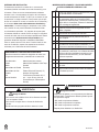
#101>?-7->1-90139>?-77-?5:9
12:=19>?-77593&?:A1:77:B'41>1 &?1;>2:=
#
101>?-7->1-907139>?-77-?5:9
:017*&
-=31*::0&?:A1B#101>?-7->1
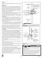
Pedestal base is pre-installed at the factory. No action is
required.
:017*&
-=31*::0&?:A1B#101>?-7->1-9013>
Remove Ash pan and (4) bolts that secure the stove body
to the pedestal as shown in Figure 0.
With assistance, lift stove off of pedestal and lay stove
on its side on a safe, elevated, padded and level platform
that is about 6” off the ground.
Using the bolts that were removed in step 1, bolt each
leg to the bottom of the stove as shown in Figure 0.2.
With assistance, lift the stove off of the raised platform,
set upright on the legs, and re-install the ash pan.
When stove is in place for installation, make sure stove is
level by adjusting the leg levelers shown in Figure 0.3.
:017*&
-=31*::0&?:A1B13>
Remove ash pan and (4) bolts in angle iron bracket as
shown in Figure 0.1.
With assistance, lift stove off of wooden pallet and lay
stove on its side on a safe, elevated, padded and level
platform that is about 6” off the ground.
Using the bolts that were removed in step 1, bolt each
leg to the bottom of the stove as shown in Figure 0.2.
With assistance, lift the stove off of the raised platform,
set upright on the legs and re-install the ash pan.
When stove is in place for installation, make sure stove is
level by adjusting the leg levelers shown in Figure 0.3.
53@=1
53@=1
53@=1
53@=1
leg leveler
ash pan

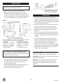
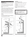
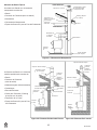
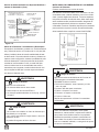
!&''"!
1
. Remove all parts from inside the stove body.
2. Select the proper location for the stove. These
appliances must not be installed any closer than the
m
inimum clearance to combustible materials shown
in Brick pattern (Figure 1). The stove must be installed
on a non combustible surface as shown in Figure 1.
3. If noncombustible materials have been installed on
the walls, obtain the minimum clearances from either
the manufacturer of these materials or the local
building inspectors office.
4. Install the stovepipe INSIDE the flue collar on the top
of the stove between the stove and chimney.
5. DO NOT use a grate to elevate the fire.
60-10-001
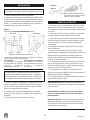
&'")##
1. A clearance of 18 inches (457mm) between the
stovepipe and combustible materials may be required.
Check with authorities having jurisdiction in your area.
2. All pipe sections must be connected with the male end
(crimped end) toward the stove.
3. Fasten the stove pipe to the flue collar by the use of
three sheet metal screws. Do the same at each
additional joint to make the entire installation rigid.
4. Maintain the required diameter flue for the entire
installation.
5. If you are connecting the stove to an old masonry flue,
be sure to have it inspected for cracks and general
condition. Resizing with a stainless steel liner may be
required.
6. It is recommended that no more than two (2) 90°
bends be used in the stove pipe installation. More
than two (2) 90° bends may decrease the amount
of draw and possibly cause smoke spillage.
7. A damper is not required in this installation. Remove
damper plate in the chimney or secure in OPEN position.
8. Single wall flue pipe assemblies must not exceed
10 feet (3 m) in overall length.
('"!"!"'open fire-door to a point where it
would be in contact with the combustible sidewall.
('"! Brick for ash drawer must be installed before
operation of wood heater.
";?5:9-7-9 - An optional heat exchange blower is
available for this wood burning appliance. To order
please see the local dealer where you purchsed the
appliance.
Contact your local building inspector prior to installation.
A permit may be required in your area.
Unit must be placed on a noncombustible floor protec-
tion equivalent to 1” millboard. Floor protector must
have min. R value of .893. Consult your local building
authorities for further information.
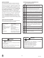
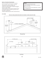
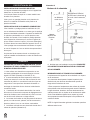
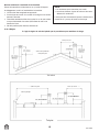
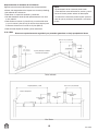
A minimum clearance of 18” (457 mm) to the chimney connector
may be required by the authority having jurisdiction.
From Heater From Chimney Connector
A. Sidewall 22” (559 mm) D. Sidewall 32” (813 mm)
B. Back Wall 16” (406 mm) E. Back Wall 19” (483 mm)
C. Corner 12” (305 mm) F. Corner 21.5” (546 mm)
Minimum height to ceiling 55” (1397 mm)
*16” (406 mm) US **18” (457 mm) Canada
53@=1
53@=1

60-10-001
""%#%"''"!
!&''"!"!"!%'""%
An appliance mounted on a concrete floor does not
require floor protection.
Carpeting and any other combustible material shall not
cover Floor Protector.
If a combustible surface is applied to the concrete
floor, a clearance must be maintained equivalent to
the area reserved for the floor protector.
!&''"!"!" (&'""%
If the appliance is to be installed on a combustible floor
or a combustible floor covering, it must be installed on
a 1” (26 mm) thick, non-combustible millboard floor
protector or durable equivalent. The pad must be
installed beneath the appliance extending past the
glass 18” (457 mm) in Canada, 16” (406 mm) in the
U.S. On any side equipped with a door, and 8”
(203 mm) on all other sides. In the U.S. the pad must
cover any horizontal chimney connector runs and extend
2” (51 mm) beyond each side.
A grouted ceramic floor-tile surface installed per local
building code is considered a durable equivalent.
!+
"!''+"(%"(!('"%'+
"%##%") '"&"!&''"!
1. This appliance requires a masonry or pre-manufactured
chimney listed to ULC S627 (Canada) and UL103HT
(USA) sized correctly.
2. If a masonry chimney is used it is advisable to have
your chimney inspected for cracks and check the
general condition before you install your unit.
Relining may be required to reduce flue diameter to
the appropriate functional size.
3. To help ensure a good draft, the top of the chimney
should be at least 3 feet (914mm) above the point of
penetration through the roof, and be at least 2
(610mm) feet higher than any point of the roof within
10 feet (3M).
4. The chimney connector shall not pass through an
attic, roof space, closet, concealed space, floor,
ceiling, wall, or any partition of combustible construction.
5. The minimum overall height of your chimney should be
15 feet (5 m) from the floor (Figure 3).
6. Do not use makeshift compromises during installation.
%%'" !+ !('(%%H&!&'%('"!&
(%'"!&%'"!&
Location of the appliance and chimney will affect per-
formance. The chimney should:
• Penetrate the highest part of the roof. This minimizes
the affects of wind turbulence and down drafts.
• Consider the appliance location in order to avoid floor
and ceiling attic joists and rafters.
Exterior conditions such as roof line, surrounding trees,
prevailing winds and nearby hills can influence stove per-
formance. Your local dealer is the expert in your geo-
graphic area and can usually make suggestions or dis-
cover solutions that will easily correct your flue problem.
NOTE: These are guidelines only, and may vary some-
what for individual installations.
53@=1

60-10-001
!&#'##!" #"!!'&!
#%(&&'
1
. Place the appliance in a location near the final
installation area and follow the procedures below:
2. Open the appliance and remove all the parts and
articles packed inside the Component Pack.
Inspect all the parts and glass for shipping damage.
Contact your dealer if any irregularities are noticed.
3. All safety warnings have been read and followed.
4. This Owner’s Manual has been read.
5. Floor protection requirements have been met.
6. Venting is properly installed.
7. The proper clearances from the appliance and
chimney to combustible materials have been met.
8. The masonry chimney is inspected by a professional
and is clean, or the factory built metal chimney is
installed according to manufacturer’s instructions
and clearances.
9. The chimney meets the required minimum height.
10. All labels have been removed from the glass door.
11. A power outlet is available nearby if installing
optional blower assembly.
)!'!&+&' &
The venting system consists of a chimney connector
(also known as stove pipe) and a chimney. These get
e
xtremely hot during use. Temperatures inside the chim-
ney may exceed 2000°F (1100°C) in the event of a cre-
osote fire. To protect against the possibility of a house
fire, the chimney connector and chimney 8@>?.1;=:;
1=7D59>?-7710-908-59?-5910 An approved thimble
must be used when a connection is made through a
combustible wall to a chimney. A chimney support pack-
age must be used when a connection is made through
the ceiling to a prefabricated chimney. These acces-
sories are -.>:7@?17D91/1>>-=D to provide safe clear-
ances to combustible wall and ceiling material. Follow
venting manufacturer’s clearances when installing venting
system.
'""&!&(##&!
Before beginning the installation be sure that the follow-
ing tools and building supplies are available.
Reciprocating saw Framing Material
Pliers Hi-Temp Caulking Material
Hammer Gloves
Phillips Head Screwdriver Framing Square
Flat Blade Screwdriver Electric Drill & Bits (1/4”)
Plumb Line Safety Glasses
Level 1/2 in. - /4 in. length, #6 or
Tape Measure #8 self drilling screws (need
per pipe section connection)
*%!!
>;4DC5-?5:9%5>6
• Do NOT connect this unit to a chimney flue servicing
another appliance.
• Do NOT connect to any air distributon duct or system.
May allow flue gases to enter the house.
*%!!
5=1%5>6
Inspect appliance and components for damage.
Damaged parts may impair safe operation.
• Do NOT install damaged components.
• Do NOT install incomplete components.
• Do NOT install substitute components.
Report damaged parts to dealer.

60-10-001
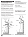
'D;5/-7&?:A1&D>?18>
Stove system with masonry chimney
consists of:
• Stove
•
Chimney Connector (stove pipe)
• Thimble
• Masonry Chimney
• Hearth Pad Floor Protection
Stove system with prefabricated
metal chimney consists of:
• Stove
• Chimney Connector (stove pipe)
• Thimble (for exterior chimney)
• Firestops
• Insulations Shields
• Storm Collar and Flashing
• Termination Cap
• Hearth Pad Floor Protection
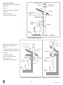
53@=1 ->:9=D45891D
53@=1C?1=5:=#=12-.=5/-?1045891D 53@=19?1=5:=#=12-.45891D

60-10-001
!+&+&' &
#=12-.=5/-?10 1?-745891D
• Must be a 6 inch (152mm) diameter (ID) high tempera-
t
ure chimney listed to UL 103HT (2100°F) or ULC S627.
• Must use components required by the manufacturer for
installation.
• Must maintain clearances required by the manufacturer
for installation.
• Refer to manufacturers instructions for installation.
!"' In Canada when using a factory-built chimney
it must be safety listed, 'D;1('E
&&FG or conforming to !(&
&'!%"%E'"%+(' !+&
!+%$(% !'&
)
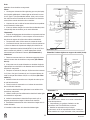
!'!" #"!!'&
45891D:991/?:=
I
t is also known as flue pipe or stove pipe. The chimney
connector joins the stove to the chimney. It must be a 6
inch (152mm) minimum diameter 24 gauge mild steel
black steel, or an approved air-insulated double wall
venting pipe.
'458.71
A manufactured or site-constructed device installed in
combustible walls through which the chimney connector
passes to the chimney. It is intended to keep the walls
from igniting. Site constructed thimbles must meet NFPA
211 Standards. Prefabricated must be suitable for use
with selected chimney and meet UL103 Type HT
Standards. Follow instructions provided by the manufac-
turer for manufactured thimbles for masonry chimney and
prefabricated chimneys.
45891D
The chimney can be new or existing, masonry or prefab-
ricated and must meet the following minimum require-
ments specified in Section 5B.B.
53@=1#=12-.=5/-?10C?1=5:=45891D 53@=1#=12-.=5/-?109?1=5:=45891D

60-10-001
'458.71
S
ite constructed for masonry chimney installation:
:8;:919?>
• A minimum length of 12 inches [05mm] (longer for
thicker walls) of solid insulated factory-built chimney
length constructed to UL 103 Type HT 6 inch (152mm)
inside diameter. Chimney needs to extend a minimum of
2
inches (51mm) from the interior wall and a minimum of
1 inch (25mm) from the exterior wall.
• Wall spacer, trim collar and wall band to fit solid pack
chimney selected.
• Minimum 8 inch (20mm) diameter clay liner section (if
not already present in chimney) and refractory mortar.
5=71-=-9/1>
• Masonry chimney clearance must meet NFPA 211 min-
imum requirement of 2 inches (51mm) to sheet metal
supports and combustibles.
• Minimum of 1 inch (25mm) clearance around the chim-
ney connector.
• Top of wall opening is a minimum of 1-1/2 inches
(4mm) from ceiling or 4-1/2 inches (114mm) below mini-
mum clearance specified by chimney connector manu-
facturer. NFPA 211 minimum vertical clearance of 18
inches (457mm) from chimney connector and ceiling or
minimum recommended by chimney connector manufac-
turer. 53@=1
9>?=@/?5:9>
1. Open inside wall at proper height for the chimney con-
nector to entry the masonry chimney. 53@=1
2. Entry hole to masonry chimney must be lined with an 8
inch (20mm) minimum diameter clay liner, or equiva-lent,
secured with refractory mortar.
3. Construct a 17 inch x 17 inch (42mm x 42mm) out-
side dimension frame from 2 x 2 framing lumber to fit
into wall opening. Inside opening of frame should be no
less than 14 inch x 14 inch (56mm x 56mm). 53@=1
4. Attach the wall spacer to the chimney side of the
frame.
5. Nail the frame into the wall opening. The spacer
should be on the chimney side.
6. Insert the section of the solid insulated chimney into
the outer wall of the masonry chimney.
7. Tightly secure the length of the solid insulated chimney
with the wall band to the masonry chimney.
8. Insert a section of chimney connector into the chim-
ney. Make sure it does not protrude past the edge of the
clay chimney liner inside the chimney.
9. Seal the end of the chimney connector to the clay liner
with refractory mortar.
10. Install trim collar around the sold pack chimney section.
53@=1
&:750#-/645891DB5?4 1?-7&@;;:=?>->-'458.71
53@=1
*%!!
5=1%5>6
Do NOT pack insulation or other combustibles
between spacers.
• ALWAYS maintain specified clearances around
venting and spacers.
• Install spacers as specified.
Failure to keep insulation or other material away
from vent pipe may cause fire.

60-10-001
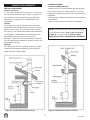
&:750#-/645891DB5?4 1?-7&@;;:=?>->-'458.71
:9?H0
45891D1534?%5>1-90%@9
This product was designed for and tested on a 6 inch
(152mm) chimney, 14 to 16 feet (420-480cm) high,
(includes stove height) measured from the base of the
appliance. The further your stack height or diameter varies
from this configuration, the possibility of performance
problems exists. Chimney height may need to be increased
by 2% per each 1000 feet above sea level. It is not recom-
mended to use offsets or elbows at altitudes above 4000
feet above sea level or when there are other factors that
affect flue draft.
!&'! !+" #"!!'&
45891D:991/?:=
Single wall connector or stove pipe.
T
his must be at least 24 gauge mild steel. The sections
must be attached to the appliance and to each other with
the crimped (male) end pointing toward the stove. All
joints, including the connection at the flue collar, should be
secured with sheet metal screws. Make sure to follow the
minimum clearances to combustibles. Where passage
through the wall, or partition of combustible construction
is desired in Canada, the installation shall conform to
CAN/CSA-B65.
53@=1
53@=1
*%!!
>;4DC5-?5:9%5>6
• Do NOT connect this unit to a chimney flue servicing
another appliance.
• Do NOT connect to any air distributon duct or system.
May allow flue gases to enter the house.
*%!!
Improper installation, adjustment, alteration, service or
maintenance can cause injury or property damage. Refer
to the owner’s information manual provided with this
appli-ance. For assistance or additional information con-
sult a qualified installer, service agency or your dealer.
*%!!
5=1%5>6
Inspection of Chimney:
• Chimney must be in good condition.
• Meets minimum standard of NFPA 211
• Factory-built chimney must be 6 inch (152mm) UL103HT.
*%!!
5=1%5>6
Follow Chimney Connector Manufacturer’s
Instructions for Proper Installation.
ONLY use connector:
• Within the room, between appliance and ceiling
or wall.
Connector shall NOT pass through:
• Attic or roof space
• Closet or similar concealed space
• Floor or ceiling
Maintain minimum clearances to combustibles

60-10-001
45891D'1=859-?5:9%1<@5=1819?>
Follow manufacturer’s instructions for clearance,
securing flashing and terminating the chimney.
•
Must have an approved and listed cap
• Must not be located where it will become plugged
by snow or other material
• Must terminate at least feet (91cm) above the roof
and at least 2 feet (61cm) above any portion of the
roof within 10 feet (05cm).
• Must be located away from trees or other structures
%@71
'41>1-=1>-21?D=1<@5=1819?>-90-=19:?81-9??:->>@=1;=:;1=27@10=-2?
!"'
• Chimney performance may vary.
• Trees, buildings, roof lines and wind conditions
affect performance.
• Chimney height may need adjustment if smoking
o
r overdraft occurs.

60-10-001
"#%'"!
Do not use a grate or elevate fire. Build wood fire directly
on hearth. When the stove is used for the first time the
s
olvents in the paint will smoke off.
*""
This heater is designed to burn natural wood only. Higher
efficiency and lower emissions generally result when
burning air dried seasoned hardwood, as compared to
softwood or to green or freshly cut hardwood. Only use
dry seasoned wood. Green wood, besides burning at only
60 percent of the fuel value of dry wood, deposits creosote
on the inside of your stove and along the chimney. This
can cause an extreme danger of chimney fire. To be called
seasoned, wood must be dried for a year. Regardless of
whether the wood is green or seasoned, it should be stored
in a well-sheltered, ventilated area to allow proper drying
during the year to come. Wood should be stored beyond
recommended clearance from combustibles.
"!"'(%!
• Treated Wood • Solvents • Trash • Coal
• Garbage • Cardboard • Coloured Papers
!&'%('"!&"%%&'(%!(%!'
&'")#!'
Your stove has been painted with the highest quality
stove paint and has special break-in procedures. The
heat generated by the normal operation of the stove, will
serve to harden the paint.Ventilate the house during the
first three times the stove is used. The paint on the stove
will give off smoke, carbon dioxide and an odor. Without
adequate ventilation, concentrations of smoke could irri-
tate you or cause damage to person and/or property.
Open doors and windows and use a fan if necessary.
After the initial burns, the paint will be cured and there
should be no more smoke.
Each of the initial burns should be conducted as follows:
1. The first and second burns should be at approximately
250 deg F (120 deg C) for approximately 20 minutes.
2. The third burn should be between 500 deg F (260 to
370 deg C) for at least 45 minutes. The important
fact is the paint should be cured slowly. Avoid hot
fires during the curing process. During the curing
process the paint will be gummy. Once cured the
paint will remain hard. It is normal to see flat spots
on painted surfaces of the stove. The flat spots on
the paint surface indicate the hotter surfaces of the
stove, and is caused by the heat radiating through the
paint. It is also expected that shiny spots caused by
friction from the packaging materials, will disappear
during the curing of the stove.
&"
1. Remember to Ventilate well.
2. Allow the stove to cure before burning for long
p
eriods at high temperatures.
3. Flat spots on the painted surfaces are normal.
4. Shiny spots on the paint surface before burning is normal.
5. Call your dealer if you have any questions.
(!%
1. Open inlet air control fully.
2. Place a small amount of crumpled paper in the stove.
3. Cover the paper with a generous amount of kindling in
a teepee fashion and a few small pieces of wood.
4. Ignite the paper and close door. If fire dies down
substantially, open door slightly.
5. Add larger pieces of wood as the fire progresses being
careful not to overload. Do not fill firebox beyond
firebrick area. An ideal coal bed of 1" to 2" should be
established to achieve optimum performance.
6. This unit is designed to function most effectively when
air is allowed to circulate to all areas of the firebox.
An ideal means of achieving this is to rake a slight (1"
to 2" wide) trough in the centre of the coal bed from
front to back prior to loading the fuel.
7. Once fuel has been loaded, close door and open air
inlet control fully until fire is well established (approx.
10 minutes) being careful not to overfire.
8. Readjust air inlet control to desired burn rate. If
excessive smoke fills firebox, open air inlet control
slightly until flames resume and wood is sufficiently
ignited. While a basic rule of thumb is “closed-low”,
1”/2 way-medium” and “fully open-high”, refer to the
Inlet Air Control Settings chart.
9. When refuelling, adjust air control to the fully open
position. When fire brightens, slowly and carefully
open the door. This procedure will prevent gases
from igniting causing smoke and flame spillage.
10. Add fuel being careful not to overload.
11. Do not build fire close to glass. May result in glass
breakage.
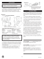
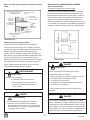
971?5=:9?=:7&1??593>
Desired
Burn Setting
Low
Med/Low
Med/High
High
Inlet
Air Setting
Closed Fully
1/4 Open
3/4 Open
Fully Open
**Approx.
BTU Output
12,000
15,000
19,000
35,000

60-10-001
!)%(&&"!&"!'+#!'%!
(%"&!%"'%("%
& %$(&'"&'%'"%%&!(#
%!'&'%#&($(&
**+%" ''%*'&!(&
&&%
The following use and safety tips should be observed:
1. Inspect the glass regularly for cracks and breaks.
If you detect a crack or break, extinguish the fire
immediately, and contact your dealer for replacement.
2. Do not slam door or otherwise impact the glass.
When closing doors, make sure that logs or other
objects to not protrude and impact the glass.
3. Do not clean the glass with materials which may
scratch (or otherwise damage) the glass. Scratches
on the glass can develop into cracks or breaks.
4. Never attempt to clean the glass while unit is hot. If
the deposit is not very heavy, normal glass cleaners
are adequate with a plain, non-abrasive scouring pad.
Heavier deposits may be removed with the use of a
readily available oven cleaner.
5. Never put substances which can ignite explosively in
the unit since even small explosions in confined areas
can blow out the glass.
6. This unit has an airwash system, designed to reduce
deposits on glass.
REPLACE GLASS ONLY WITH GHP GROUP
REPLACEMENT GLASS (SEE REPLACEMENT
PARTS PAGE 16).
&&%# !'
('"! Make sure fire is out and stove is completely
cool to the touch.
1. Find an area that will ensure safe removal and no
damage to surface of door frame or decorative home fur-
nishing.
2. Wearing a pair of protective gloves, remove the push
nuts that retain the door pins from being pulled out and
then lift the door off of the hinges.
3. Lay the door face down on a protective surface locat-
ed in Step 2.
4. Remove the screws from all glass retainers and
remove the broken glass, ensuring that the door frame is
free from any slivers. (If even small slivers are left, the
new glass will not seal correctly causing the stove to
burn improperly.)
5. Attach glass gasket (from GHP Group replacement
parts page 16) to new glass and install in door frame.
6. Replace glass retainers with screws making sure not
to cross thread or overtighten.
7
. Place door on hinges and replace new push nuts,
purchased from GHP Group, on door pins to ensure door
does not move after reinstall.
&'%# !'
After extensive use, the sealing material which provides
glass and door seal may need to be replaced if it fails to
sustain its resilience. Inspect glass and door seal period-
ically to ensure for proper seal. If gaskets become frayed
or worn, replace immediately.
Contact your dealer or GHP Group Customer Service for
approved replacement parts. The following steps should
be followed for glass gasket replacement:
1. Ensure appliance is not in operation and is thoroughly
cooled.
2. Remove screw and glass clip.
3. Lift glass out from glass clip.
4. Remove old gasket and clean glass.
5. Replace new gasket starting at the bottom of glass
working along edges, being sure to centre gasket
channel on glass.
6. Trim to length and butt ends together.
7. Replace glass in door, being sure not to over-tighten
screw and clip.
The following steps should be followed for door gasket
replacement:
1. Ensure appliance is not in operation and is thoroughly
cooled.
2. Remove old door gasket and clean channel.
3. Using an approved high temperature gasket cement,
apply a thin coat in bottom of channel.
4. Starting at hinge side of door, work into channel
around door unit, end butt and trim to length.
5. Close door and allow three to four hours for cement
to set before restarting appliance.
%"&"'
When wood is burned slowly, it produces tar and other
organic vapours. These combine with moisture to form
creosote. Creosote vapours condense in the relatively
cool chimney flue of a slow-burning fire. As a result,
creosote residue accumulates on the flue lining. When
ignited, this creosote makes an extremely hot fire. The
chimney should be inspected regularly during the heating
season to determine if a creosote build-up has accumu-
lated. If this is the case, the creosote should be removed
to reduce the risk of chimney fire.

60-10-001
*+&'"#%)!'!#(!'%"%"&"'
1. Burn with air control open for several minutes at
numerous intervals throughout the day during the
heating season, being careful not to over-fire unit.
This removes the slight film of creosote accumulated
during low burn periods.
2
. Burn stove with draft control wide open for several
m
inutes every time you apply fresh wood. This
allows wood to achieve the charcoal stage faster
and burns wood vapours which might otherwise be
deposited within the system.
3. BURN ONLY SEASONED WOOD. Avoid burning wet
or green wood. Seasoned wood has been dried for
at least one year.
4. A small hot fire is preferable to a large smouldering
one that can deposit creosote within the system.
5. Establish a routine for the fuel, wood burner and firing
technique. Check daily for creosote build-up until
experience shows how often you need to clean to be
safe. Be aware that the hotter the fire, the less creosote
is deposited and weekly cleanings may be necessary
in mild weather even though monthly cleanings may
be enough in the coldest months. Contact your local
municipal authority for information on how to handle
a chimney fire. Have a clearly understood plan to handle
a chimney fire.
*%!!'4593>?:=1818.1=59/->1:2/45891D25=1
"&%'"!'%"
'%#%' !'
&&#"&
This unit features a convenient ash lip for easy removal of
ash. During constant use, ashes should be removed
every few days, or whenever ashes get to three to four
inches deep in the firebox. Remove ashes only when the
fire has died down and the ashes have cooled. Even
then, expect to find a few hot embers.Ashes should be
placed in a metal container with a tight-fitting lid. The
closed container of ashes should be placed on a non-
combustible floor, well away from all combustible materi-
als, pending final disposal. If the ashes are disposed of
by burial in soil or otherwise locally dispersed, they
should be retained in the closed container until all cin-
ders have thoroughly cooled. Other waste should not be
placed in the ash container.
(&!'&%*%
!"':-7>8-D>?577.14:?1A19?4:@34>?:A12117>
/::7?:?41?:@/4
1. Make sure stove is completely cool.
2
. Open glass door and lift up the firebrick for ash drawer
using a fireplace poker through the metal hook raised
from the top of the brick and set aside in firebox.
3. Using a small hand broom, sweep the ashes into the
opening, allowing the ashes to fall into the ash pan.
4. Make sure all debris is clear of the opening. This is
important to ensure the firebrick (when replaced) seals
to the metal stove bottom. If the fire brick is not
properly sealed, the stove will not operate correctly.
5. Using gloves, pull out the ash drawer while holding the
bottom of the ash pan so it doesn’t fall out onto the
floor.
6. Dispose of the ashes in a metal container with a
tight-fitting lid.
7. Replace ash pan drawer and firebrick to their original
positions.
#"%'!'
#(!'&
*4-?5>?41/:==1/?B-D?:>?-=?-25=1
a) You will need small pieces of dry wood (kindling)
and paper. Use only newspaper or paper that has not
been coated or had unknown materials glued or
applied to it. Never use coated (typically advertising
flyers) or coloured paper.
b) Open the door of the wood stove.
c) Crumple several pieces of paper and place them in
the center of the firebox and directly on to the fire
bricks of the wood stove. Never use a grate to
elevate the fire.
d) Place small pieces of dry wood (kindling) over the
paper in a Teepee manner. This allows for good air
circulation, which is critical for good combustion.
e) Light the crumpled paper in 2 or 3 locations.
Note: It is important to heat the air in the stovepipe
for draft to start.
f) Fully open the air control of the wood stove and
close the door until it is slightly open, allowing for
much needed air to be introduced into the fire box.
Never leave the door fully open as sparks from the
kindling may occur causing injury or property
damage. As the fire begins to burn the kindling,
some additional kindling may be needed to sustain
the fire. DO NOT add more paper after the fire has
started.

60-10-001
g) Once the kindling has started to burn, start by
adding some of your smaller pieces of seasoned (dry)
firewood. NOTE: Adding large pieces at the early
s
tages will only serve to smother the fire. Continue
adding small pieces of seasoned (dry) firewood,
keeping the door slightly open until each piece starts
to ignite. Remember to always open the door slowly
between placing wood into the fire.
h) Once the wood has started to ignite and the smoke
has reduced, close the wood stove door fully. The
reduction of smoke, is a good indication that the draft
in the chimney has started and good combustion is
now possible. Larger pieces of seasoned (dry) fire
wood can now be added when there is sufficient
space in the Firebox. Adjust the air control setting to
desired setting.
I) Note: The lower the air control setting the longer the
burn time of your firewood.
*4-??D;1:2B::05>.1>??:@>1->5=1B::0
Dry seasoned hardwood should be used. Avoid
green unseasoned wood. Green wood, besides
burning at only 60 percent of the fuel value of dry
seasoned wood, will deposit creosote on the inside of
your stove and along the inside of your chimney.
*4-?0:1>0=D>1->:910B::081-9-90B4-?5>
/:9>501=104-=0B::0
Wood that has been dried for a period of one year in
a well-ventilated and sheltered area would be considered
dry seasoned wood. Hardwoods are generally from
slow growth trees (Example: Oak and Fir). Softwoods
are generally from fast growth trees. (Example: Pine
and Spruce)
*5772:77:B593?41-.:A175>?10>?1;>2:=>?-=?593-
25=1=1>@7?59;1=21/?=1>@7?>-77?41?581
The quick answer is most of the time. There are
many variables that may affect your success rate
when staring a fire. Most of those variables and how
to deal with them will be learned through experience.
Your ability to start a good fire will significantly
increase with time and patience. Some of the reasons
for poor stove performance will be covered in the
next section of these instructions.
*4D/-9H?31??4125=175?
Damp or wet wood and poor draft are the main
reasons for poor results in starting a fire. Always use
dry seasoned wood for your fire. Even wood dried for
two years will be difficult to ignite, if it has become wet.
*4D5>?41=1-7B-D>-7-=31<@-9?5?D:2?45/6.7-/6
>8:61;=1>19?59?4125=1.:C
A
large quantity of thick black smoke in the firebox, is
a good indication that the draft is poor.
>5?9:=8-72:=>::??:/:A1=?4137->>-??41
.13599593:2-25=1
Your stove has been built with an air wash system
that will help keep the glass clear when the firebox
has reached a good operating temperature, and has a
good draft. Cold firebox temperature and poor draft
cause sooting of the glass. Once the firebox temperature
and the draft increases, the soot will burn off.
*4-?5>0=-2?
Draft is the ability of the chimney to exhaust draw by-
products produced during the normal combustion
process.
*4-?/-9/-@>1-;::=0=-2?
The most common factors for poor draft are:
a) Atmospheric pressure and air supply
b) Environmental conditions
c) Cold chimney temperature
d) Poor chimney installation and maintenancea)
?8:>;41=5/#=1>>@=1-905=&@;;7D
Atmospheric pressure affecting the draft from a
chimney can be either outside the home, inside the
home or both. Outside the home, a high-pressure
day (clear and cool) generally creates a better draft in
the chimney than a low-pressure day (overcast and
damp). Inside the home, normal household appliances,
such as clothes dryers and forced air furnaces compete
for air resulting in inadequate amounts of air available
to fuel a fire and create a condition known as negative
pressure. Under extreme conditions of negative pressure
the combustion by-products can be drawn from the
chimney and into the house. This condition is commonly
referred to as down drafting.There are several factors
that impact the amount of air available in the home.
Increased amounts of insulation vinyl windows, extra
caulking in various places and door seals can all keep
heat in but may also make a home too airtight. If you
are in doubt about whether or not there is sufficient
air in your home for your stove, refrain from using
those appliances known to consume the air where
possible, or open a window or door to allow air to
enter the home.

60-10-001
9A5=:9819?-7:905?5:9>
High trees, low lying house location such as in a
valley, tall buildings or structures surrounding your
house and windy conditions can cause pool draft or
d
own drafting.
:7045891D'18;1=-?@=1
Avoid cold chimney temperatures by burning a hot
f
ire for the first fifteen to forty minutes, being careful
not to over fire. If any part of the chimney or parts of
the stove start to glow, you are over firing the stove.
Where possible, install a temperature gauge on the
chimney so temperature drops can be seen.
45891D9>?-77-?5:9-90 -59?19-9/1
Avoid using too many elbows or long horizontal runs.
If in doubt, contact a chimney expert and/or chimney
manufacturer for help. Clean chimney, rain caps and
especially spark arrester regularly, to prevent creosote
build-up, which will significantly reduce chimney draw
and may cause a chimney fire.
&4:@70/7:>1:=:;19?41-5=/:9?=:72@77DB419
>4@??5930:B9?41>?:A1
W
hen shutting down the stove, fully open the air
control. This allows the chimney temperatures to
remain as high as possible for as long as possible.
Cold chimney temperatures create creosote.
!"' This sheet is intended as an aid and does not
supersede any local, provincial or state requirements.
Check with officials or authorities having jurisdiction in
your area.

60-10-001
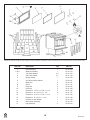
?18!: 1>/=5;?5:9 $?D #-=?!:
1. Door Assembly 1 75-21-503
2. & 3. Glass and Gasket 1 75-21-514
3. 1/8” Glass Gasket 4.3’ 75-21-123
4. 5/8” Door Gasket 5.1’ 75-21-143
5. Spring Handle 1 75-20-140
6. Air Control Spring Handle 1 75-20-141
7. Glass Clip 6 75-25-131
8. Screw 6 75-21-141
9. Hinge Pin 2 75-20-132
10. Push Nut 2 75-21-150
11. Firebrick Lt. 7 3/4” x 4 7/16” x 1 1/4” 4 75-21-145
12. Firebrick Lt. 9” x 4 7/16” x 1 1/4” 15 75-21-147
13. Firebrick Lt. 4 1/2” x 4 7/16” x 1 1/4” 1 75-21-146
14. Firebrick Lt. 9” x 2 1/2” x 1 1/4” 1 75-21-148
15. Firebrick for Ash Drawer 1 75-21-149
16. Ash Drawer Assembly 1 75-21-512
17. Leg Assembly 4 75-22-510
GHP Group reserves the right to make changes in design, materials, specifications, prices and discontinue colors and products at any time, without notice.
Brick Pattern

GHP Group warrants that your new woodburning stove or
masonry wood insert is free from manufacturing and material
defects for a period of five years from the date of sale, subject
t
o the following conditions and limitations.
1. This warranty is extended to the original owner only, for
residential use, and is subject to proof of purchase.
2. The new GHP Group product must be installed and operated
at all times in accordance with the installation and operation
instructions supplied with the appliance, and installation must
be to local and national codes. Any alterations, willful abuse,
accident, over firing or misuse will not be coverd under warran-
ty. NOTE: Some minor movement of certain parts is normal
and is not a defect and therefore, not covered under warranty.
3. The warranty is non-transferable, and is made to the original
owner, provided that the purchase was made through an
authorized GHP Group supplier. The serial number must be
supplied along with the Bill of Sale, showing the date of
purchase, at the time the claim is submitted.
4. This warranty is limited to the repair or replacement of parts
only, found to be defective in material or construction, provided
that such parts have been subjected to normal conditions of
use and service, after a said defect has been confirmed by
GHP Group, or an authorized representative’s inspection.
Defective parts must be shipped back (at GHP Group discre-
tion), transportation prepaid, to the manufacturer. Credits will
be issued upon receipt of return of the defective product to
GHP Group.
5. GHP Group, at its discretion, can fully discharge all obligation
with respect to this warranty by refunding the wholesale price
of the defective part(s).
6. Any installation, labor, construction, transportation or other
related costs or expenses arising from defective parts, repair,
replacement or otherwise of same, will not be covered by this
warranty nor will GHP Group assume responsibility for same.
Further, GHP Group will not be responsible for any incidental,
indirect or consequent damages, except as provided by law,
and in no event shall they exceed the original purchase price.
7. All other warranties - expressed or implied - with respect to
the product, its components and accessories, or any obliga-
tions/liabilities on the part of GHP Group are hereby expressly
excluded.
8. GHP Group neither assumes, nor authorizes any third party
to assume, on GHP Group’s behalf, any other liabilities with
respect to the sale of this GHP Group product.
9. The warranties as outlined within this document do not apply
to chimney components or other products made by other
manufacturers when used in conjunction with the installation
of this product. Improper use or the use of non-approved
components may nullify your warranty. If in doubt, contact
your nearest GHP Group supplier or GHP Group Customer
Service Department.
10. GHP Group will not be responsible for:
• Downdrafts or spillage caused by environmental conditions
such as nearby trees, buildings, rooftops, hills, mountains, or
ineffective chimney design.
• Inadequate ventilation, excessive offsets or negative air
pressure caused by mechanical systems such as furnaces,
clothes dryers, fans, etc.
11. This warranty is void if:
• The appliance has been operated in atmospheres contaminated
by chlorine, fluorine, or other damaging chemicals.
• This appliance has been subjected to prolonged periods of
dampness or condensation.
• The appliance has any damage due to water, or weather
damage that is the result of, but not limited to, improper
chimney/venting installation.
• The appliance has been subjected to willfull or accidental
abuse or misuse.
• Corrosive driftwood, manufactured logs or other fuels are
used other than as outlined in the installation and operating
instructions.
• The appliance is not maintained in good condition, including
firebrick and gaskets.
Doors with Glass and Plated Parts
G
lass is warranted against thermal breakage only. To clean glass,
use a ceramic/glass cleaner or polish. Do not use ammonia
based cleaners. A suitable cleaner is available at your nearest
Pleasant Hearth dealer. DO NOT CLEAN GLASS WHILE HOT
AND DO NOT USE ABRASIVE CLEANERS.
Plated parts will not be covered under this warranty. Plated
parts should be cleaned by using denatured alcohol only and
rubbed lightly with a lint-free non-abrasive cloth. Excessive
rubbing or polishing may remove the plated finish. Plated parts
may also be damaged by external chemicals.
Further Exclusions
This warranty will not include or extend to paint, gaskets or fire-
brick components, and does not cover any removable firebox
components such as brick retainers or stainless steel air tubes.
Electrical Components
GHP Group warranty coverage extends to electrical components
(e.g. blowers, speed controls) also.
IF WARRANTY SERVICE IS REQUIRED
Contact GHP Group Customer Service. Make sure you have
your sales receipt and the model/serial number of your GHP
Group product.
Do not attempt to do any service work yourself, unless pre-
approved by GHP Group in writing as this will void the warranty.
GHP Group must authorize service and provide a Warranty
Claim Number prior to any warranty related service calls.
Without an authorization number, any service work will not be
deemed warranty.
IMPORTANT NOTICE
BEFORE LIGHTING YOUR FIRST FIRE, REMOVE PLASTIC
FILM OFF TRIM AND CLEAN THE PLATED SURFACES WITH
DENATURED ALCOHOL OR A GOOD QUALITY, NON-ABRASIVE
LIQUID GLASS CLEANER. APPLY WITH A VERY SOFT,
CLEAN CLOTH. DO NOT USE PAPER TOWELS TO CLEAN
THE PLATED PARTS. FAILURE TO CLEAN ALL MARKS AND
FINGERPRINTS FROM THE PLATED SURFACES WILL
CAUSE PERMANENT DAMAGE.
NOTE: Some states and provinces do not allow the exclusion or
limitation of incidental or consequential damages. The above
limitations may not apply to you.
GHP Group, Inc. • 8280 Austin Ave. • Morton Grove, IL 60053
KEEP THIS WARRANTY
Serial #_______________________________
Model #________________________
Date Purchased________________________
17
60-10-001
5 Year Warranty

60-10-001
Warming Your Home. Warming Your Heart. raW imr gni oY ruo H emo e aW mra gni Yg ruoY Hr aeH tr raW imr gni oY ruo H emo .e aW mra gni Yg ruoY Hr aeH .tr
8280 Austin Avenue
Morton Grove, IL 60053
877-447-4768
Poêle à bois à haut rendement
Modèle: HWS-230292 - Gros poêle à bois sur socle
Modèle: WS-3029 – Gros poêle à bois sur socle et pieds
Modèle: LWS-130291-B – Gros poêle à bois sur pieds et ventilateur soufflant
Modèle: LWS-130291-BCA – Gros poêle à bois sur pieds et ventilateur soufflant
Manuel du propriétaire
Questions, problèmes, pièces manquantes? Contactez notre service à la clientèle avant
de retourner l’article chez le détaillant : 1-877-447-4768 8h30 à 16h30 HNC
du lundi au vendredi ou envoyez-nous un courriel [email protected].
AVIS DE SÉCURITÉ: CET APPAREIL DE CHAUFFAGE AU BOIS PEUT CAUSER UN INCENDIE DE
MAISON S’IL N’EST PAS BIEN INSTALLÉ, UTILISÉ ET SI ON NÉGLIGE SON ENTRETIEN. SUIVEZ
LES INSTRUCTIONS D’INSTALLATION POUR DIMINUER LES RISQUES D’INCENDIE. LE NON
RESPECT DES INSTRUCTIONS D’INSTALLATION POURRAIT CAUSER DES DOMMAGES AUX
BIENS, DES BLESSURES OU LA MORT. INFORMEZ-VOUS AUPRÈS DU DIRECTEUR RÉGIONAL
DE LA CONSTRUCTION POUR OBTENIR DE L’INFORMATION SUR LES RESTRICTIONS ET LES
EXIGENCES RELATIVES À L’INSPECTION DE L’INSTALLATION DANS VOTRE RÉGION.
Ce manuel porte sur l’installation et l’utilisation du modèle HWS-230292, modèle WS-3029 et du modèle
LWS-130291 (appareil de chauffage au bois non catalytique). Cet appareil de chauffage au bois satisfait aux
normes sur les limites d’émission du United States Environmental Protection Agency (EPA). Dans des condi-
tions spécifiques l’appareil de chauffage génère une puissance de 12 000 à 35 000 Btu/h.
Ce poêle à bois est enregistré par (OMNI-Test Laboratories,
Portland, Oregon) et a satisfait aux normes d’évaluation
américaines et canadiennes UL1482 et ULC-S627.
Conduit de fumée de 1,83 m requis
Ne jetez pas ce manuel: Gardez-le pour consultation

60-10-001
AVERTISSEMENT
U
tilisez les services d’un installateur qualifié et compétent qui sera
en mesure de faire une installation professionnelle et sécuritaire de
l’appareil si vous doutez, suite à la lecture des instructions, de votre
capacité à faire une installation professionnelle et sécuritaire. Ne
faites pas une installation incomplète ou temporaire.
A
VANT L’INSTALLATION DE L’APPAREIL
1.Informez-vous auprès du service d’inspection des constructions
afin de connaître les règlements municipaux. Un permis est parfois
requis.
2.L’appareil de chauffage doit être raccordé à 1) une cheminée qui
satisfait aux normes des cheminées de Type HT et aux normes
générales des cheminées. La cheminée doit être préfabriquée et de
type résidentiel et répondre aux normes des appareils de chauffage
UL 103, et au Canada ULC S627 (norme de 650 degrés Celcius
pour cheminée préfabriquée) et être conforme aux codes et règle-
ments de la construction, ou 2) cheminée en maçonnerie avec dou-
blage de cheminée conforme aux codes et règlements.
3.Un conduit de fumée en métal noir de (152mm) de diamètre et
d’une épaisseur de 24.
4.Il faut toujours raccorder l’appareil à une cheminée; il ne faut
JAMAIS faire évacuer la fumée dans une autre pièce ou à l’intérieur.
5.NE raccordez PAS l’appareil à un tuyau qui est raccordé à un
autre appareil, par ex. une fournaise.
6.NE RACCORDEZ PAS L’APPAREIL À UN CONDUIT DE FUMÉE
QUI EST RACCORDÉ À UN AUTRE APPAREIL.
7.Il faut vérifier régulièrement le raccordement de tuyau et la chem-
inée, et les nettoyer si nécessaire.
8.Il faut tenir compte de la distance de sécurité lors de l’installation
de meubles et d’objets à proximité de l’appareil. NE METTEZ PAS
de bois, liquide inflammable ou combustible près de l’appareil.
Les distances de sécurité sont inscrites sur le sceau d’attestation
qui se trouve à l’arrière de l’appareil.
9.Contactez les services municipaux ou provinciaux de protection
contre l'incendie pour obtenir de l’information sur les incendies de
cheminée. Établissez un plan d’action afin de bien réagir en cas
d’incendie de cheminée. Fermez l’entrée d’air et TÉLÉPHONEZ LE
SERVICE D’INCENDIE en cas d’incendie.
10. Il NE faut PAS forcer la manette d’admission d’air pour modifier
son réglage normal.
11.N’INSTALLEZ PAS CES APPAREILS DANS UNE MAISON
MOBILE OU ROULOTTE. CES APPAREILS NE SONT PAS
APPROUVÉS POUR UTILISATION DANS UNE MAISON MOBILE.
12.NE LE RACCORDEZ PAS À UN TUYAU D’AÉRATION OU
SYSTÈME DE DISTRIBUTION DE L’AIR.
UTILISATION
VOICI POURQUOI IL EST IMPORTANT D’UTILISER UN CONDUIT
DE FUMÉE DE LA BONNE DIMENSION (1,83 M): Le tirage de la
cheminée est le mouvement de l’air dans le conduit, provoqué par
l’attraction de l’oxygène vers une combustion. Le tirage de la
cheminée est fonction de la longueur et de l’emplacement de la
cheminée ainsi que des choses se trouvant à proximité de la chem-
inée et d’autres facteurs. L’appareil peut chauffer de façon exces-
sive si le tirage est trop puissant. Le tirage est trop puissant
l
orsque la combustion est incontrôlable ou lorsque la cheminée ou
les raccordements de cheminée sont rouges vifs. Un tirage insuff-
isant peut repousser la fumée dans la pièce ou « boucher » la
cheminée et/ou laisser la fumée s’échapper par les joints de l’ap-
pareil et de la cheminée.
L
es appareils à combustible solide d’aujourd'hui sont plus effi-
caces. Ces appareils offrent une combustion optimale et dégage
plus de chaleur avec moins de combustible. La cheminée doit être
de la bonne dimension afin d’assurer un tirage efficace puisque les
nouveaux appareils évacuent la fumée à une plus basse tempéra-
ture. L’appareil ne pourra pas augmenter efficacement la tempéra-
ture du conduit de fumée si la cheminée est trop large et le triage
ne sera pas efficace. Il y aura donc un refoulement de fumée et/ou
une combustion inadéquate.
Contactez un expert en entretien de cheminées si vous avez ce
problème.
Lorsque la porte est fermée : vous utilisez la manette d’admission
d’air pour actionner le mécanisme permettant de contrôler l’entrée
d’air dans la chambre à combustion. Vous serez à la longue capa-
ble de contrôler l’intensité de la chaleur et la durée de combustion.
Vous pourrez utiliser l’appareil lorsque le tirage de la cheminée sera
convenable, mais à condition de fermer la porte. Il faut ouvrir la
porte lentement lorsqu’on ajoute le bois afin d’empêcher la fumée
de s’échapper. Une utilisation inappropriée de l’appareil pourrait
occasionner des dommages irréparables, soit une combustion à
une température supérieure aux normes de conception de l’ap-
pareil. Il est recommandé de mettre du bois jusqu’au niveau de la
brique réfractaire.
Une trop grande quantité peut nuire à la circulation de l’air et à la
combustion.
Utilisez cet appareil de chauffage seulement lorsque la porte est
fermée.
NE BRÛLEZ PAS D’ORDURES OU DE LIQUIDES COM-
BUSTIBLES, PAR EX. ESSENCE, NAPHTE, HUILE POUR
MOTEUR. N’UTILISEZ PAS DE PRODUITS CHIMIQUES OU DE
LIQUIDES COMBUSTIBLES POUR ALLUMER LE FEU.
1
IL DOIT TOUJOURS AVOIR DE L’AIR FRAIS DANS LA PIÈCE OÙ SE
TROUVE L’APPAREIL PUISQU’UNE IMPORTANTE DIMINUTION DE
LA QUANTITÉ D’AIR POURRAIT NUIRE AU FONCTIONNEMENT
D’AUTRES APPAREILS À COMBUSTION ET CRÉER UNE SITUA-
TION POTENTIELLEMENT DANGEREUSE.
DÉGAGE UNE CHALEUR. LES ENFANTS NE DOIVENT PAS
S’APPROCHER. LES VÊTEMENTS ET LES MEUBLES NE
DOIVENT PAS SE TROUVER À PROXIMITÉ. PEUT CAUSER
DES BRÛLURES.
VENTILATEUR OPTIONEL : MODÈLE BAR-2427, 120 VOLTS,
60Hz, 0.75 AMP, 2900 T/M DANGER: RISQUE
D’ÉLECTROCUTION.
DÉBRANCHEZ L’APPAREIL AVANT L’ENTRETIEN OU LA
RÉPARATION. IMPORTANT : FAITES FONCTIONNER LE
VENTILATEUR À FAIBLE VITESSE POUR OPTIMALISER LE
FONCTIONNEMENT DE L’APPAREIL DE CHAUFFAGE
LORSQUE LA COMBUSTION EST LENTE.
La page charge ...
La page charge ...
La page charge ...
La page charge ...
La page charge ...
La page charge ...
La page charge ...
La page charge ...
La page charge ...
La page charge ...
La page charge ...
La page charge ...
La page charge ...
La page charge ...
La page charge ...
La page charge ...
La page charge ...
La page charge ...
La page charge ...
La page charge ...
La page charge ...
La page charge ...
La page charge ...
La page charge ...
La page charge ...
La page charge ...
La page charge ...
La page charge ...
La page charge ...
La page charge ...
La page charge ...
La page charge ...
La page charge ...
La page charge ...
-
 1
1
-
 2
2
-
 3
3
-
 4
4
-
 5
5
-
 6
6
-
 7
7
-
 8
8
-
 9
9
-
 10
10
-
 11
11
-
 12
12
-
 13
13
-
 14
14
-
 15
15
-
 16
16
-
 17
17
-
 18
18
-
 19
19
-
 20
20
-
 21
21
-
 22
22
-
 23
23
-
 24
24
-
 25
25
-
 26
26
-
 27
27
-
 28
28
-
 29
29
-
 30
30
-
 31
31
-
 32
32
-
 33
33
-
 34
34
-
 35
35
-
 36
36
-
 37
37
-
 38
38
-
 39
39
-
 40
40
-
 41
41
-
 42
42
-
 43
43
-
 44
44
-
 45
45
-
 46
46
-
 47
47
-
 48
48
-
 49
49
-
 50
50
-
 51
51
-
 52
52
-
 53
53
-
 54
54


Pleasant Hearth HWS-224172MH Series Le manuel du propriétaire
- Catégorie
- Poêles
- Taper
- Le manuel du propriétaire
- Ce manuel convient également à
dans d''autres langues
Documents connexes
-
Pleasant Hearth WS-3029 Le manuel du propriétaire
-
-
-
-
-
-