Faber CYLN15SS600 Manuel utilisateur
- Catégorie
- Hottes
- Taper
- Manuel utilisateur
Ce manuel convient également à

CYLN15SS600
Installation Instructions
Use and Care Information
Instructions d'installation
Utilisez et d'entretien
Instrucciones de instalación
Información de uso y cuidado
CYLINDRA

2
CONTENTS
Section Page
IMPORTANT SAFETY INSTRUCTIONS 3
RANGE HOOD DIMENSIONS 6
INSTALLATION HEIGHT REQUIREMENTS 7
PARTS 8
TOOLS NEEDED 10
VENTING METHOD 11
PREPARING TO MOUNT THE RANGE HOOD 13
INSTALLING WALL SUPPORT 18
CHOOSING VENTING METHOD 19
ATTACH VENTING: OPTION 1 - REAR DUCTING 20
ATTACH VENTING: OPTION 2 - TOP VENTING
24
ATTACH VENTING: OPTION 3 - NON DUCTED RECIRCULATING
26
COMFORT PANEL INSTALLATION
29
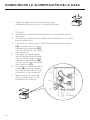
CONNECTING HOUSE POWER
30
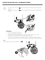
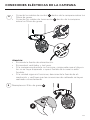
HOOD ELECTRICAL CONNECTIONS
31
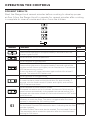
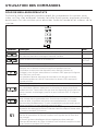
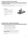
OPERATING THE CONTROLS
32
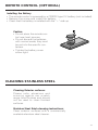
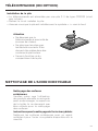
REMOTE CONTROL (OPTIONAL)
33
CLEANING STAINLESS STEEL
33
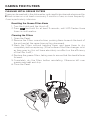
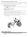
CARING FOR FILTERS
34
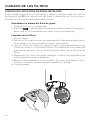
REPLACING BULBS
35
WARRANTY
36

3
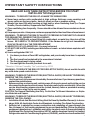
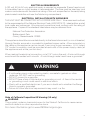
IMPORTANT SAFETY INSTRUCTIONS
READ AND SAVE THESE INSTRUCTIONS BEFORE YOU START
INSTALLING THIS Range Hood
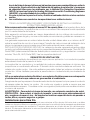
WARNING: - TO REDUCE THE RISK OF A RANGE TOP GREASE FIRE:
a) Never leave surface units unattended at high settings. Boilovers cause smoking and
greasy spillovers that may ignite. Heat oils slowly on low or medium setting.
b)AlwaysturnhoodONwhencookingathighheatorwhenambeingfood(i.e.Crepes
Suzette, Cherries Jubilee, Peppercorn Beef Flambé).
c) Clean ventilating fans frequently. Grease should not be allowed to accumulate on fan or
lter.
d) Use proper pan size. Always use cookware appropriate for the size of the surface element.
WARNING: - TO REDUCE THE RISK OF INJURY TO PERSONS IN THE EVENT OF A RANGE
TOP GREASE FIRE, OBSERVE THE FOLLOWING*:
a)SMOTHERFLAMESwithaclose-ttinglid,cookiesheet,ormetaltray,thenturnoffthe
burner.BECAREFULTOPREVENTBURNS.Iftheamesdonotgooutimmediately
EVACUATE AND CALL THE FIRE DEPARTMENT.
b) NEVER PICK UP A FLAMING PAN - You may be burned.
c) DO NOT USE WATER, including wet dishcloths or towels - a violent steam explosion will
result.
d) Use an extinguisher ONLY if:
1. You know you have a Class ABC extinguisher, and you already know how to operate
it.
2. Thereissmallandcontainedintheareawhereitstarted.
3. Theredepartmentisbeingcalled.
4. Youcanghttherewithyourbacktoanexit.
* Based on "Kitchen Firesafety Tips" published by NFPA
WARNING - TO REDUCE THE RISK OF FIRE OR ELECTRIC SHOCK, do not use this fan with
any solid-state speed control device.
WARNING - TO REDUCE THE RISK OF FIRE, ELECTRICAL SHOCK, OR INJURY TO PERSONS,
OBSERVE THE FOLLOWING:
1. Use this unit only in the manner intended by the manufacturer. If you have any questions,
contact the manufacturer.
2. Before servicing or cleaning unit, switch power off at service panel and lock the service
disconnecting means to prevent power from being switched on accidentally. When the
service disconnecting means cannot be locked, securely fasten a prominent warning
device, such as a tag, to the service panel.
CAUTION: For General Ventilating Use Only. Do Not Use To Exhaust Hazardous or Explo-
sive Materials and Vapors.
WARNING - TO REDUCE THE RISK OF FIRE, ELECTRICAL SHOCK, OR INJURY TO PERSONS,
OBSERVE THE FOLLOWING:
1. InstallationWorkAndElectricalWiringMustBeDoneByQualiedPerson(s)InAccor-
dance With All Applicable Codes And Standards, Including Fire-Rated Construction.
2. Sufcientairisneededforpropercombustionandexhaustingofgasesthroughthe
ue(chimney)offuelburningequipmenttopreventbackdrafting.Followtheheating
equipment manufacturer's guideline and safety standards such as those published by
the National Fire Protection Association (NFPA), and the American Society for Heating,
Refrigeration and Air Conditioning Engineers (ASHRAE), and the local code authorities.

4
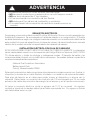
ALL WALL AND FLOOR OPENINGS WHERE THE Range Hood IS INSTALLED
MUST BE SEALED.
This Range Hood requires at least 24" of clearance between the bottom of the Range
Hood and the cooking surface or countertop. This hood has been approved by UL at this
distance from the cooktop.
This minimum clearance may be higher depending on local building codes. For gas cooktops
and combination ranges, a minimum of 30" is recommended and may be required.
Overhead cabinets on both sides of this unit must be a minimum of 18" above the cooking
surface or countertop. Consult the cooktop or range installation instructions given by the
manufacturer before making any cutouts.
MOBILE HOME INSTALLATION The installation of this Range Hood must conform to the
Manufactured Home Construction and Safety Standards, Title 24 CFR, Part 3280 (formerly
Federal Standard for Mobile Home Construction and Safety, Title 24, HUD, Part 280). See
Electrical Requirements"
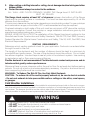
• Venting system MUST terminate outside the home.
• DO NOT terminate the ductwork in an attic or other enclosed space.
• DO NOT use 4" laundry-type wall caps.
• Flexible-type ductwork is not recommended.
• DO NOT obstruct the ow of combustion and ventilation air.
• Failure to follow venting requirements may result in a re.
WARNING
!
VENTING REQUIREMENTS
Determine which venting method is best for your application. Ductwork can extend either
through the wall or the roof.
The length of the ductwork and the number of elbows should be kept to a minimum to
provide efcient performance. The size of the ductwork should be uniform. Do not install
two elbows together. Use duct tape to seal all joints in the ductwork system. Use caulking
to seal exterior wall or oor opening around the cap.
Flexible ductwork is not recommended. Flexible ductwork creates back pressure and air
turbulence that greatly reduces performance.
Make sure there is proper clearance within the wall or oor for exhaust duct before making
cutouts. Do not cut a joist or stud unless absolutely necessary. If a joist or stud must be cut,
then a supporting frame must be constructed.
WARNING - To Reduce The Risk Of Fire, Use Only Metal Ductwork.
CAUTION-Toreduceriskofreandtoproperlyexhaustair,besuretoductairoutside
– Do not vent exhaust air into spaces within walls or ceilings or into attics, crawl spaces,
or garages.
Cold Weather installations
An additional back draft damper should be installed to minimize backward cold air ow and a nonme-
tallic thermal break should be installed to minimize conduction of outside temperatures as part of the
vent system. The damper should be on the cold air side of the thermal break. The break should be as
close as possible to where the vent system enters the heated portion of the house.
3. When cutting or drilling into wall or ceiling, do not damage electrical wiring and other
hidden utilities.
4. Ducted fans must always be vented to the outdoors.

5
ELECTRICAL REQUIREMENTS
A 120 volt, 60 Hz AC-only electrical supply is required on a separate 15 amp fused circuit.
A time-delay fuse or circuit breaker is recommended. The fuse must be sized per local
codes in accordance with the electrical rating of this unit as specied on the serial/rating
plate located inside the unit near the eld wiring compartment.
ELECTRICAL INSTALLATION WITH WIRING BOX
THIS UNIT MUST BE CONNECTED WITH COPPER WIRE ONLY. Wire sizes must conform
to the requirements of the National Electrical Code, ANSI/NFPA 70 - latest edition, and all
local codes and ordinances. Wire size and connections must conform with the rating of
the appliance. Copies of the standard listed above may be obtained from:
National Fire Protection Association
Batterymarch Park
Quincy, Massachusetts 02269
This appliance should be connected directly to the fused disconnect (or circuit breaker)
through exible, armored or nonmetallic sheathed copper cable. Allow some slack in
the cable so the appliance can be moved if servicing is ever necessary. A UL Listed,
1/2" conduit connector must be provided at each end of the power supply cable (at
the appliance and at the junction box).
When making the electrical connection, cut a 1 1/4" hole in the wall. A hole cut through
wood must be sanded until smooth. A hole through metal must have a grommet.
• Electrical ground is required on this Range Hood.
• If cold water pipe is interrupted by plastic, nonmetallic gaskets or other
materials, DO NOT use for grounding.
• DO NOT ground to a gas pipe.
• DO NOT have a fuse in the neutral or grounding circuit. A fuse in the neutral
or grounding circuit could result in electrical shock.
• Check with a qualied electrician if you are in doubt as to whether the Range
Hood is properly grounded.
• Failure to follow electrical requirements may result in a re.
WARNING
!
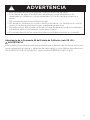
State of California Proposition 65 Warning (US only)
WARNING
This product contains chemicals known to the State of California to cause cancer
and birth defects or other reproductive harm.
For more information go to www.P65Warnings.ca.gov

6
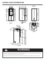
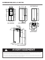
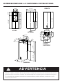
RANGE HOOD DIMENSIONS
PERSONAL INJURY HAZARD
Because of the weight and size of the Range Hood canopy, two or more people are needed
to move and safely install the Range Hood canopy.
Failure to properly lift Range Hood could result in damage to the product or personal injury.
WARNING
!
Version 07/11- Page 5
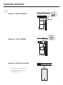
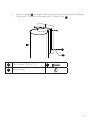
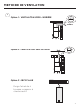
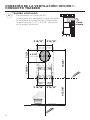
PRODUCT DIMENSIONS
14 9/16”
35 1/16”
13 3/4”
21 1/4”
17 1/8”
4 7/16”
9 13/16”
6 11/16”
5”
6 1/8”
5 3/4”
6 7/8”
27 3/16”
6 7/8”
18 5/16” 15 3/8”
21 1/4”13 3/4”
35 1/16”
9 13/16”
5 3/4”
17 1/8”
4 7/16”
7 7/8”
6 11/16”
14 9/16”
9 7/8”
17 1/8”
9 13/16”
14 9/16”
6 1/8”
5 1/16”
FRONT
SIDE
TOP
BACK
OVERALL
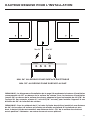
NOTE: The installation diagram in FIGURE 4 on the next page is used for the recommended installation height
of 24" off the cooktop. For maximum installation heights of up to 30" off the cooktop, add onto the horizontal
line of 42 5/16" in FIGURE 4. For example add 6", or 48 5/16" total, to install 30" off the cooktop.
NOTE: For 8" ceilings, the Cylindra should be installed at 24" off the cooktop and the hood is mounted at the
ceiling. For higher ceilings, the Cylindra is mounted at 24 - 30" off the cooktop and is installed "floating" in
the middle of the wall, not at the ceiling.
BACK SIDE
TOP
FRONT
OVERALL

7
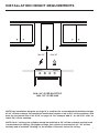
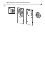
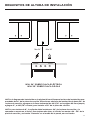
INSTALLATION HEIGHT REQUIREMENTS
MIN. 24" OVER ELECTRIC
MIN. 30" OVER GAS
NOTE: the installation diagram on page 14 is used for the recommended installation height
of 24" off the cooktop. For maximum installation heights of up to 30" off the cooktop, add
onto the horizontal line of 42 5/16" on page 14. For example add 6", or 48 5/16" total, to
install 30" off the cooktop.
NOTE: for 8" ceilings, the cylindra should be installed at 24" off the cooktop and the hood
is mounted at the ceiling. For higher ceilings, the cylindra is mounted at 24 - 30" off the
cooktopandisinstalled"oating"inthemiddleofthewall,notattheceiling.
Min.24” Min.30”

8
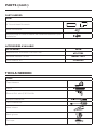
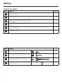
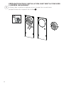
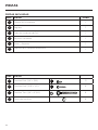
PARTS
REF. PART
QTY
A
Hood body
1
B
Damper
1
C
PVC ductless pipe
1
D
Ductless Grille
1
F
Motor and Support
1
M
Support Range Hood
1
REF
PART
G
Pozi Screws (1/8" x 3/8")
2
H
Pozi Screws (3/16" x 1/2")
4
I
Torx Screws (1/4" x 2 3/4")
4
L
Screws plug
4
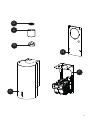
PARTS INCLUDED

9
B
A
F
M
C
D

10
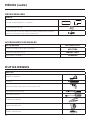
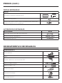
PARTS NEEDED
PARTS (cont.)
PART
6" Round Metal Ductwork
Wire connectors.
Drywall plugs or other suitable wall fasteners based on your
installation.
TOOLS NEEDED
TOOL
Tape Measure
Pencil
Electric Drill with 5/16" Drill Bit
Phillips Screwdriver
Torx Screwdriver
Metal sheers
Work gloves
Foil tape
ACCESSORIES AVAILABLE
ACCESSORY
SKU#
Replacement Activated Charcoal Filter
#FILTER2
Wireless Remote Control
#REMCTRL2
CFM Reducer Kit
CFMRED2

11
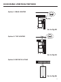
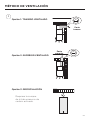
VENTING METHOD
Option 1: REAR VENTED
Option 2: TOP VENTED
Option 3: RECIRCULATING
Rear
ø 120 mm
ø 150 mm
2x
ø 150 mm
2x
W
550 mm550 mm
7"
1
Requires purchase of
Activated Charcoal
Accessory kit.
ø 120 mm
ø 150 mm
2x
ø 150 mm
2x
W
550 mm550 mm
7"
Top
ø 120 mm
ø 150 mm
2x
ø 150 mm
2x
W
550 mm550 mm

12
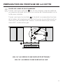
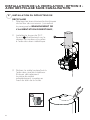
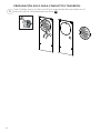
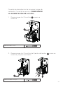
PREPARATION FOR REAR DUCTING ONLY.
Use metal sheers to cut the pre-scored hole in the Range Hood Support
M
.
2

13
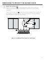
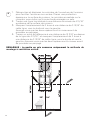
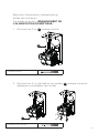
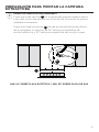
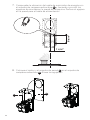
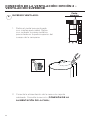
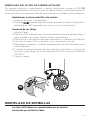
PREPARING TO MOUNT THE RANGE HOOD
DRAW POSITIONING LINES
Draw a vertical line
H
on the supporting wall to the ceiling or
upper limit, at the center of the area in which the hood will be
installed.
Draw a horizontal line
I
where the bottom edge of the hood will
be located, a minimum of 24" above an electric cooking surface
and 30" above a gas cooking surface.
3
MIN. 24" OVER ELECTRIC/MIN. 30" OVER GAS
I
H

14
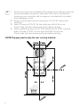
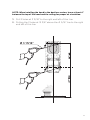
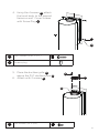
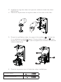
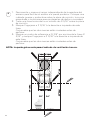
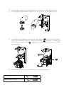
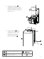
1. Disconnect and move freestanding range from cabinet opening
to provide easier access to rear wall. Put a thick, protective
covering over cooktop, set-in range or countertop to protect
from damage or dirt.
2. Draw a Horizontal line at a minimum of 41 5/16" above the
Cooktop.
3. Mark 2 holes at 3 15/16" to the right and left of this line.
Check that the two marks are level, before drilling.
4. Mark a reference point at 15 3/8" above the 41 5/16" line and
mark 2 holes 3 15/16" to the right and left of this line.
Check that the two marks are level, before drilling.
4
NOTE:The grey part is only for rear venting method.
30" 24"

15
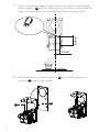
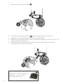
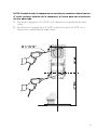
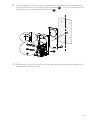
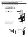
NOTE: When installing the hood in the ductless version, leave at least 4"
between the top of the hood and the ceiling for proper air circulation.
Ø 3 15/16”
5. Drill 2 holes at 3 15/16" to the right and left of this line.
6. Drilling the 2 holes at 15 3/8" above the 41 5/16" line to the right
and left of this line.

16
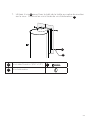
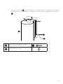
1 15/16”
6 13/16”
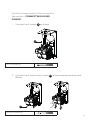
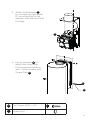
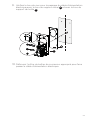
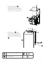
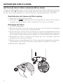
7. Verify the Power Supply Cable location using the Hood Range
Hood Support
M
and by matching up the corner wall mounting
holes. Drill the hole in the wall for the Power Supply Cable
F
M
8. Place the Motor and Wall Support
F
into the Range Hood
Support
M
.Line up the holes..

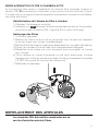
17
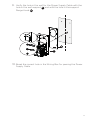
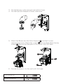
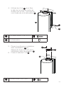
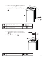
1 15/16”
6 13/16”
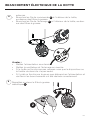
10. Break the correct hole in the Wiring Box for passing the Power
Supply Cable.
F
M
9. Verify the hole in the wall for the Power Supply Cable with the
hole in the wall support
F
and with the hole in the support
Range Hood
M
.

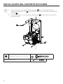
18
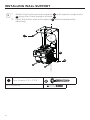
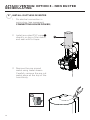
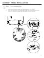
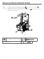
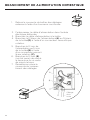
I
Torx Screws (1/4" x 2 3/4")
I
5
INSTALLING WALL SUPPORT
1. Attach the motor and wall support
F
with support range hood
M
using the 4 wall support screws
I
.
2. Level the motor and wall support
F
before permanently
attaching.
F
M
Torx Screwdriver

19
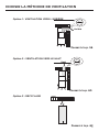
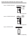
CHOOSING VENTING METHOD
Option 1: REAR VENTED
Option 2: TOP VENTED
Option 3: RECIRCULATING
Rear
ø 120 mm
ø 150 mm
2x
ø 150 mm
2x
W
550 mm550 mm
7"
ø 120 mm
ø 150 mm
2x
ø 150 mm
2x
W
550 mm550 mm
7"
Top
ø 120 mm
ø 150 mm
2x
ø 150 mm
2x
W
550 mm550 mm
Go to Pg.20
Go to Pg.24
Go to Pg.26

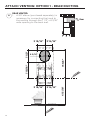
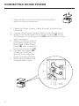
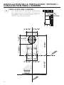
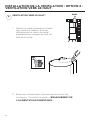
20
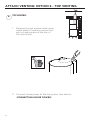
REAR VENTED:
1. A 90° elbow (purchased separately) is
necessary for connecting the hood to
the venting through the 7 1/2" x 6 5/16"
wide opening to the back wall.
6
ATTACH VENTING: OPTION 1 - REAR DUCTING
Rear
ø 120 mm
ø 150 mm
2x
ø 150 mm
2x
W
550 mm550 mm
3 15/16” 3 15/16”
3 15/16” 3 15/16”
15 3/8”
41 5/16”
7 15/16” 7 1/2”
6 5/16”
La page charge ...
La page charge ...
La page charge ...
La page charge ...
La page charge ...
La page charge ...
La page charge ...
La page charge ...
La page charge ...
La page charge ...
La page charge ...
La page charge ...
La page charge ...
La page charge ...
La page charge ...
La page charge ...
La page charge ...
La page charge ...
La page charge ...
La page charge ...
La page charge ...
La page charge ...
La page charge ...
La page charge ...
La page charge ...
La page charge ...
La page charge ...
La page charge ...
La page charge ...
La page charge ...
La page charge ...
La page charge ...
La page charge ...
La page charge ...
La page charge ...
La page charge ...
La page charge ...
La page charge ...
La page charge ...
La page charge ...
La page charge ...
La page charge ...
La page charge ...
La page charge ...
La page charge ...
La page charge ...
La page charge ...
La page charge ...
La page charge ...
La page charge ...
La page charge ...
La page charge ...
La page charge ...
La page charge ...
La page charge ...
La page charge ...
La page charge ...
La page charge ...
La page charge ...
La page charge ...
La page charge ...
La page charge ...
La page charge ...
La page charge ...
La page charge ...
La page charge ...
La page charge ...
La page charge ...
La page charge ...
La page charge ...
La page charge ...
La page charge ...
La page charge ...
La page charge ...
La page charge ...
La page charge ...
La page charge ...
La page charge ...
La page charge ...
La page charge ...
La page charge ...
La page charge ...
La page charge ...
La page charge ...
La page charge ...
La page charge ...
La page charge ...
La page charge ...
La page charge ...
La page charge ...
La page charge ...
La page charge ...
-
 1
1
-
 2
2
-
 3
3
-
 4
4
-
 5
5
-
 6
6
-
 7
7
-
 8
8
-
 9
9
-
 10
10
-
 11
11
-
 12
12
-
 13
13
-
 14
14
-
 15
15
-
 16
16
-
 17
17
-
 18
18
-
 19
19
-
 20
20
-
 21
21
-
 22
22
-
 23
23
-
 24
24
-
 25
25
-
 26
26
-
 27
27
-
 28
28
-
 29
29
-
 30
30
-
 31
31
-
 32
32
-
 33
33
-
 34
34
-
 35
35
-
 36
36
-
 37
37
-
 38
38
-
 39
39
-
 40
40
-
 41
41
-
 42
42
-
 43
43
-
 44
44
-
 45
45
-
 46
46
-
 47
47
-
 48
48
-
 49
49
-
 50
50
-
 51
51
-
 52
52
-
 53
53
-
 54
54
-
 55
55
-
 56
56
-
 57
57
-
 58
58
-
 59
59
-
 60
60
-
 61
61
-
 62
62
-
 63
63
-
 64
64
-
 65
65
-
 66
66
-
 67
67
-
 68
68
-
 69
69
-
 70
70
-
 71
71
-
 72
72
-
 73
73
-
 74
74
-
 75
75
-
 76
76
-
 77
77
-
 78
78
-
 79
79
-
 80
80
-
 81
81
-
 82
82
-
 83
83
-
 84
84
-
 85
85
-
 86
86
-
 87
87
-
 88
88
-
 89
89
-
 90
90
-
 91
91
-
 92
92
-
 93
93
-
 94
94
-
 95
95
-
 96
96
-
 97
97
-
 98
98
-
 99
99
-
 100
100
-
 101
101
-
 102
102
-
 103
103
-
 104
104
-
 105
105
-
 106
106
-
 107
107
-
 108
108
-
 109
109
-
 110
110
-
 111
111
-
 112
112


Faber CYLN15SS600 Manuel utilisateur
- Catégorie
- Hottes
- Taper
- Manuel utilisateur
- Ce manuel convient également à
dans d''autres langues
- English: Faber CYLN15SS600 User manual
- español: Faber CYLN15SS600 Manual de usuario
Documents connexes
-
Faber CYLNIS15SS600 Manuel utilisateur
-
-
-
-
-
-
-