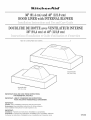
KitchenAid KHVU761RSS1 Le manuel du propriétaire
- Catégorie
- Hottes
- Taper
- Le manuel du propriétaire
Ce manuel convient également à

48' (121.9cm)
avec
36' (91,4) et 48" (121,9cm)
TaMe of Contents/Table des matieres ............................................................................. 2
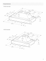
Model/Modete
48" (121,9 cm)
Model/ModUle
36" (91,4 cm)
IMPORTANT: READ AND SAVE THESE INSTRUCTIONS,
FOR RESIDENTIAL USE ONLY.
IMPORTANT : LIRE ET CONSERVER DES INSTRUCTIONS,
POUR UTILISATION RESIDENTIELLE UNIQUEMENT.
IMPORTANT:
Installer: Leave installation instructions with the homeowner.
Homeowner: Keep installation instructions for future reference.
Save installation instructions for local inspector's use.
IMPORTANT :
lnstallateur : Remettre les instructions d'instailation au proprietaire.
PropriStaRe : Conserver les instructions d'installation pour consultation uit_rieure.
Conserver les instructions d'instatlation pour consultation par I'inspecteur local.
9763388

TABLEOF CONTENTS
RANGE HOOD SAFETY ............................... 2
iNSTALLATiON REQUIREMENTS ....................... 4
Tools and Parts ..................................... 4
Location Requirements ............................. 4
Venting Requirements .............................. 6
Electrical Requirements ............................. 7
iNSTALLATiON iNSTRUCTiONS ........................ 7
Prepare Location .................................. 7
Make Electrical Connection .......................... 8
Complete installation ............................... 9
Check Operation .................................. 9
RANGE HOOD USE .................................. 10
Operation ....................................... 10
RANGE HOOD CARE ................................ 10
Cleaning and Maintenance ......................... 10
Accessories ..................................... 10
REQUESTING ASSISTANCE OR SERVICE .............. 1t
RANGE HOOD WARRANTY ........................... 12
WiRiNG DIAGRAM .................................. 13
TABLEDESMATIF,RES
S_:CURITE DE LA HOTTE DE CUISINI_:RE .............. 14
EXIGENCES D'INSTALLATION ........................ 16
Outillage et pieces .................................. 16
Exigences d'emplacement .......................... 16
Exigences concernant I'evaeuation ................... 18
Specifications ebctriques .......................... 19
INSTRUCTIONS DqNSTALLATION ..................... 20
Preparation de I'emplacement ....................... 20
Raccordement electrique ........................... 20
Achever I'installation .............................. 21
Contr61e du fonctionnement ........................ 21
UTILISATiON DE LA HOTTE DE CUISINIERE ............ 22
Fonctionnement .................................. 22
ENTRETIEN DE LA HOTTE DE CUISINIERE ............. 22
Nettoyage et entretien ............................. 22
Accessoires ..................................... 23
DEMANDE D'ASSlSTANCE OU DE SERVICE ............ 24
GARANTIE DE LA HOTTE DE CUISINIERE .............. 25
SCHEMA DE CABLAGE .............................. 26
RANGEHOODSAFETY
Your safety and the safety of others are very important.
We have provided many important safety messages in this manual and on your appliance. Always read and obey all safety
messages.
This is the safety alert symbol.
This symbol alerts you to potential hazards that can kill or hurt you and others.
All safety messages will follow the safety alert symbol and either the word "DANGER" or "WARNING."
These words mean:
You can be killed or seriously injured if you don't immediately'
follow instructions.
You can be killed or seriously injured if you don't follow
instructions.
All safety messages will tell you what the potential hazard is, tell you how to reduce the chance of injury, and tell you what can
happen if the instructions are not followed.

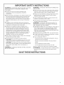
iMPORTANT SAFETY iNSTRUCTiONS
WARNmNG: TO REDUCE THE RiSK OF FIRE, ELECTRIC
SHOCK, OR iNJURY TO PERSONS, OBSERVE THE
FOLLOWING:
m Use this unit only in the manner intended by the
manufacturer, if you have questions, contact the
manufacturer.
m Before servicing or cIeaning the unit, switch the power off at
the service panel disconnecting means to prevent power
from being switched on accidentaiIy. When the service
disconnecting means cannot be locked, securely fasten a
prominent warning device, such as a tag, to the service
panel.
m installation work and electrical wiring must be done by
qualified person(s) in accordance with alI applicable codes
& standards, including fire-rated construction.
m Sufficient air is needed for proper combustion and
exhausting of gases through the flue (cMmney) of fuel
burning equipment to prevent backdrafting. Follow the
heating equipment manufacturer's guideline and safety
standards such as those published by the National Fire
Protection Association (NFPA), the American Society for
Heating, Refrigeration and Air Conditioning Engineers
(ASHRAE), and the local code authorities.
m When cutting or drilling into walI or ceiling; do not damage
electrical wiring and other utilities.
m Ducted systems must always be vented outdoors.
CAUTION: For general ventilating use only. Do not use
to exhaust hazardous or explosive materials and vapors.
CAUTmON: To reduce risk of fire and to properly exhaust
air, be sure to duct air outside - do not vent exhaust air into
spaces within walls ceilings, attics, crawl spaces, or
garages.
WARNING: TO REDUCE THE RiSK OF FIRE, USE ONLY
METAL DUCTWORK.
WARNING: TO REDUCE THE RiSK OF A RANGE TOP
GREASE FIRE:
m Never Ieave the surface units unattended at high settings.
Boilovers cause smoking and greasy spiIIovers that may
ignite. Heat oils siowiy on low or medium settings.
m Always turn hood ON when cooking at high heat or when
flameing food (i.e. Crepes Suzette, Cherries Jubilee,
Peppercorn Beef Flamb@.
m Clean ventilating fans frequently. Grease shouId not be
allowed to accumulate on fan or fiIter.
m Use proper pan size. Always use cookware appropriate for
the size of the surface element.
WARNING: TO REDUCE THE RISK OF iNJURY TO
PERSONS iN THE EVENT OF A RANGE TOP GREASE
FIRE, OBSERVE THE FOLLOWING: _
m SMOTHER FLAMES with a close fitting Iid, cookie sheet, or
other metal tray, then turn off the gas burner or electric
element. BE CAREFUL TO PREVENT BURNS. if the
flames do not go out immediately, EVACUATE AND CALL
THE FiRE DEPARTMENT.
m NEVER PiCK UP A FLAMING PAN _you may be burned.
m DO NOT USE WATER, including wet dishcloths or towels -
a vioIent steam explosion will result.
m Use an extinguisher ONLY if:
- You know you have a class ABC extinguisher, and you
already know how to operate it.
- The fire is small and contained in the area where it
started.
- The fire department is being called.
- You can fight the fire with your back to an exit.
aBased on "Kitchen Fire Safety Tips" published by NFPA.
® WARNING: To reduce the risk of fire or electrical shock,
do not use this fan with any solid-state speed control
device.
SAVE THESE iNSTRUCTiONS

INSTALLATIONREQUIREMENTS
Gather the required tools and parts before starting installation.
Read and follow the safety instructions provided with any tools
listed here.
Tools needed:
level
drill with 11/4"and %2" drill bits
pencil
wire stripper or utility knife
measuring tape or ruler
pliers
caulking gun and weatherproof caulking compound
duct tape
jig saw or keyhole saw
flat blade screwdriver
metal snips
Phillips screwdriver
Parts needed:
3/4"(19.0 mm) UL- or CSA-listed strain relief
power supply cable
metal vent system
IMPORTANT: Observe all governing codes and ordinances.
Hood location should be away from strong draft areas, such as
windows, doors and strong heating vents.
Installation clearance dimensions that are shown must be used.
Given dimensions provide minimum clearance.
NOTE: Hood liner must be surrounded by a custom built
enclosure.
Cooktop to hood clearance wilI depend on the material the
builder uses to enclose the liner.
Grounded electrical outlet is required. See "Electrical
requirements" section.
It is recommended that the hood be fastened to solid wood.
The hood is factory set for venting through the roof or wall.
All openings in ceiling and wall where the hood will be installed
must be sealed.
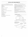
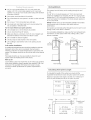
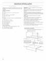
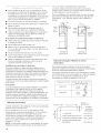
Installation Clearances
min, cabinet opening widths:
36" (91.4 cm) model, 36" (91.4 cm)
48" (121.9 cm) model, 48" (121,9 cm)
hood support must be capable of
supporting 40 Ibs. (18,1 kg) for |
36" (91,4 cm)modelor55Ibs,(25 kg) |
for48"(121,9 cm) model recommended24"to 36"
(61,0 cmto91.4cm)
above cooktop
hood liner is
22' (55.9 cm)
deep

.s
, /
\

[] 36" (91.4 cm) model requires a 6" (15.2 cm) round vent
system. 48" (121.9 cm) model requires two 6" round vent
systems or a 10" (25.4 cm) round system using vent transition
kit number 4396915.
[] Vent system must terminate to the outside.
[] Do not terminate the vent system in an attic or other enclosed
area.
[] Do not use 4" (10.2 cm) laundry-type wall caps.
[] Use metal vent only. Rigid metal vent is recommended. Do
not use plastic or metal foii vent.
For the most efficient and quiet operation:
[] Use a straight run or as few elbows as possible.
[] Use no more than three 90° elbows.
[] Make sure there is a minimum of 24" (61 cm) of straight vent
between the elbows if more than one elbow is used.
[] Do not install two elbows together.
[] Use duct tape to seal all ioints in the vent system.
[] Use caulking to seal exterior wall or roof opening around
the cap.
Cold weather instammations
An additional backdraft damper should be installed to minimize
backward cold air flow and a nonmetallic thermal break to
minimize conduction of outside temperatures as part of the vent
system. The damper should be on the cold air side of the thermal
break.
The break should be as close as possible to where the vent
system enters the heated portion of the house.
Make up air
Local building codes may require the use of make-up air systems
when using ventilation systems greater than specified CFM of air
movement. The specified CFM varies from locale to locale.
Consult your HVAC professional for specific requirements in
your area.
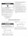
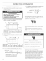
Venting Methods
This canopy hood is factor},, set for venting through the roof
or wail.
The 36" (91.4 cm) model requires a 6" (15.2 cm) round vent
system for installation (not included). The 48" (121.9 cm) model
requires two 6" (15.2 cm) round vent systems or a 10" (25.4 cm)
round vent system for installation. The hood exhaust opening is
6" (15.2 cm) round.
NOTE: Flexible vent is not recommended. Flexible vent creates
back pressure and air turbulence that greatly reduces
performance.
Vent system can terminate either through the roof or wall. To vent
through a wall, a 90° elbow is needed.
For recirculating installations, make sure the hood exhausts back
into kitchen, not into spaces within wall, ceilings, attics, crawl
spaces or garages.
.fJ roof cap
(15,2crn)
round vent
Roof venting Wall venting
wall cap
CaJcutating Vent System Length
To calculate the length of the system you need, add the
equivalent feet (meters) for each vent piece used in the system.
Maximum equivalent vent length is 35 feet (10.7 meters) for 6"
(15.2 cm) vent, 60 feet (18.3 m) for 10" (25.4 cm) vent.
Vent piece
450elbow
6" (152 cm) round or
10" (25.4 cm) round
2.5 feet
(0.8 m) ............
900elbow 5.0 feet
(1.5 m)
90° elbow _6 ft. (1,8 m)----------_l wall cap
_X'_ _' _ Example vent
2ft, I I 1 -- 90 elbow = 5 ft. (1.5 m)
(06 m)
I I 8 ft. (2.4 m) straight = 8 ft. (2.4 m)
1 -- wail cap = 0 ft. (0 m)
h=J system length = 13 ft. (3.9 m)

ElectricalShockHazard
Disconnectpower before servicing,
Replace all parts and panels before operating,
Failure to do so can result in death or electrical shock.
IMPORTANT: The hood must be electrically grounded in
accordance with Iocal codes and ordinances, or in the absence of
local codes, with the National Electrical Code, ANSI/NFPA 70,
latest edition, or Canadian Electrical Code, CSA C22.1, latest
edition.
If codes permit and a separate ground wire is used, it is
recommended that a qualified electrical installer determine that
the ground path is adequate.
A copy of the above code standards can be obtained from:
National Fire Protection Association
One Batterymarch Park, Quincy, MA 02269
CSA International
8501 East Pleasant Valley Road
Cleveland, Ohio 44131-5575
[] A 120-volt, 60-Hz, AC-only, 15-amp, fused electrical circuit is
required. A time-delay fuse or circuit breaker is also
recommended. It is recommended that a separate circuit
serving only this hood be provided.
[] Do not ground to a gas pipe.
[] Check with a qualified electrician if you are not sure range
hood is properly grounded.
[] Do not have a fuse in the neutral or ground circuit.
[] The range hood must be connected with copper wire only.
[] The range hood should be connected directly to the fused
disconnect (or circuit breaker) box through flexible armored or
nonmetallic sheathed copper cable.
[] A UL- or CSA-Iisted strain relief must be provided at each end
of the power supply cable. Wire sizes (copper wire only) and
connections must conform with the rating of the appliance as
specified on the model/serial rating plate.
[] Wire sizes must conform to the requirements of the National
Electrical Code, ANSI/NFPA 70, latest edition, or CSA
Standards C22.1-94, Canadian Electrical Code, Part 1 and
C22.2 No. 0-M91, latest edition, and all local codes and
ordinances.
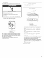
INSTALLATIONiNSTRUCTiONS
[]
Cover countertop or cooking surface with a thick, protective
covering to prevent damaging them.
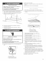
Mark the locations of the four %2" (5.6 mm) dia. holes on the
hood support as shown.
I I
2sA,,
2. Drill the four holes.
3. Provide a rectangular clearance hole for the blower motor
housing.
23/4 _
wall
Hood size A B C
36" (91.4 cm) 28" (71.1 cm) 14" (35.5 cm) 16" (40.6 cm)
48" (121.9 cm) 36" (91.4 cm) 18" (45.7 cm) 14_A'' (36.8 cm)
17qe"
Hood size A B
36" (91.4 cm) 317/_6"(79.9 cm) 152%2'' (39.9 cm)
48" (121.9 cm) 437/_6'' (110.3 cm) 212%#, (55.2 cm)

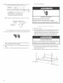
4,
5,
if using the rear electrical knockout, drill a 11/4"(3.0 cm)
dia. hole through the wall at the location shown.
hood support centerline I
ofhood
I
I
I
Hood size A
36" (91.4 cm) 14s/!6'' (36.0 cm)
48" (121.9 cm) 201/4'' (51.4 cm)
I
2'*(5,1 cm)
,
If using the top electrical knockout, drill a 11/4" (3.0 cm)
hood support-_-======_ !-.
(top view) T -_--_ h 2='=(5"1ore)
rightrear hood.............................i_l
mountinghole _ _-_
1W' I
(3_8cm) I
dia. hole through the hood support at the location shown.
Remove the filters. Use two hands to remove filter. Push tab
back to release the locking pin, pull down and forward. Set
filter aside. Repeat with other filter(s).
6, Remove the wiring box cover located behind the right hand
filter.
7, Install UL- or CSA-listed strain relief in hood liner so that
screws can be tightened.
Electdcam Shock Hazard
Disconnect power before servicing.
Replace aH parts and panems before operating,
Failure to do so can result in death or electricam shock,
f,
2,
Disconnect power.
Run power supply cable to the hood electrical hole according
the National Electrical Code or CSA Standards and local
codes and ordinances. There must be enough power supply
cable from the fused disconnect (or circuit breaker) box to
make the connection in the hood's electrical wiring box.
3, Remove the four mounting screws from the parts bag. It is
recommended they be placed by the holes in the hood liner
support for quick access.
4, While feeding the wiring through the strain relief, lift the hood
\\\

liner into place.
5, insert the screws through the support and thread into the
Electricam Shock Hazard
EmectricaHy ground the Mower,
Connect ground wire to green ground screw in
wiring box,
Failure to do so can result in death or electrica{ shock,
hood liner holes. Tighten screws securely.
A B
A,Groundscrewconnector
B,Groundwire
C.Powersupplycable
6, Use twist-on connectors and connect black wires together.
7, Use twist-on connectors and connect white wires together.
8, Connect green or bare wire to the ground screw connector.
9, Tighten strain relief securely.
10, Replace wiring box cover. Tighten screw securely.
11, Reconnect power.
2,
Connect vent system to hood liner.
Seal joints with duct tape.
C
A. Controls
B, Light switch
C. Blower switch
D. BIower speed control switch
1, Check operation of the range hood by turning the power on.
2, Move the light switch to the "1" position. The light should
turn on.
3, Move the light switch to the "0" position. The light should
turn off.
4, Move the blower switch to the "1" position. The blower
should turn on.
5, Move the blower speed control switch to vary the blower
speed from low (left) to high (high).
6, Move the blower switch to the "0" position. The blower
should turn off.
7, If range hood does not operate, check that the circuit breaker
has not been tripped or the house fuse blown. Disconnect
power supply and check that the wiring is correct.
8, Reinstall filters. Place back edge of filter into channel at rear
of hood liner and push filter up while pushing tab back. When
filter is in place, release tab. Locking pin will hold filter in
place.
9, Repeat for other filter(s).
10, Install hood enclosure.

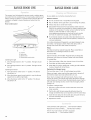
RANGEHOODUSE RAN( EHOODCARE
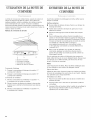
The canopy hood is designed to remove smoke, cooking vapors
and odors from the cooktop area. For best results, start the hood
before cooking and allow it to operate several minutes after the
cooking is complete to clear all smoke and odors from the
kitchen.
Hood control panem
S C D
A. Controls
B.Lightswitch
C.Blowerswitch
D.Blowerspeedcontrolswitch
Operating the light
1. Move the light switch to the "1" position. The light should
turn on.
2. Move the light switch to the "0" position. The light should
turn off.
Operating the blower
1. Move the blower switch to the "1" position. The blower
should turn on.
2. Move the blower speed control switch to vary the blower
speed from low (left) to high (high).
3. Move the blower switch to the "0" position. The blower
should turn off.
_iiiiiiii_i!!i!iii_i:ild!:_iii!il¸%iii_d!ii_,'ii_ii!iii!!i_i:_!!_i!i_iii_i_iihi?_i:i!_
Be sure lights are cool before cIeaning the hood.
Exterior surfaces
[] Do not use steel wool or soap-fiIIed scouring pads.
[] Rub in direction of the grain line to avoid marring the surface.
[] Always wipe dry to avoid water marks.
[] KitchenAid _'Professional Formula Stainless Steel Cleaner &
Polish is the cleaner recommended for cleaning stainless steel
surfaces on this product. To order call our Customer Service
Center at 1-800-442-9991 or order on-line at
www.applianceaccessories.com and ask for part number
8171420. To order from Canada, call 1-800-807-6777.
[] if commercial cleaners are used, follow label directions. Do
not use products that contain chlorine (bleach). Chlorine is a
corrosive substance.
For routine cleaning and fingerprints, use liquid detergent soap
and water, or all-purpose cleaner. Wipe with damp cloth or
sponge, then rinse with clean water and wipe dry.
Filters
The filters should be washed frequently. Place metal filters in
dishwasher or hot detergent solution to clean.
To remove filter:
Use two hands to remove filter. Push tab back to release the
locking pin, pull down and forward. Repeat with other filter(s).
To reinstall filter:
1. Place back edge of filter into channel at rear of hood liner.
2. Push filter up while pushing tab back.
3. When filter is in place, release tab. Locking pin will hold filter
in place. Repeat with other filter(s).
Replacing the halogen lamps
The hood liner uses 12-volt, 20 watt halogen lamp bulbs.
Bdore you begin, make sure that the range hood is turned off
and that the lamps have had sufficient time to cool.
Never touch a halogen bulb with bare hands. Even a small
amount of oil from your hands couId cause the buIb to explode
when it heats up. if you do touch the bulb directly, clean it with a
soft cloth and rubbing alcohol, and let it dr},,thoroughly, before
turning it on.
To replace a halogen lamp:
1. Remove 2 screws from the circular metal trim around the
lamp assembly.
2. PulI the trim with the Iamp assembly attached down far
enough so that the lamp can be pushed out of the socket clips.
3. insert the new lamp into the socket ciips and push the lamp
and trim assembly back up into the hood.
4. Replace the screws
Charcoal Filters (with grates/) kit........Part Number 4396565
Replacement Charcoal Filters........Part Number 4378623
Two 6" (15.2 cm) round to 10" (25.4 cm) round
vent transition kit ........Part Number 4396915
t0

REQUESTINGASSISTANCEORSERVICE
if you need assistance or service in U.S.A.
Call the KitchenAid Customer mnteractionCenter toll=free at
1-800-253-1301o Our consultants are avaiiabie to assist you,
When calling: Please know the purchase date, and the complete
modet and serial number of your appliance This information wilI
hetp us better respond to your request.
Our consultants provide assistance with:
_, Features and specifications on our full Iine of appliances
_, Installation information
_, Use and maintenance procedures
_, Accessory and repair parts sales
_, Specialized customer assistance (Spanish speaking, hearing
impaired, limited vision, etc.)
_, Referrals to Iocal dealers, service companies, and repair parts
distributors
KitchenAid designated service technicians are trained to fulfill the
product warranty and provide after-warranty service, anywhere in
the United States.
To locate the designated service company in your area, you can
also look in your telephone directory Yellow Pages.
If you need replacement parts
If you need to order repIacement parts, we recommend that you
use onty factory-authorized parts. These parts will fit right and
work right, because they are made to the same exacting specifi-
cations used to build every new KitchenAid appliance.
To locate factory-authorized parts in your area, catl our Customer
Interaction Center telephone number, your nearest authorized
service center, or 1-800-442-1111.
For further assistance
If you need further assistance, you can write to KitchenAid with
any questions or concerns at:
Customer Interaction Center
c/o Correspondence Dept.
2000 North M-63
Benton Harbor, MI 49022-2692
Please include a daytime phone number in your correspondence.
if you need assistance or service i_ Canada
For product related questions, please call the KitchenAid Canada
Inc. Customer Interaction Center toil free: 1=800=461=5681
Monday to Friday 8:00 a.m. - 6:00 p.m. (EST).
Saturday 8:30 a.m. - 4:30 p.m. (EST}.
Our consultants provide assistance with:
[] Features and specifications on our full line of appliances.
[] Referrals to local dealers.
For parts, accessories and service in Canada
Call 1-800-807=6777. KitchenAid Canada Inc. designated service
technicians are trained to fulfi!I the product warranty and provide
after-warranty service, anywhere in Canada.
For further assistance
If you need further assistance, you can write to KitchenAid
Canada Inc. with any questions or concerns at:
Customer Interaction Center
KitchenAid Canada, Inc.
1901 Minnesota Court
Mississauga, Ontario L5N 3A7
Please include a daytime phone number in your correspondence.
11

KITCHENAID ®VENTILATION WARRANTY
ONE YEAR LIMITED WARRANTY
For one year from the date of purchase, when this major appliance is operated and maintained according to instructions attached to or
furnished with the product, KitchenAid or KitchenAid Canada (hereafter KitchenAid") will pay for factory specified parts and repair
labor to correct defects in materials or workmanship. Service must be provided by a KitchenAid designated service company.
ITEMS KITCHENAID WILL NOT PAY FOR
1. Service calls to correct the installation of your major appliance, to instruct you how to use your major appliance, to replace or repair
house fuses or to correct house wiring or plumbing.
2. Service calls to repair or replace appliance light bulbs, air filters or water filters. Those consumable parts are excluded from warranty
coverage.
3. Repairs when your major appliance is used for other than normal, single-family household use.
4. Damage resulting from accident, alteration, misuse, abuse, fire, flood, acts of God, improper installation, installation not in
accordance with electrical or plumbing codes, or use of products not approved by KitchenAid.
5. Replacement parts or repair labor costs for units operated outside the United States or Canada.
6. Pickup and delivery. This major appliance is designed to be repaired in the home.
7. Repairs to parts or systems resulting from unauthorized modifications made to the appliance.
8. Expenses for travel and transportation for product service in remote locations.
9. The removal and reinstallation of your appliance if it is installed in an inaccessible location or is not installed in accordance with
published installation instructions.
DISCLAIMER OF IMPLIED WARRANTIES; LIMITATION OF REMEDIES
CUSTOMER'S SOLE AND EXCLUSIVE REMEDY UNDER THIS LIMITED WARRANTY SHALL BE PRODUCT REPAIR AS PROVIDED
HEREIN. IMPLIED WARRANTIES, INCLUDING WARRANTIES OF MERCHANTABILITY OR FITNESS FOR A PARTICULAR PURPOSE,
ARE LIMITED TO ONE YEAR OR THE SHORTEST PERIOD ALLOWED BY LAW. KITCHENAID SHALL NOT BE LIABLE FOR
INCIDENTAL OR CONSEQUENTIAL DAMAGES. SOME STATES AND PROVINCES DO NOT ALLOW THE EXCLUSION OR LIMITATION
OF INCIDENTAL OR CONSEQUENTIAL DAMAGES, OR LIMITATIONS ON THE DURATION OF IMPLIED WARRANTIES OF
MERCHANTABILITY OR FITNESS, SO THESE EXCLUSIONS OR LIMITATIONS MAY NOT APPLY TO YOU. THIS WARRANTY GIVES
YOU SPECIFIC LEGAL RIGHTS AND YOU MAY ALSO HAVE OTHER RIGHTS, WHICH VARY FROM STATE TO STATE OR PROVINCE
TO PROVINCE.
Outside the 50 United States and Canada, this warranty does not apply. Contact your authorized KitchenAid dealer to determine if
another warranty applies.
If you need service, first see the "Troubleshooting" section of the Use & Care Guide. After checking "Troubleshooting," additional help
can be found by checking the "Assistance or Service" section or by calling KitchenAid. In the U.S.A., call 1-800-422-1230. In Canada,
call 1-800-807-6777. 10/05
t2

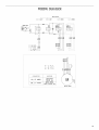
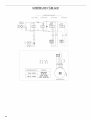
WIRINGDIAGRAM
Slide SM_;che_
I I I I
_0 1 LIOHT Q 0 1 MOT_ I 2 3 5PEEO 1 2 3 SPEEO
i!:
OLK
WHT
io:
BLU
r
i
......................... i
I '
i
i
i
I I '
4-1:1° v
4- 2 : 2° V
4-3:3° V
CAPACITOR VOLTAGE
200-240V
10 _ F 400V 50-60 Hz
25 # F 400V 120V 60Hz
lOOV 50-60 Hz
_J
MOTOR GROUP
13

SI CURITI DELAHOTTEDECUISINII RE
Votre s_curit_ et celle des autres est tr_s importante.
Nous donnons de nombreux messages de securit6 importants dans ce manuel et sur votre appareil menager. Assurez-vous de
toujours life tous les messages de securite et de vous y conformer.
Voici le symbole d'alerte de securite.
Ce symbole d'alerte de securite vous signale les dangers potentiels de deces et de blessures graves a vous
et & d'autres.
Tous les messages de securite suivront le symbole d'alerte de securite et le mot "DANGER" ou
"AVERTISSEMENT'. Ces mots signifient :
Risque possible de deces ou de blessure grave si vous ne
suivez pas immediatement lee instructions.
Risque possible de deces ou de blessure grave si vous
ne euivez pas lee instructions.
Tous lee messages de securite vous diront quel est le danger potentiel et vous disent comment reduire le risque de blessure et
ce qui peut se produire en cas de non-respect des instructions.
t4

IIVIPORTANTES iNSTRUCTiONS DE SECURITE
AVERTISSEMENT : POUR REDUIRE LE RISQUE
D'INCENDE, CHOC ELECTRIQUE OU DOMMAGES
CORPORELS, RESPECTER LES INSTRUCTIONS
SUWANTES :
m Utiliser cet appareiI uniquement dans les applications
envisag_es par Ie fabricant. Pour toute question, contacter
le fabricant.
m Avant d'entreprendre un travail d'entretien ou de nettoyage,
interrompre I'alimentation de la hotte au niveau du tableau
de dis]oncteurs, et verrouiller le tableau de disjoncteurs
pour emp_cher tout retablissement accidenteI de
I'alimentation du circuit. Lorsqu'il n'est pas possible de
verrouiller Ie tableau de dis]oncteurs, placer sur Ie tableau
de dis]oncteurs une etiquette d'avertissement proeminente
interdisant Ie retablissement de I'alimentation.
m Tout travail d'instailation ou c&blage 6lectrique dolt 6tre
realis6 par une personne quaIifiee, dans Ie respect des
prescriptions de tous les codes et normes applicabIes, y
compris les codes du bb.timent et de protection contre les
incendies.
m Une source d'air de debit suffisant est necessaire pour Ie
fonctionnement correct de tout appareil & gaz (combustion
et _vacuation des gaz a combustion par la cheminee), pour
qu'iI n'y ait pas de reflux des gaz de combustion. Respecter
les directives du fabricant de I'6quipement de chauffage et
les prescriptions des normes de s_curite - comme celles
publiees par Ia National Fire Protection Association (NFPA)
et I'American Society for Heating, Refrigeration and Air
Conditioning Engineers (ASHRAE), et les prescriptions des
autorites regIementaires locales.
m Lots d'operations de decoupage et de pergage darts un mur
ou un plafond, veilIer a ne pas endommager Ies cb.blages
electriques ou canaIisations qui peuvent s'y trouver.
m Les systemes d'6vacuation doivent toujours decharger I'air
I'ext6rieur.
MISE EN GARDE : Cet appareiI est conqu uniquement
pour la ventilation gen6rale. Ne pas I'utiliser pour I'extraction
de matieres ou vapeurs dangereuses ou explosives.
MtSE EN GARDE : Pour minimiser le risque d'incendie
et 6vacuer adequatement les gaz, veilIer a acheminer I'air
aspir6 par un conduit jusqu'a I'exterieur - ne pas d6charger
I'air aspire darts un espace vide du b&timent comme une
cavite muraIe, un plafond, un grenier, un vide sanitaire ou
un garage.
AVERTmSSEMENT : POUR RCDUIRE LE RISQUE
D'INCENDE, UTILISER UNIQUEMENT DES CONDUITS
AVERTISSEMENT : POUR MINIMISER LE RISQUE
D'UN FEU DE GRAISSE SUR LA CUISINIERE :
m Ne iamais laisser un _16ment de surface fonctionner &
puissance de chauffage maximale sans surveillance. Un
renversemenb/debordement de matiere graisseuse pourrait
provoquer une inflammation et Ia g6n_,ration de fumee.
Utiliser une puissance de chauffage moyenne ou basse
pour le chauffage d'huile.
m VeilIer a toujours faire fonctionner le ventilateur de la hotte
Iors de la cuisson avec une puissance de chauffage eIev6e
ou lots de Ia cuisson d'un mets a fiamber (a savoir crSpes
Suzette, cerise iubilee, steak au poivre fiambe).
m Nettoyer fr_quemment les ventilateurs d'extraction. VeilIer
ne pas laisser la graisse s'accumuler sur les surfaces du
ventilateur ou des filtres.
m Utiliser toujours un ustensile de tailIe appropriee. Utiliser
touiours un ustensile adapte a la taille de I'_lement
chauffant.
AVERTISSEMENT: POUR REDUIRE LE RISQUE DE
DOMMAGES CORPORELS APRES LE DECLENCHEMENT
D'UN FEU DE GRAISSE SUR LA CUISINIERE, APPLIQUER
LES RECOMMANDATIONS SUIVANTES :a
m Placer sur le recipient un couvercie bien aiust_, une t61e&
biscuits ou un plateau metallique POUR ETOUFFER LES
FLAMMES, p.uis eteindre Ie brOleur b.gaz ou _lectrique.
VEILLER A EVlTER LES BRULURES. Si les fiammes ne
s'eteignent pas imm_diatement, EVACUER LA PIECE ET
APPELER LES POMHERS.
m NE JAMAIS PRENDRE EN MAIN UN RECIPIENT
ENFLAMME - vous risquez de vous brOter.
m NE PAS UTILISER D'EAU, ni un torchon humide - ceci
pourrait provoquer une explosion de vapeur brOlante.
m Utiliser un extincteur SEULEMENT si :
- II s'agit d'un extincteur de classe ABC, dont on connait le
fonctionnement.
- II s'agit d'un petit feu encore limite b.I'endroit ou il s'est
declar&
- Les pompiers ont et_ contactes.
- II est possible de garder Ie dos oriente vers une sortie
pendant I'operation de Iutte contre le feu.
aRecommandations tirees des conseils de securite en cas
d'incendie de cuisine publies par la NFPA.
m AVERT_SSE_ENT : Pour r_duire le risque d'incendie
ou de choc electrique, ne pas utiliser ce ventilateur avec un
queiconque dispositif de reglage de la vitesse a semi-
conducteurs.
CONSERVEZ CES INSTRUCT ONS
15

EXIGENCESD'INSTALLATION
Rassembler les outils et pi_ces necessaires avant de commencer
Hnstaflation. Ure et suivre les instructions foumies avec les outils
indiqu_s ici.
Outillage n_cessaire :
Im niveau
_, perceuse avec forets de 1W' (3 cm) et %2 (6 mm),
crayon
pince a denuder ou couteau utilitaire
m_tre-ruban ou r_gle
pince
pistolet de calfeutrage et compose de caifeutrage r_sistant
I'eau
ruban adh_sif pour conduits
scie sauteuse ou scie a guichet
tournevis a lame plate
cisaille de ferblantier
tournevis Phillips
Pi_ces n_cessaires :
_, Serre-c_ble 3/4"(19,0 ram) (homologation UL ou CSA)
cable d'alimentation electrique
circuit d'evacuation metallique
iMPORTANT : Observer les dispositions de tous Ies codes et
r_glements en vigueur=
InstalIer Ia hotte d'extraction a distance de toute zone exposee
des courants d'air, comma fen6tres, portes et bouches de
chauffage=
Respecter Ies dimensions indiquees pour Ies ouvertures
d6couper dans Ies placards. Les dimensions indiqu_es prennent
en compte les valeurs minimales des degagements de separation
necessaires.
NOTE : Insta!ler la doublure de hotte dans une enceinte
personnalisee=
L'espace entre Ia table de cuisson et ta hotte dependra du
mat_riau utilise par le constructeur pour Ia doublur
On doit disposer d'une prise de courant 6Iectrique reliee a la
terre=Voir Ia section "Specifications electriques"=
On recommande de fixer la hotte sur du bois massif.
La hotte d'extraction a _te configuree a Pusine pour Ia decharge
travers Ie toit ou a travers lemur=
On devra assurer I'etancheite de toutes Ies ouvertures (plafond
et mur) d&coupees pour Hnstailation de la hotte.
Espacements d'instaHation
largeur minimale de I'espace d'installation entre les placards :
module 36" (91 4 cm), 36" (91,4 cm)
module 48" (121,9) 48" (121,9 cm)
le support de la hotte dolt _tre J_......
capable de soutenir une charge de
/
40 Ib (18,1 kg) pour le module de distance fibre
36" (91,4 cm), ou de 55 Ib (25 kg) recommand6e de 24"
pour le modele 48" (121,9 cm) 36" (61,0 cm a 91,4 cm)
entre la table de cuisson
et la hotte
largeur/profondeur
de la doublure de
hotte : 22" (55,9 cm)
t6

/
/
/

[] Pour Ie mod61e de 36" (91,4 cm), on dolt utiliser un circuit
d'evacuation en conduit fond de diam6tre 6" (15,2 cm). Pour
le mod6Ie de 48" (121,9 cm), on doit utiliser deux circuits
d'6vacuation en conduit fond de diam6tre 6" (15,2 cm), ou un
unique circuit d'evacuation en conduit rond de diametre 10"
(25,4 cm) et un raccord de transition n° 4396915.
[] Le circuit d'evacuation de I'air doit se terminer & I'exterieur.
[] Ne pas terminer Ie circuit d'evacuation dans un espace ferme
(grenier ou autre).
[] Ne pas utiliser une bouche de d6charge murale de 4"
(10,2 cm), du type utilise pour un appareiI de buanderie.
[] Utiliser uniquement du conduit m6tallique. On recommande
I'emploi de conduit rigide. Ne pas utiliser de conduit de
plastique ou de metal tr6s mince.
Pour obtenir un fonctionnement efficace et silencieux :
[] Utiliser autant que possible des sections droites et minimiser
le nombre de coudes.
[] Ne pas utiliser plus de trois coudes a 90°.
[] VeilJerace qu'iI y ait une section droite de conduit de 24"
(61 cm) ou plus entre deux coudes, si on dolt utiliser plus de
un raccord coud&
[] Ne pas connecter ensemble deux raccords coudes.
[] Assurer I'6tanch6it6 de chaque jointure du circuit d'6vaeuation
avec du ruban adh6sif pour conduit.
[] Utiliser un caIfeutrant pour assurer I'6tancheit6 autour de la
bouche de decharge a I'ext6rieur, entre le conduit et
I'ouverture a travers Ie toit ou lemur.
Installation darts une r_gion _ cmimat froid
II convient d'installer un clapet anti-reflux additionnel pour
minimiser Ies reflux d'air froid, et d'installer au sein du circuit
d'evacuation un materiau non metallique (isolant thermique) pour
minimiser Ia conduction de chaleur entre I'exterieur et Hnterieur
de la maison. Par rapport a HsoJant thermique, Ie dapet anti-
reflux devrait 6tre situ6 du c6te froid.
L'isolant thermique doit 6tre place aussi pr6s que possible de
I'endroit ou le circuit d'evacuation pen6tre dans la partie chauffee
de la maison.
Air d"appoint
Le code du b&timent local peut exiger I'utilisation d'un syst6me
d'introduction d'air d'appoint darts le cas ou la capacit6
d'extraction (pieds cubes d'air par minute) de Ia hotte est
sup&rieure a une vabur specifiee. La valeur specifi_e (debit d'air,
en pieds cubes par minute) est variable d'une juridiction a une
autre. Pour determiner Ies exigences specifiques, consulter un
professionnel local des installations de chauffage et climatisation.
M_thodes d'_vacuation
La hotte d'extraction a &t6 configur&e a I'usine pour la decharge
travers le toit ou a travers Iemur.
Pour le mod61e de 36" (91,4 cm), on dolt utiliser un circuit
d'evacuation en conduit fond de diam6tre 6" (15,2 cm). Pour b
mod6Ie de 48" (121,9 cm), on doit utiliser deux circuits
d'&vacuation en conduit fond de diam6tre 6" (15,2 cm), ou un
unique circuit d'evacuation en conduit fond de diametre 10"
(25,4 cm). La hotte comporte une ouverture de sortie de
diam6tre 6" (15,2 cm).
NOTI: : On deconseilb I'emptoi d'un conduit fiexibb. Un conduit
flexible peut susciter une retro-pression et des turbulences de
I'air, ce qui reduit considerabtement la performance.
La sortie a I'exterieur du circuit d'evacuation peut se faire
travers le toit ou a travers un mur. Pour Iasortie a travers un mur,
on dolt empJoyer un raccord coude a 90°.
Pour une installation avec recycJage, veiller ace que I'air aspir&
par Ia hotte soit decharge dans la cuisine et non pas dans une
cavite ferm6e - murs, plafonds, greniers, vides sanitaires ou
garages.
decharge a
travers le toit
bouche de
d@harge
murale
7
decharge a
travers le mur
Ca_cul de ta _ongueur effective du circuit
d'_vacuation
Pour calculer Ja Iongueur effective du circuit d'evacuation
necessaire, additionner bs Iongueurs equivalentes (pieds/m6tres)
de tous bs composants utilises dans le syst6me.
La Iongueur equivabnte du circuit ne doit pas depasser 35 pieds
(10,7 m6tres) pour un circuit d'evacuation en conduit de diam6tre
6" (15,2 cm), ou 60 pieds (18,3 metres) pour un circuit
d'evacuation en conduit de diam6tre 10" (25,4 cm).
Composant du circuit Conduit rond dia. 6" (15,2 cm)
ou dia. 10" (25,4 cm)
Coude _45° 2,5 pi
(0,sm)
Coude _90°
5,0 pi
(! ,5 m)
bouche de
d@harge murale
Coude a 90° I_<-_ 6 pi (1,8 m) _----}_1
_x_ --_ Exemple
(" I I !hJ de circuit
_-[_ d evacuation
2pi I I 1 coude a 90° = 5 pi (1,5 m)
(06m)
_l I section droite de 8 pi (2,4 m) = 8 pi (2,4 m)
p-_ 1 bouche de d_charge murale = 0 pi (0 m)
H
L_ Longueur equivatente totale
du syst6me =13 pi (3,9 m)
t8

Risquedechocelectrique
D_connecter la source de courant 61ectrique avant
Fentretien,
Replacer pieces et panneau× avant de Mire la remise
en marche°
Le non-respect de ces instructions peut causer
un decec ou un choc electriqueo
iMPORTANT : La hotte doit _tre correctement reli6e a Ia terre en
conformite avec Ies codes et r_glements Iocaux en vigueur, ou en
I'absence d'un tel code, ccnformement aux prescriptions de la
plus resente edition du National Electrical Code, ANSI/NFPA 70,
ou du Code canadien des installations electriques, CSA C22.1.
Si les codes en vigueur le permettent et si on utilse un
conducteur distinct de liaison a la terre, / est recommand_ qu'un
electricien qualfie verifie la qualte de la faiscn a la terre.
Pour obtenir un exemplaire des codes menticnnes ci-dessus,
contacter :
National Fire Protection Association
One Batterymarch Park, Quincy, MA 02269
CSA International
8501 East Pleasant Valley Road
Cleveland, Ohio 44131-5575
[] L'apparel doit _tre almcnte par un circuit de 120 V,60 Hz,
CA seulement, 15 amperes, proteg6 par fusible. On
recommande egalement d'utilser un fusible ou un disjoncteur
temporis& II est recommande d'almenter Ia hotte par un
circuit distinct qui n'afmente que cet appareiL
[] Ne pas ut/iser une tuyauterie de gaz pour le raccordement
la terre.
[] En cas de doute quanta Ia qualit6 de Ia liaison a Ia terre de la
hotte, consulter un electricicn qualfi&
[] Ne pas installer un fusible darts le conducteur neutre ou darts
le conducteur de liaison a Ia terre.
[] La hotte doit _tre raccord6e au reseau 61ectrique uniquement
avec des conducteurs de cuivre.
[] La hotte doit &tie. raccordee directement au coupe-circuit
avec fusible ou au disjoncteur par I'interm6diaire d'un cgble &
conducteurs de cuivre, a bfndage metalique flexible ou
gaine non-metalique.
[] Un serre-c&ble (homologaticn UL ou CSA) dcit _tre insta/e
chaque extremit6 du c_ble d'almentation. Le calbre des
conducteurs (cuivre seulement) et les connexions dcivent _tre
compatibles avec la demande de courant de I'apparel
specifiee sur Ia plaque signal&tique.
[] La ta/Ie des conducteurs dolt satisfaire aux prescriptions de
la plus reccnte edition du National Electrical Code,
ANSI/NFPA 70, cu du Code canadien des instalations
elcctriques, normes CSA C22.1-94 et C22.2 n° 0-M91, et aux
prescriptions de tousles codes et r6glements Iocaux en
vigueur.
19

INSTRUCTIONSD'INSTALLATION
[]
Placer un epais materiau de protection sur le plan de travail et
la table de cuisson, pour la protection contre des dommages
et contre Ies souillures.
Si on doit utiliser I'opercule arrachable du sommet, percer
un trou de 11/4"(3 cm) dans le support de hotte
I'emplacement indique.
cm)
Risque du poide excessif
UtHiser deux ou plus de pereonnee pour deplacer et
installer la hotte de la cuisiniere.
Le non-respect de cette instruction peut causer
une Nessure au dos ou d'autre blessure.
Marquer sur le support de la hotte I'empiacement des quatre
trous de 7/32" (6 mm) - voir I'illustration.
23_"
17a/_6'
tafltede la hotte A B
36" (91,4 cm) 317/16"(79,9 cm) 1523/_'' (39,9 cm)
_8" (121,9 cm) 437/16'' (110,3 cm) 212%_" (55,2 cm)
2. Percer les quatre trous.
3. Realiser une ouverture rectangulaire pour le carter du moteur
du ventilateur.
i , i ,z,
i °
m
I o
tai/tede/a hotte A B C
36" (91,4 cm) 28" (71,1 cm) 14" (35,5 cm) 16" (40,6 cm)
48" (121,9 cm) 36" (91,4 cm) 18" (45,7 cm) 14½ (36,8 cm)
4. [] Si on doit utiliser I'opercule attachable arri6re, percer un
trou de 11/4"(3 cm) darts lemur/_ l'emplacement indiqu_.
support de la hotte axe central I I
(rue avant) de la hotte i_i------A_i __
I ,2, 2"(5,1ore)
tail/e de la hefts A ,
36" (91,4 cm) 143/1e'' (36,0 cm)
48" (121,9 cm) 201/4'' (51,4 cm)
2O
Oter les filtres (utiliser Ies deux mains). Pousser la patte vers
I'arri_re pour Iiberer Ia broche de verrouillage; tirer vers le bas
et vers I'avant. Conserver Ie filtre a part. Repeter ces
operations pour chaque autre filtre.
\
\,
6. Oter le couvercle du boitier de connexion, derri6re le filtre de
droite.
7. Installer un serre-c_ble (homologation UL ou CSA) sur Ia
doublure de hotte - veiller ace qu'il soit possible de serrer
les vis.
Risque de choc 61ectrique
Deconnecter la source de courant electrique avant
_'entretien.
Replacer pieces et panneaux avant de faire la remiss
en marche.
Le non-respect de ces instructions peut causer
un decks ou un choc e_ectrique.
1. D&connecter la source de courant electrique.
2. Placer un c_ble d'alimentation iusqu'au bo_tier de connexion
de la botts - respecter les prescriptions du Code national de
I'electricit6 ou de Ia norme CSA en vigueur, ou des codes et
r_glements Iocaux en vigueur. IIfaut que Ia Iongueur des
conducteurs soit suffisante pour qu'il soit possible de r&aliser
la liaison entre Ietableau de distribution et Ia hotte, et Ies
connexions dans la boke de connexion de la hotte.
3. Trouver Ies quatre vis de montage dans Ie sachet de pieces.
On recommande de placer Ies vis a proximite des trous sur la
doublure de hotte pour pouvoir y acceder faciIement.
La page est en cours de chargement...
La page est en cours de chargement...
La page est en cours de chargement...
La page est en cours de chargement...
La page est en cours de chargement...
La page est en cours de chargement...
La page est en cours de chargement...
La page est en cours de chargement...
-
 1
1
-
 2
2
-
 3
3
-
 4
4
-
 5
5
-
 6
6
-
 7
7
-
 8
8
-
 9
9
-
 10
10
-
 11
11
-
 12
12
-
 13
13
-
 14
14
-
 15
15
-
 16
16
-
 17
17
-
 18
18
-
 19
19
-
 20
20
-
 21
21
-
 22
22
-
 23
23
-
 24
24
-
 25
25
-
 26
26
-
 27
27
-
 28
28


KitchenAid KHVU761RSS1 Le manuel du propriétaire
- Catégorie
- Hottes
- Taper
- Le manuel du propriétaire
- Ce manuel convient également à
dans d''autres langues
Documents connexes
-
KitchenAid KWCU320WSS0 Le manuel du propriétaire
-
-
-
-
-
KitchenAid KWCU360JSS1 Le manuel du propriétaire
-
-
-