GE GDWF100R30WW Guide d'installation
- Catégorie
- Lave-vaisselle
- Taper
- Guide d'installation

04 _,Mf
Appliances
Installation Instructions
Built-In Dishwasher
If you have questions, call 800.GE.CARES(800.432.2737) or visit our Website at: GEAppliances.com
In Canada call 1.800.561.3344 or www.GEAppliances.ca
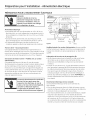
BEFORE YOU BEGIN
Readthese instructions completely and
carefully.
| L J l"_t'_ _'T'A k |'It
I Ivli_Ui_ | _l_l| - The dishwasherMUST
be installedtoallowforfutureremovalfromtheenclosure
if service is required.
IM PORTANT Observeallgoverning codesand
ordinances.
• Note to Installer - Besure to leave these instructions for the
consumer's and local inspector's use.
• Note to Consumer - Keep these instructions with your
Owner's Manual for future reference.
• Skill Level- Installation of this dishwasher requires
basic mechanical, electrical and plumbing skills. Proper
installation is the responsibility of the installer. Product
failure due to improper installation is not covered under
the GEAppliance Warranty. Seewarranty information.
• Completion Time - 1 to 3 Hours. New installations require
more time than replacement installations.
If you received a damaged dishwasher, you should
immediately contact your dealer or builder.
Optional Accessories - See the Owner's Manual for available
custom panel kits.
FOR YOUR SAFETY
Read and observe all CAUTIONSand WARNINGS
shown throughout these instructions, While performing
installations described in this booklet, gloves and either
safety glasses or goggles should be worn,
READ CAREFULLY.
KEEP THESE INSTRUCTIONS.
Stainless SteelTub Models
imagination at work

Installation Preparation
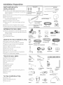
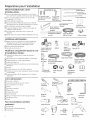
PARTS SUPPLIED WITH
INSTALLATION KIT:
[] Two #8-18 x 5/8" Phillips special head screws, to
secure dishwasher to underside of countertop or
sides of cabinets.
[] Junction box cover and #!0-1/2" hex-head screw
[] Side and top trim
[] Trim Panel Accessorg Kit (not shown)
(Custom panel models onlg)
[] Sound upgrade kit (some models)
[] Drain hose (78"), drain hose hanger and hose
clamp
[] Literature, product samples and/or coupons
[] Hard water test strip (Models with Bulk Dispenser)
Screw Kit
??
#8 Phillips
Special Head Screws
5/8" long
?
#10 Hex-Head
J-Box Screw
1/2" long
_ound Upgrade Kit
{Some Models)
tl Hard Water Test Strip
J(Models with
Bulk Dispenser)
Side Trim
Side Trim
Top Trim
Trim Pieces
Drain Hose Hanger
Drain Hose (78")
Q
Junction
Box Cover
Hose Clamp
MATERIALS YOU WILL NEED:
[] Ferrule, compression nut and 90° Elbow (5/8" NPT
external thread on one end, opposite end sized to
fit water supplg)
[] Thread seal tape
[] UL-listed wire nuts (3)
Materials For New Installations Only:
[] Air gap for drain hose, if required
[] Waste tee for house plumbing, if applicable
[] Electrical cable or power cord, if applicable
[] Screw-tgpe hose clamps
[] Strain relief for electrical connection
[] Hand shut-off valve
[] Water line 5/8" min. copper
[] Coupler for extending drain line, if applicable
[] GPF10L!0' drain hose, if needed
90° Elbow, Hand Thread Wire Nuts (3)
Ferrule and Shut-Off Seal Tape
Compression Nut Valve
Waste Tee
_ Air
Gap
Hot Water Line
Electrical Cable
(or Power Cord, if applicable)
GPF20L
20' Drain Hose
Screw-Tgpe Strain Relief Coupler
Hose Clumps
TOOLS YOU WILL NEED:
[] Phillips-head screwdriver
[] !/4" and 5/16" nutdriver
[] 6" Adjustable wrench
[] Level
[] Carpenter's square
[] Measuring tape
[] Safetg glasses
[] Flashlight
[] Bucket to catch water when flushing the line
[] !5/16" socket
[] Gloves
For New Installations Only:
[] Tubing cutter
[] Drill and appropriate bits
[] Holesaw set
2
Head
Screwdriver
114"and
15116" Socket
Flashlight
Gloves
5/16" Nutdriver
Level
6" Adjustable Tubing Cutter
Wrench Carpenter's
Safetg Glasses Measuring Tape
Bucket Hole Saw Set Drill and Bits

Installation Preparation-Enclosure
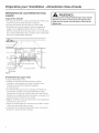
PREPARE DISHWASHER ENCLOSURE
To reducethe riskofshock,fire,orinjurg
topersons,the installermust ensurethat
thedishwasheriscompletelgenclosedat
thetimeofinstallation.
Pare reducir el riesgo de choque, incendio
o lesi6n a personas, el instalador se
debe cerciorar de que la lavadora est_
completamente cerrada en elmomento
de lainstalaci6n.
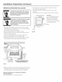
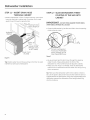
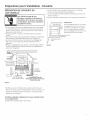
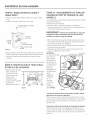
•The rough cabinet opening must have a minimum width
and depth of 24" and height of ]4-1/2" _+1/4" from the floor
to the underside of the countertop.
• The back wall should be free of pipes or wires.
Adjacent cabinets should be square and plumb to ensure
a good fit. Refer to Figure A
For a corner installation, allow 2" minimum clearance
between the dishwasher and the adjacent wall.
Provide at least 28-5/8" infront of the dishwasher to allow
the dishwasher door to open fully. Referto Figure B
• The dishwasher must be installed no more than 10 feet
from sink for proper drainage.
The dishwasher must be fullg enclosed on the top, sides
and back.
The dishwasher must not support any part of the enclosure.
[
Countertop
Dishwasher
2" Minimum
Clearances:
In a corner installation, provide at
least 2" clearance between the
dishwasher and the adjacent
cabinet, wall, or other appliance.
Provide at least 28-3/8" of clearance
in front of the dishwasher.
28-3/8" Minimum
Figure B
34-1/2" + 1/4"
Underside of
Countertop
to Floor
Figure A
Floor MUST
be Evenwith
Room Floor
J 24" Min:
Squore
ond
Plumb
Plumbing and Electric Service
Must Enter Shaded Area
• Moke sure the floor is level inside the opening and even with
the finished floor of the kitchen. This will facilitate removal
of the dishwasher at a later date for service, if needed.
Special consideration for a dishwasher installed on
a elevated platform
The elevated platform must be flat and level.

InstallationPreparation-Drain
PREPARE DRAIN PLUMBING
Drain Requirements
• Drain hose must not exceed 10 feet in length.
• A high drain loop or air gap is required. See below.
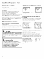
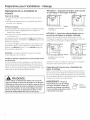
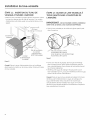
Drain Method
The tgpe of drain installation depends on the following:
• Do local codes or ordinances require an air gap?
• Iswaste tee less than 18" above the floor?
If the answer to either question is yes, an air gap must be used.
Referto Method 1 (Figure C)in the adjacent illustrations.
If both answers are no, either an air gap or high drain loop mag
be used. Refer to Method 1 (Figure C)or Method 2 (Figure D)
in the adjacent illustrations
NOTE: Drain hose elevation must not exceed 48".
Special consideration for a dishwasher installed on
a elevated platform
Ifthe dishwasher isinstalled on an elevated platform, a high
drain loop of at least 32" above the platform must be provided
in addition to the air gap or drain loop requirement determined
above. This is necessmrgfor proper drain performance.
CAUTION
An air gap MUSTBEUSEDif the drain hose is connected to
waste tee or disposer lower than 18" above the floor level.
Failure to provide the proper drain connection height with
an air gap or 32" minimum, high drain loop will result in
improper draining of the dishwasher, which may cause
damage.
PRECAUCION
SEDEBEUSARun espacio de aire si la manguera
de drenaje se conecta a la Tde desechos o al triturador
menos de 18" por encima del nivel del piso. No disponer
la altura correcta de la cone×i6n del drenaje con
un espacio de aire o 32" de minimo, una curva alta
de drenaje resultar_ en un drenaje incorrecto
de la lavadora, Io que pude causar da6os.
METHOD 1-Air Gap with Waste Tee or Disposer
Figure C
Waste TeeInstallation
Disposer Installation
METHOD 2-High Drain Loop with Waste Tee
or Disposer
Usethe drain hose hanger included in the installation kit to
attach the drain hose to the underside of the countertop.
Attachment will be made in a later step.
_ Figure D
Waste Tee Installation
in.
DisposerInstallation
Install waste tee or disposer and the air gap according to the
manufacturer's instructions.
Cabinet Preparation for drain line
Drill a 1-1/2" diameter hole in the cabinet wall within the
shaded area shown in Figure A for the drain hose. Make
sure there are no sharp edges. The drain hose will be passed
through this hole and connected to the drain in a later step.
IMPORTANT-when
connecting the drain line to a
disposer, check to be sure that
drain plug has been removed.
Dishwasher will not drain if
plug is left in place.
_ Remove
Drain
Plug

Installation Preparation-Electrical Supplg
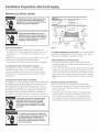
PREPARE ELECTRICAL WIRING
FOR PERSONALSAFETY: Remove house fuse
or open circuit breaker before beginning
installation. Do not use an extension cord or
adapter plug with this appliance.
PARASEGURIDAD PERSONAL: Retire el
fusible de la casa o abra el interruptor de
circuitos antes de empezar la instalaci6n.
No use un cable de extensi6n o enchufe
adaptador con este aparato.
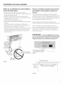
Electrical Requirements
• This appliance must be supplied with 120V,60Hz., and
connected to an individual properlg grounded branch circuit
protected bg a 15- or 20-ampere circuit breaker or time-
delag fuse.
• Wiring must be 2 wire with ground and rated for 75°C(176°F).
• If the electrical supplg does not meet the above
requirements, call a licensed electrician before proceeding.
Grounding Instructions-Permanent Connection
This appliance must be connected to a grounded-metal,
permanent wiring sgstem, or an equipment-grounding
conductor must be run with the circuit conductors and be
connected to the equipment-grounding terminal or lead on
the appliance.
Grounding Instructions-Power Cord Hodels
This appliance must be grounded. Inthe event of a malfunction
or breakdown, grounding will reduce the risk of electric shock
by providing a path of least resistance for electric current.
This appliance is equipped with a cord having an equipment-
grounding conductor and a grounding plug. The plug must
be plugged into an appropriate outlet that is installed and
grounded in accordance with all local codes and ordinances.
_The improper connection of the equipment
grounding conductor can result in a risk
of electric shock. Check with a qualified
electrician or service representative if gou
are in doubt that the appliance is properlg
grounded.
/ I
/ I
I I
Alternate q',
I \
Receptacle , \
Location
1-1/2" Dia.
Hole (Max.)
Location
Area
3" from
Cabinet
Figure E White
For models equipped with power cord: Do not modifg the plug
provided with the appliance; if it will not fit the outlet, have a
proper outlet installed by a qualified technician.
Cabinet Preparation and Wire Routing
• The wiring mag enter the opening from either side, rear
or the floor within the shaded area dimensioned in Figure A
and illustrated above.
Cut a !-!/2" max. diameter hole to admit the electrical cable.
Cable direct connections mag pass through the same hole
as the drain hose and hot water line, if convenient. If cabinet
wall ismetal, the hole edge must be covered with a bushing.
Note: Power cords with plug must pass through a separate
hole.
Electrical Connection to Dishwasher
Electrical connection is on the right front of dishwasher.
Forcable direct connections the cable must be routed as
shown in Figure E.Cable must extend a minimum of 24"
from the rear wall.
Forpower cord connections, install a ]-prong grounding
tgpe receptacle inthe adjacent cabinet rear wall, 6" min.
or 18" max. from the opening, 6" to 18" above the floor.
The receptacle must be accessible and therefore cannot
be installed in the back wall of the dishwasher enclosure.
La conexi6n incorrecta del conductor de
conexi6n a tierra del equipo puede resultar
en choque el6ctrico. Consulte con un
electricista calificado o representante
de servicio si tiene dudas de la conexi6n
a tierra del aparato.
5

Installation Preparation-Hot Water Supply
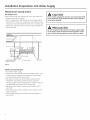
PREPARE HOT WATER SUPPLY
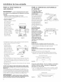
Hot Water Line
• The line meg enter from either side, rear or floor within the
shaded area shown in Figure F.
• The line meg pass through the same hole as the electrical
cable and drain hose, or an additional 1-!/2" diameter hole
meg be cut to accommodate the water line. If a power cord
with plug is used, the water line must not pass through the
power cord hole.
/
/ I
I
I
_1-1/2" Oi,
Hole
ii Shut-off7
Valve Y
Hot_ i:::::::::: ,%.:',::',:':
P.
:: L.
_2"
From
Cabinet
CabinetFace_,-
I__.!9" From Wall
2" From Floor
=_
I \
\
I \
I \
I \
Figure F
CAUTION
The hot water supplg line pressure must be at least 20 PSI.
Lower pressures could cause the water valve to leak and
cause water damage.
PRECAUCI6N
La linea de presi6n del suministro de ague caliente debe
ser al menos 20 PSI.Presiones inferiores podrian causer
que la v61vula del ague gotee g causer da_os por ague.
Water Line Connection
• Turn offthe water supplg.
• Install a hand shut-off valve in an accessible location, such
as under the sink. (Optional, but stronglg recommended
and meg be required bg local codes.)
• The water connection is on the bottom-left side of the
dishwasher. Install the hot water inlet line, using 3/8"
or larger copper tubing. Route the line as shown in Figure F
and extend forward at least 19"from rear wall.
• Adjust the water heater to deliver water between 120°F
and !50°F.
• Flush water line to clean out debris. Use a bucket to catch
water and debris.
• The hot water supplg line pressure must be between 20
and 120 PSI.

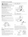
Dishwasher Installation
CAUTION
Do not remove the wood base until you are ready to
install the dishwasher. The dishwasher will tip over
when the door isopened if the base is removed.
PRECAUCION
No retire la base de madera hasta que est_ listo para
instalar la lavadora de platos. Cuando la puerta se abra,
la lavadora de platos se inclinar6 si la base se retira.
STEP 1 - LOCATE INSTALLATION ITEMS
• Locate the items in the installation package and set aside for
use in the listed steps.
• Trim pieces - Step 2
Junction box cover - Step 7 or Step 18
Drain hose and clamp - Step 10
Screw Kit - Step 15
Drain hose hanger - Step 17
Owner's Manual - Step 19 and Step 24
Hard Water test strip - Step 21
Sound upgrade kit (selected models) - Step 22
Product samples and/or coupons - Step 24
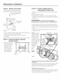
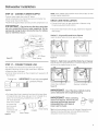
Tgpe 1 - One-hole cable
Adjust tension bg moving spring hook to one of the three holes
on the tub leg.
!INCREASE
DECREASE
One Hole
Figure H
Tgpe 2 - Three-hole cable
Adjust tension bg moving spring hook to one of the three holes
on the pulley cable.
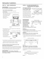
STEP 2 - INSTALL TRIM PIECES
Inthis step, gou will need the trim pieces set aside in Step 1.
Presstop trim piece onto top of tub flange. Start with the
right edge and work gour wag to the left.
Repeat process with the left and right trim pieces working
from the top down.
Open and close the door to check that trim does not bind
and does not interfere with door latch or door hinges.
TrimStrip
Trim -
Strip
Figure G
STEP 3 - CHECK DOOR BALANCE
• With dishwasher on the wood skid,check the door balance
bg opening and closing the door.
If the door drops when released, increase the spring tension.
If the door rises when released, decrease the tension.
There are two tgpes of counterbalance and therefore two
methods of adjustment. Identifg which counterbalance is
present and adjust tension accordinglg. Pleasenote: If there
are 3 holes on the cable, use the cable to adjust; if there is
one hole on cable, use the tub leg to adjust.
Decrease
Figure I
Increase
Tension
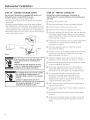
After adjusting spring tension, open and close the door to
make sure the door operates smoothlg. If the door is hard
to move or if the spring cable binds, check the routing of
the spring cable. The cable should be routed between the
shoulders of the pulleg cable roller. If the cable isoff the roller:
latch door, remove spring tension and route the cable between
the shoulders of the roller.See FigureJ.
Pulle__
Shoulder
Correct Spring
Figure J
Cable Routing
IncorrectSpring
CableRouting 7

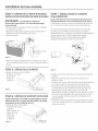
Dishwasher Installation
STEP 4 - REMOVE WOOD BASE,
INSTALL LEVELING LEGS
IMPORTANT- Donotkickoffwoodbase!Damage
will occur.
. Move the dishwasher close to the installation location and lag
it on its back.
• Remove the four leveling legs on the underside of the wood
base with an adjustable wrench or 15/!6" socket.
• Discard base.
)rox.
Figure K
. Screw leveling legs back into the dishwasher frame
approximatelg !/8" from frame as shown.
STEP 5 - REMOVE TOEKICK
• Removethe 2 toekick screws
and toekick.
Set aside
for use in
Step 23.
_,emove 2
Figure L Toekick Screws
STEP 6 - REMOVE TOEKICK BRACE
Skip this step if your model does not have a sound upgrade
kit. If your model does have a sound upgrade kit, this brace
must be removed.
• Remove the 2 toekick brace
screws and
toekick brace.
Discard brace
and set
screws aside
for use in
Step 22.
Figure M
;emove 2
Toekick Screws
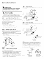
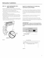
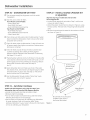
STEP 7 - INSTALL POWER CORD
Skip this step if dishwasher will be permanentlg connected
to the house electrical sgstem.
In this step gou will need the junction box cover and the
#!0 x !/2" hex-head screw from the screw kit set aside in
Step i.
The power cord and connections must complg with the
National Electrical Code, Section/422 and/or local codes and
ordinances. Maximum power cord length is6 feet. Power Cord
Kit wxogx70910, available for purchase from an authorized
GEAppliance Dealer, meets these requirements.
Figure N
Ground
• Install strain relief injunction box bracket.
• Insert power cord through strain relief and tighten.
Make sure black, white and green dishwasher wires are
threaded through small hole injunction box bracket.
Connect like-colored dishwasher and power cord wires. If
power cord wires are not color-coded, connect the ribbed
power cord wire to the white dishwasher wire, the smooth
power cord wire to the black dishwasher wire and the ground
to the green dishwasher wire. Use UL-listed wire nuts of
appropriate size.
Install junction box cover set aside in Step 1, using #!0 hex-
head screw. Besure wires are not pinched under the cover.

Dishwasher Installation
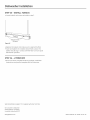
STEP 8 - INSTALL 90 ° ELBOW
• Wrap 90° elbow with thread seal tape.
• Install a 90° elbow onto the water valve.
Front of Dishwasher
90°
Elbow
Figure 0
Water Valve
Bracket
I Hose
Thread
Seal Tape
• Do not overtighten the 90° elbow; water valve bracket could
bend or water valve fitting could break.
Position the end of the elbow to face the rear of the
dishwasher.
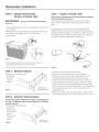
STEP 9 - POSITION WATER LINE AND
HOUSE WIRING
• Position water supply
line and house wiring
on the floor of the
enclosure to avoid
interference with
base of dishwasher
and components
under dishwasher.
Figure P
STEP I0 - INSTALL DRAIN HOSE TO
DISHWASHER DRAIN PORT
In this step you will need the drain hose and clamp set aside
in Step 1.
Stand dishwasher upright.
• Place drain hose clamp over 1-5/16" inside diameter end
of drain hose with the clamp screw positioned on the bottom
of the hose.
IMPORTANT- Prevent drain hose damage and
possible leaks. Be careful not to nick or cut the drain hose.
Push the end of the drain hose over the drain pump outlet
being careful not to disturb the check valve. Refer to Figure q).
Seat the drain hose end against the hose stops on the pump
outlet.
Position hose clamp against the front lip of the drain hose
and tighten clamp.
NOTE:Drain hose
supplied with dish-
washer isapproxi-
mately 78" long.
Ifa longer hose is
needed, a 120" long
hose (!0 feet) may
be purchased from
an authorized
GEappliance
dealer.The
!0' long
hose is
port
number
GPFIOL.
Figure Q
PumpOutlet HoseStop
\
Tip: Avoid unnecessarg service charges. Make a leak free
connection
Insert hose against stop on pump. Position clamp against front
lip of drain hose with clamp screw on bottom side of hose.
Tighten clamp to at least !5 inch-pounds of torque.
Tip: Reduce drain pump noise
Position drain hose clamp so screw is on the bottom side of the
hose. This will prevent noise caused by the clamp coming in
contact with the tub bottom. Refer to Figure q).

Dishwasher Installation
STEP 11 - INSERT DRAIN HOSE
THROUGH CABINET
• Position dishwasher in front of cabinet opening. Insert drain
hose into the hole in cabinet side. If a power cord is used,
guide the end through a separate hole.
Drain
Hose Length 10'
Blanket
Hose
/
House Wiring
(If Power Cord
is NOT Used)
Power Cord
(If Used)
Figure R
Tip: Position water line and house wiring on the floor to avoid
interference with base of dishwasher.
STEP 12 - SLIDE DISHWASHER THREE-
FOURTHS OF THE WAY INTO
CABINET
IM _UK i_l_l|- DO NOT PUSH AGAINST FRONT PANEL
WITH KNEES.DAMAGE WILL OCCUR.
',Grasp the dishwasher bg its sides and slide it into the opening
a few inches at a time.
o Not Push Against
Front Door Panel With
Knee. Damage to The
Door Panel Will Occur.
Figure S
• As gou proceed, pull the drain hose through the opening
under the sink. Stop pushing when the front of the
dishwasher isa few inches forward of adjacent cabinets.
• Make sure drain hose isnot kinked under the dishwasher
and there is no interference with the water line,wiring or ang
other component.
Tip: Make sure the dishwasher will fit in the cabinet. Check to
be sure the power cable, drain hose and hot water line are not
trapped behind the dishwasher. Utilitg lines trapped behind the
dishwasher prevent the dishwasher from being pushed fullg
into the enclosure.
lO

Dishwasher Installation
STEP 13 -SLIDE DISHWASHER INTO
FINAL POSITION
• Pushthe dishwasher the rest of the wag into the cabinet.
• Pushthe sides with your hands. Do not push the dishwasher
with your knee, as this will damage the door.
Check that the tub insulation blanket does not get
"bunched up" or interfere with the springs as you slide it
into the cabinet.
Center the dishwasher in the opening.
Front of door panel should be flush with face of cabinet.
Carefully open and close the door to ensure that the door
panel does not catch or rub on the cabinet frame. Refer
to Figure U below.
If the door catches or rubs on the frame, reposition and/or
levelthe unit (seeStep 14)until the door moves freely and
does not contact the cabinet frame.
Special Considerations for Positioning
Top-Mount Control Models
The controls onthese models are designed to be hidden by
your countertop. Align the dishwasher as shown in Figure
V.Leave a 1/2" minimum gap between the underside of the
countertop and the top of the dishwasher door as shown in
Figure W.
Use the leveling legsto increase or decrease the amount
of gap between the controls and the countertop.
Forflush installations of the custom panel models, it may
be necessary to cut off the back panel of the tub insulation
blanket so that the dishwasher door panel can be aligned with
the kitchen cabinet panels.
Door
Fits and
Swings
Back
Behind
Frame
Alignment
Door Catches on
Cabinet Frame
IN PORTANT- Leave a i/2" minimum gap between
the controls and the underside of the countertop to prevent
condensation and damage to the control panel from screw
heads.
L
Controls Hidden_---_____
by Countertop
Figure V
Figure U
Incorrect
Alignment
J
1/2"
Him.
Countertop
/
/
Dishwasher Door
Figure W
11

Dishwasher Installation
STEP 14 - LEVEL DISHWASHER
IMPORTANT- Dishwasher must be level for proper
dish rack operation and wash performance.
• ForTop-Mount Control Models:
Make sure 1/2" minimum gap is maintained.
• For All Models:
Placelevelon door to check that the dishwasher is level
sideto side. Removelower
rock,placelevelon lower
rack track insidetub to / \
check that the q ,;
d,s wos er,s,e ,
use I_-#, _ttlf use
Level to--_t_/ \\\IfliLevel to
Check t_ " " _f 'Check
Front _/1_\_, Side
Figure X
• If adjustment to the
right-rear leveling leg
isrequired, access it
bg loosening the
junction box bracket
screw (through the
access hole) and
rotate bracket clockwise.
• If the dishwasher is not level, adjust the four leveling legs
msillustrated in Figure Y.
L gunctionBox Acc s Ho,e/
to Adjust //
Figure Y
•The dishwasher is properlg leveled when the level indicator is
centered left to right and front to back. The dishwasher door
should close without hitting the sides of the tub,
• Replace the lower rack when leveling iscomplete.
Tip: Avoid unnecessarg service charges forpoor wash
performance and rack operation.
Pullthe dish racks half wag out. Theg should remain stationary.
Open and close the door.The door should fit in the tub opening
without hitting the side of the tub. If the racks roll on their own,
or the door hits the side of the tub, relevel the dishwasher.
IMPORTANT - After leveling, verifg that the
dishwasher is centered in the enclosure and the door does
not hit adjacent cabinets.
STEP 15 - SECURE DISHWASHER TO
COUNTERTOP OR CABINET
In this step gou will need
the 2 Phillips special head
screws set aside in Step 1.
The dishwasher must be
secured to the countertop
or the cabinet sides. When
countertops are made of Tub
wood, use Method 1.When
countertops are granite or
other materials that will not
accept screws, use Method FigureZ
2 to secure dishwasher at the sides.
Brackets
Countertop
Mounting
Brackets
II
IMPORTANT-
Avoidunnecessarg
servicecharges.
Drive screws straight
and flush. Protruding
screw heads will
scratch the top or
sides of the control
Wood Cooktop
I
Screws
FigureAA
panel and can interfere with door closing.
Method 1
Securedishwashertowood countertop
• Fasten the dishwasher to the underside of the countertop
with the 2 Phillips special head screws provided.
Method 2
Secure dishwasher with side-mounting brackets
• Remove plug buttons (one on each side).
• Install screws through the dishwasher side-mount bracket
and into the adjacent cabinet on each side. Reinstall plug
buttons.
Granite C0unterto p
_1_ r l_i_
_Plug .....................
Figure BB
EitherMethod-ForTop-Mount ControlModels.
Make certain1/2"gap minimum ismaintained.
• When step is complete, close dishwasher door and verifg
that gap between countertop and top of dishwasher door is
at least 1/2".
Countertop
i
1/2'<¢__
Hin.| Dishwasher Door
/
Figure CC
12

Dishwasher Installation
STEP 16 - CONNECT WATER SUPPLY
Connect water supply line to the 90° elbow.
• Slide compression nut, then ferrule over end of water line.
• Insert water line into 90° elbow.
Slideferrule against elbow and secure with compression nut.
IMPORTANT- Check to be sure that door spring does
not rub or contact the fill hose or water supply line. Test by
opening and closing the door. Reroute the lines if a rubbing
noise or interference occurs.
Figure DD _o
Compression Nut
Ferrule
/
/
Hot Water x
E!h°w Supply Line
--.Door Spgr_ngElb°w
STEP 17 - CONNECT DRAIN LINE
The molded end of the drain hose will fit 5/8" through 1"
diameter inlet ports on the air gap, waste tee or disposer.
• Determine size of inlet port
• Cut drain hose connector on the marked line, if required, to fit
the inlet port.
Cutting Line IMPORTANT: Do not cut corrugated
_¢" portion of hose
Figure EE
• If a longer drain hose is required, and you did not purchase
!0' long GPFIOLdrain hose, add up to 3-1/2' of length for a
total of !0' to the factory-installed hose. Use 5/8" or
7/8" inside diameter
hose and a coupler
to connect the
two hose ends.
Secure the
connection with
hose clamps.
Figure FF
Hose Clamp
Coupler
Hose Clamp
NOTE:TOTAL DRAIN HOSE LENGTH MUST NOT EXCEED 10' FOR
PROPER DRAIN OPERATION.
DRAIN LINE INSTALLATION
• Connect drain line to air gap, waste tee or disposer using
the previously determined method.
• Secure the drain hose to the air gap, waste tee or disposer
with clamps.
Method 1 - Air gap with waste tee or disposer
Insert the drain hose into the air gap as shown.
Waste Tee Installation
Figure GG
Disposer Installation
Method 2 - High Drain Loop with the Waste Tee or Disposer
Route the drain hose of the dishwasher to a minimum height of 32" from
the floor with the supplied hanger as shown.
Waste Tee Installation
Figure HH
! |
Disposer Installation
IMPORTANT- One of the above methods must be
used or dishwasher will not operate properly.
IMPORTANT- Whenconnecting
drain line to disposer, check to be sure
that drain plug has been removed.
DISHWASHERWILL NOT DRAIN IF
PLUGISLEFTIN PLACE.
[_ _-- Remove
Hopper
Plug
Tip: Avoid unnecessary service call charges. Always be sure
disposer drain plug has been removed before attaching
dishwasher drain hose to the disposer.
13

Dishwasher Installation
STEP 18 - CONNECT POWER SUPPLY
Skip this step if dishwasher is equipped with power cord,
Verify that power is turned off at the source.
• Locate junction box cover set aside in Step 1.
• Secure house wiring to the back of the junction box with a
strain relief.
• Locate the three dishwasher wires, (white, black and green)
with stripped ends. Insert dishwasher wires through the small
hole in thejunction box. Connect like-colored dishwasher and
power cable wires using UL-listed wire nuts of appropiate size.
• Install the junction box cover. Check to be sure that wires are
not pinched under the cover.
Figure II Grounnd
White
J
,__,.Black
If house wiring is not 2-wire with a ground
wire, a ground must be provided by the
installer.
When house wiringisaluminum, be sure
to use U.L.-listed anti-oxidant compound
and aluminum-to-copper connectors.
" - Siel cableado de la casa no es de 2 cables
•I, Iconun cable de conexi6n a tierra, el
_,/ instalador debe suministrar una conexi6n
_,_'_,_ a berra.
_lr Cuando el cableado de la casa es en
aluminio, cerci6rese de usar un compuesto
anti-oxidante aprobado por U.L g un
compuesto de aluminio a cobre.
STEP 19 - PRETEST CHECKLIST
Review this list after installing gour dishwasher to
avoid charges for a service call that is not covered bg gour
warrantg.
[]
[]
[]
[]
[]
[]
[]
[]
[]
[]
[]
[]
[]
[]
Checkto be sure power is OFF.
Open door and remove all foam and paper packaging.
Locate the Owner's Manual set aside in step 1.
Readthe Owner's Manual for operating instructions.
Check door opening and closing. If door does not open and
close freelg, check for proper routing of spring cable over
pulleg. If door drops or closes when released, adjust spring
tension. See Step 3, Figure J.
Checkto be sure that wiring is secure under the dishwasher,
not pinched or in contact with door springs or other
components. SeeStep 9.
Check door alignment with tub. If door hits tub, level
dishwasher. SeeStep 14.
Pull lower rack out, about halfwag. Check to be sure it does
not roll back or forward on the door. If the rack moves,
adjust leveling legs. See Step 14.
Check door alignment with cabinet. If door hits cabinet,
reposition or relevel dishwasher. SeeSteps 13, 14 and 15.
Checkthat door spring does not contact water line, fill hose
or other components. See Step 16.
Verifg water supplg and drain lines are not kinked or in
contact with other components. Contact with motor or
dishwasher frame could cause noise. See Steps 9 and 11.
Turn on the sink hot water faucet and verifg water
temperature. Incoming water temperature must
be between 120°F and 150°F.A minimum of 120°F
temperature isrequired for best wash performance. See
"Prepare Hot Water Supplg," page 6.
Add 2 quarts of water to the bottom of the dishwasher to
lubricate the pump seal.
Turn on water supplg. Check for leaks.Tighten connections
if needed.
[] Remove protective film if present from the control panel
and door.
[] Avoid service call charges bg ensuring there is an air gap
or drain hose routed through the required 32" minimum
height.
14

Dishwasher Installation
STEP 20 - DISHWASHER WET TEST
[] Turn on power supply (or plug power cord into outlet,
if equipped).
[] Start the unit to check for leaks.
Front-Mount Control Models:
- Close & latch door
- Push RINSEONLYpad
- Push START/RESETpad one time
Top-Mount Control Models:
- Push RINSEONLYpad
- Push START/RESETpad one time
- Close & latch door
[] Check to be sure that water enters the dishwasher. If water
does not enter the dishwasher, check to be sure that water
and power are turned on.
[] Check for leaks under the dishwasher. If a leak is found, turn
off power supply, then tighten connections. Restore power
after leak iscorrected.
[] Check for leaks around the door. A leak around the door
could be caused by door rubbing or hitting against
adjacent cabinet. Reposition the dishwasher if necessary.
See Steps 13, 14 and 15.
[] The dishwasher will drain and turn off about 5 minutes after
it was started. Check drain lines. If leaks are found, turn off
power supply and correct plumbing as necessary. Restore
power after corrections are made. See Step 10
and 17.
[] Open dishwasher door and make sure most of the water
has drained. If not, check to be sure disposer plug has been
removed and/or air gap is clear. SeeStep 17.Also check
drain line to be sure it isnot kinked.
[] Runthe dishwasher through another "Rinse Only" cycle.
Check for leaks and correct if required.
STEP 21 - Set Water Hardness
Models with bulk dispenser onlg. Skip this step if gout
dishwasher does not have the bulk dispense feature.
• Locate the hard water test strip set aside in Step 1.
• Remove strip from package.
• Turn on the hot water and hold the strip under the stream,
following the directions on the package.
• Usethe value on the test strip to calibrate your dishwasher
for water hardness. Refer to the section titled "Water
Hardness Calibration" in your Owner's Manual for information
on how to calibrate your dishwasher.
STEP 22 - INSTALL SOUND UPGRADE KIT
IF EQUIPPED
Skip this step if gour model does not have the
Sound Upgrade Kit.
• Locate sound upgrade kit set aside in Step i and the two
screws set aside in Step 6.
• Attach the plastic Sound Panel as shown in Figure LL using
the two screws. The lower set of mounting holes should be
used.
• Besure the sound panel is seated in the notches on frame
as shown in Figure JJ.
Figure JJ
/
Attachment
,, _Screws
_esurethat the sound panel
is seated in the notch in
the frame. (Both sides)
15

Dishwasher Installation
STEP 23 - INSTALL TOEKICK
• Locate toekick and screws set aside in step 5.
Screws
Figure KK
,, Replace the toekick and make sure it is against the floor.
• Insert and tighten the 2 toekick attachment screws. The
toekick should stag in contact with the floor to ensure quiet
dishwasher operation.
STEP 24 - LITERATURE
,, Be sure to leave complete literature package, Installation
Instructions and product samples with the consumer.
SPECIFICATIONS SUBJECT TO CHANGE WITHOUT NOTICE
GEConsumer & Industrial
General Electric Company
Louisville, Kentucky/40225
GEAppliances.com
206C!559P!99 31-30260 07-09 JR

Instructions d'i
kave-vaisselle encastr
Sivouz des questions, appelez 800.GE.CARES ou visitez notre site Web" GEAppliances.com
Au Canada, appelez le 1.800.561.3344 ou visitez •www.electromenagersge.ca
nstallation
AVANT DE COMMENCER
IIfaut lire soigneusement toutes ces instructions.
IMPORTANT- Lelave-vaisselle DOlT @treinstall_ de
mani@re@permettre la d@ose ult@rieurede I'enceinte afin de
permettre toute intervention.
Iii PORTANT-IIfaut respecter tous lescodes et
r@glements.
* Remerque pour I'instelleteur - IIfaut prendre soin de
laisser ces instructions pour le client et I'inspecteur local.
* Remerque pour le consommeteur - IIfaut garder ces
instructions avec le manuel d'utilisation, pour consultation
ult@ieure.
* Niveeu de competence - L'installation de ce lave-vaisselle
demande des connaissances m@caniques,@lectriques
et de plomberie de base. L'instelleteur est responseble
de I'installation appropri_e. La garantie des appareils
m_nagers de GEne couvre pes les d_faillances du produit
ceus_es per une meuveise installation. Consulter les
renseignements dens le gerentie.
, Dur_e d'instelletion - 1 8 3 heures. Lesinstallations
initiales demandent plus de temps que lesinstallations de
remplacement.
Si le lave-vaisselle livr@est endommag_, il faut contacter
imm@diatement le concessionnaire ou I'entrepreneur de
construction.
Accessoires optionnels - Consulter la liste de n_cessaires de
panneaux de finition dans le manuel d'utilisation.
SECURITE
II feut fire et observer tousles evertissements (PRUDENCE
et ATTENTION)montr_s dens ces instructions. Pendent
Finstellation d_crite dons ce livret, il faut porter des gents et
des lunettes de s_curit&
LIRE ATTENTIVEMENT.
IL FAUT GARDER CES INSTRUCTIONS.
Mod@les_ cuve en acier inoxgdable
imagination at work

Preparation pour I'installation
PII_CES FOURNIES AVEC LE KIT
D'INSTALLATION :
[] Deux vis sp_ciales _ t_te cruciforme n° 8-18 x 5/8 po,
pour fixer le lave-vaisselle au-dessous du plan de travail.
[] Un couvercle de boTtedejonction et une vis d t@te
hexagonale n° 10-1/2 po
[] Finition lat@raleet sup@rieure
[] Kit d'accessoires de finition de panneau (non illustr@)
(Uniquement pour les mod@les@panneaux sur mesure)
[] Kit de r@ductionde bruit (certains mod@les)
[] Tugau de vidange de 198 cm (78 po), porte-tugau de
vidange et collier de tugau
[] Documentation, @chantillonset/ou coupons de
r@duction
[] Bande d'essai d'eau dure (mod@lesd distributeur en vrac)
Ensemble de vis
Vis sp_ciales 6 t_te Vis pour boTte
cruciforme n° 8 de 5/8 J 6 t_te 6 six
po de long pans n° 10 -
1/2 pode long
Finition lat_role
Finition lat_rale
Finition sup(_rieure
Pi_ces de finition
D
Porte-tugau de
it de r_duction vidange
dnebruit {certains
modules}
[_] Bande d'essai d'eau dare
{modUles 6 distributeur Tugau de vidonge
en vrac) {198cm){78po)
Couvercle de
bastedejonction
Collier de tugau
MATI_RIAUX NI_CESSAIRES :
[] Bague, _crou de compression et coude _ angle droit
(filetage externe de 3/8 po _ une extremitY, I'autre
extr_mit_ correspondant d I'alimentation d'eau)
[] Ruban d'@anch_it_ de filetage
[] Serre-fils sur la liste UL(3)
Mat(_riau× uniquement requis en cas
d'installation initiale :
[] Dispositif anti-siphon pour le tugau de vidange, si
n_cessaire
[] Raccord en t_ pour la plomberie d'_gout, si n_cessaire
[] COble_lectrique ou cordon d'alimentation
[] Colliers de tugau _ vis
[] Dispositif de r_duction de tension pour les branchements
_lectriques
[] Robinet
[] Conduite d'eau en cuivre de 3/8 po minimum
[] Manchon de raccord pour rallonger le tuyau de vidange,
le cas @ch@ant
[] Tugau de vidange GPFIOL (Iongueur de 3 m [10 pi]) si
n@cessaire
OUTILS NI_CESSAIRES :
[] Tournevis cruciforme
[] Tournevis d douille de !/4 poet 5/16 po
[] CI__ molette de 15 cm (6 po)
[] Niveau
[] I_querrede menuisier
[] M_tre ruban
[] Lunettes de s_curit_
[] Lampe de poche
[] Seau pour attraper I'eau Iors de la purge du tugau
[] Douille de 15/16 po
[] Gants
Pour les installations initioles
seulement :
[] Coupe-tube
[] Perceuse et m_ches appropri_es
[] Scie-cloche
Coude 6 angle droit,
bague et _crou de
compression
Robinet d'_tanch_it(_ Serre-fils {3)
de filetage
Raccord en
t(_d'(_gout
_Dispositif
anti-siphon
Tugau d'eau chaude
COble _lectrique
{ou cordon d'alimentation,
si n(_cessoire)
Collier de tugau
6 vis
Tugau de vidange
GPFIOLde3 m{10
pi)en option
Q
Dispositif de
r_duction de
tension
Manchon
cruciforme
Douille de
15116po
Lampe de poche
Gants
douille de 5/16 po
et 1/4 po
Cl_6 molette
de 15cm {6po)
Lunettes de s_curit_
Niveau j
Coupe-tube
Equerre de
sier
M_tre ruban
Seau Scie-cloche Perceuse et m_ches
2 appropri_es

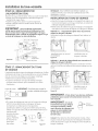
Preparation pour I'installation - Enceinte
PR#PARATION DE L'ENCEINTE DU
LAVE-VAISSELLE
Pour r_duire le risque de choc
_lectdque, d'incendie ou de blessures,
l'instellateur doit s'essurer, au moment
de l'instellation, que le leve-veisselle est
compl_tement enclos.
• L'ouverture de I'armoire non d_grossie doit avoir une largeur
et une profondeur d'au moins 61 cm (24 po) et une hauteur
de 87 cm (34-1/4 po)_+6 mm (1/4 po) du sol 6 la surface du
dessous du plan de travail.
• II ne peut g avoir ni tugaux, ni ills _lectriques sur la paroi
arri_re.
Lesarmoires adjacentes doivent _tre 6 I'_querre et d'aplomb
pour assurer un encastrement parfait. Voir la figure A.
En cas d'installation duns un coin, pr_voir un d_gagement
d'au moins 5 cm (2 po) entre le lave-vaisselle et lemur
adjacent.
Pr_voir un d_gagement d'au moins 72 cm (28-3/8 po)devant
le lave-vaisselle pour permettre I'ouverture complete de la
porte. Voir la figure B.
• IIfaut installer le lave-vaisselle 6 moins de 3 m (10 pi) de
I'_vier pour que I'_coulement suit ad_quat.
Lelave-vaisselle doit _tre enti_rement enclos sur le haut, les
c6t_s et I'arri_re.
Lelave-vaisselle ne peut toucher aucune partie de I'enceinte.
Plandetravail
Lave-vaisselle
i minimumde
(2po)
D_gegements :
Encas d'instullation duns un coin, pr_voir
un d_gagement d'au moins 5 cm (2 po)
entre le lave-vaisselle et lemur adjacent
ou un autre appareil _lectrom_nager.
Pr_voir un d_gagement d'au moins 72 cm
(28-3/8 po) devant le lave-vaisselle.
minimumde72cm
(28-3/8po)
cm
Figure B
au m_me niveau
que le sol de la piece
Figure A
_inlmum
_ 6_,r6r_u°'ree
__ N_ pl°mb
La plomberie et les fils
61ectriques doivent entrer dans
la zone hachur6e
• V6rifier que le sol 6I'int6rieur de I'ouverture d'armoire est
plane et 6 niveau avec le rev6tement de sol de la cuisine. Ceci
facilite I'enl_vement du lave-vaisselle en cas de r6paration
ult6rieure, si n6cessaire.
Conditions sp_ciales s'appliquant _ un lave-vaisselle mont_
sur une plate-forme
La plate-forme doit _tre plane et 6 niveau.

Preparation pour l'installation - Vidange
PRI_PARATION DE LA PLOMBERIE DE
VIDANGE
Exigences de vidange
• Letugau devidange ne peut pas _tre plus de 3 m (10 pi)
de long.
• Une boucle de vidange #lev#e ou un dispositif anti-siphon
est requis. Voir ci-dessous.
M_thode de vidange
Letype d'installation de vidange est li_ aux conditions suivantes :
• Est-ce que les codes ou r_glements Iocaux exigent un
dispositif anti-siphon ?
• Est-ce que le raccord en t# d'#gout se trouve 6 moins de 46
cm (18 po) du sol ?
Si la r#ponse 6 une de ces questions est OUI,il faut utiliser un
dispositif anti-siphon. Se reporter 6 la m_thode 1 (figure ¢) des
illustrations adjacentes.
Si la r#ponse est non aux deux questions, il faut utiliser soit un
dispositif anti-siphon, soit une boucle de vidange #lev#e. Se
reporter 6 la m_thode 1 (figure ¢) ou la m_thode 2 (figure D)
des illustrations adjacentes.
REMARQUE: LQhauteur d'#l#vation du tugau de vidange
ne peut d#passer 122 cm (48 po).
Conditions sp_dales s'appliquant (_un lave-vaisselle mont_
sur plate-forme
Encas d'installation du lave-vaisselle sur une plate-forme, il
faut pr#voir une boucle de vidange #lev#e d'au moins 81 cm
(32 po)au-dessus de la plate-forme en plus du dispositif anti-
siphon ou de la boucle de vidange pr#vu pr#c#demment. ¢ette
mesure assure un #coulement ad#quat de I'eau.
PRUDENCE:
II FAUTutiliser un dispositif anti-siphon si le raccord du
tugau de vidange au raccord en t_ d'_gout ou au brogeur
(_d_chets est (_moins de 46 cm 118po) du niveau du sol. Le
lave-vaisselle risque de ne pas se vidanger correctement
et de s'endommager si le raccord de vidange n'est pas 6
la bonne hauteur avec un dispositif anti-siphon ou une
boucle de vidange _lev_e d'au moins 81 cm 132po).
MI_THODE i - Dispositif anti-siphon avec raccord
en t_ d'@gout ou de brogeur _ d_chets
Figure C
Installationavec un raccord
en t# d'#gout
__ fa
Installation avec un
brogeur 6 d_chets
MI_THODE 2 - Boucle de vidange _lev_e avec un
raccord en t_ d'_gout ou brogeur 6 d_chets
Utiliser le porte-tugau de vidange compris dans le kit de
montage pour suspendre le tugau de vidange sous le plan de
travail. ¢eci sera accompli 6 une _tape ult_rieure.
minimum
Installationavecun raccord
ent_ d'_gout
Installationavecun
brogeur_ d_chets
Installer le raccord en t_ d'_gout ou le brogeur et le dispositif
anti-siphon selon les directives du fabricant.
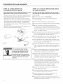
Preparation de I'armoire pour I'installation du
tugau de vidange
Percer un trou de 38 mm (1-1/2 po)dans la paroi de I'armoire
dans la zone hachur_e indiqu_e (_la figure A pour le passage
du tugau de vidange. V_rifier que les bords du trou sont lisses.
Dans une _tape ult_rieure, il faut glisser le tugau devidange au
travers du trou pour le raccorder au drain.
IMPORTANT- Pendantle
branchement du tugau de vidange _[_
au brogeur 6 d_chets, v_rifier que
le bouchon de vidange a _t_ enlev&
Le lave-vaisselle ne peat passe vider
si le bouchon est en place.
_1 Enlever
le bouchon
de vidange
La page est en cours de chargement...
La page est en cours de chargement...
La page est en cours de chargement...
La page est en cours de chargement...
La page est en cours de chargement...
La page est en cours de chargement...
La page est en cours de chargement...
La page est en cours de chargement...
La page est en cours de chargement...
La page est en cours de chargement...
La page est en cours de chargement...
La page est en cours de chargement...
-
 1
1
-
 2
2
-
 3
3
-
 4
4
-
 5
5
-
 6
6
-
 7
7
-
 8
8
-
 9
9
-
 10
10
-
 11
11
-
 12
12
-
 13
13
-
 14
14
-
 15
15
-
 16
16
-
 17
17
-
 18
18
-
 19
19
-
 20
20
-
 21
21
-
 22
22
-
 23
23
-
 24
24
-
 25
25
-
 26
26
-
 27
27
-
 28
28
-
 29
29
-
 30
30
-
 31
31
-
 32
32


GE GDWF100R30WW Guide d'installation
- Catégorie
- Lave-vaisselle
- Taper
- Guide d'installation
dans d''autres langues
- English: GE GDWF100R30WW Installation guide
Documents connexes
-
GE ZBD8900P30II Guide d'installation
-
Hotpoint HDA2160H45SS Guide d'installation
-
-
-
-
GE GDT535PSMSS Guide d'installation
-
GE GDT535PSMSS Guide d'installation
-
GE Profile GLD5800PWW Manuel utilisateur
-
GE 1086800 Guide d'installation
-