
5
insTALLATion procEdurE
Improper installation, adjustment, alteration, service or
maintenance can cause injury or property damage.
Installation must conform to requirements of authority
1.
having jurisdiction or, in absence of such requirements,
to Canadian Electrical Code, CSA C22.1 Part 1, and/or
any local regulations in Canada, or National Electrical
Code, ANSI/NFPA to (Latest Edition) and/or any local
regulations and codes in the USA. Reference should
also be made to local Electric utility regulations and
other codes in effect in the area in which installation is
to be made.
Where required by authority having jurisdiction,
2.
installation must conform to American Society of
Mechanical Engineers Safety Code for Controls and
Safety Devices for Automatically Fired Boilers, ANSI/
ASME No. CSD-1.
3.
!
CAUTION
Do not install boiler under potential water
source.
(RULE OF THUMB: Water Under Wires.)
Electric Hydronic Block units are provided with
4.
mounting brackets for easy wall mounting. Use of
lag screws or anchor bolts through holes provided, or
on 3/4" plywood panel. On uneven walls, suggested
mounting surface be provided such as two 2 x 4’s.
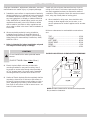
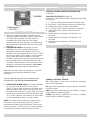
Surface of Electric Hydronic Block except back
5.
shall be
mounted no closer than 20 inches to wall surface on
left and 20 inches minimum to wall surface on right or
more, depending on plumbing. Allow sufcient room
from front of unit to door or wall to remove cover - at
least 12 inches minimum.
20”
MIN
20”
MIN
10”
MIN
5’-3”
SUGGESTED
HEIGHT FOR
EASE OF
INSTALLATION
Greater clearances for access should supercede
re protection clearance.
Install unit with minimum clearance from top of unit to
ceiling of 16 inches. If minimum requirements of space
are used, suggested enclosure be exposed to means of
ventilation. Electric Hydronic Block unit must be mounted
level, using top of back plate as leveling point.
When installed in utility room, door should be wide
6.
enough to allow largest boiler part to enter, or to
permit replacement of another appliance such as water
heater.
Minimum clearances to combustible constructions
are:
TOP ........................................................... 16 IN.
FRONT ...................................................... 12 IN.
LEFT SIDE................................................. 20 IN.
RIGHT SIDE .............................................. 20 IN.
REAR ........................................................... 0 IN.
BOTTOM....................................................10 IN.

6
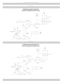
System should be designed as primary/secondary piping
and to operate with a maximum output temperature of
180ºF or lower and a temperature rise across the unit
of 20ºF or lower. Refer to tables below and Figures 2
& 3.
6 2.0
8 2.7
10 3.4
12 4.1
12 4.1
16 5.5
20 6.8
24 8.2
* Flow rate based on 20°ΔT
CONNECTING SUPPLY AND RETURN PIPING
1. Maintain minimum clearance of one inch to hot
water pipes.
2. Hot water boilers installed above radiation level must
be provided with low water cutoff device either as
part of boiler or at time of boiler installation.
4. Suggested plumbing arrangements are illustrated in
Figures 2 & 3. Inlet or return pipe is located at bottom
of unit. Reverse ow will result in noisy operation
and cause very early element failure. Drain cock is
to be located at lowest point of piping.
5. Outlet or supply pipe line to radiation is located at top
of unit. Combination temperature pressure (altitude)
gauge is provided with each unit and should be
installed close to boiler outlet. It is important gauge
sensor be completely immersed in owing water
to assure correct temperature readings. Manual or
automatic water make up supply may be located in
this area below. Circulator pump should be installed
on supply side (pumping away).
6. Install gate valves at locations shown in Figures 2
& 3, so any boiler servicing requiring removal of
water can be done quickly and easily. Not illustrated
but recommended is installation of air vents at high
points of hydronic system. Devices will reduce initial
start up time and help avoid element burnout during
entire life of heating system.
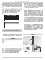
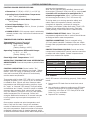
7. Pressure relief valve is supplied with each Electric
Hydronic Block and should be installed at the location
and discharge direction shown in Figure 1, using
pipe nipple and elbow supplied. Piping should be
added so that any water discharged will not damage
boiler or other system components.
PLUMBING AND
ACCESSORY
INSTALLATION
8. For further piping information refer to Hydronics
Institute (I=B=R) manual 200 (Installation Guide
for Residential Hydronics).
figurE 1
3. When boiler is connected to heating system utilizing
multiple zone circulators, each circulator must be
supplied with ow control valve to prevent gravity
circulation.
dEsign of WATEr circuLATing sysTEm
NOTICE
Return water temperature must be higher
than room temperature in which boiler is
installed to prevent condensation.
NOTICE
In some states low water cutoff device
(LWCO) may be required. Check your local
codes.
NOTICE
Reduced pressure back ow preventer must
be present under provisions required by
Environmental Protection Agency, (EPA).

7
primAry/sEcondAry piping
figurE 2
figurE 3

8
connEcTing ELEcTricAL poWEr suppLy
Wiring THE BoiLEr
!
WARNING
Do not use aluminum wire!!
Argo Electric Hydronic Boilers are pre-wired for use with
240-volt, 3 wire, single-phase, 50/60-hertz power. See
Table A on page 4 for reduction in boiler capacity when line
voltage is less than 240 volts.
Opening provided in jacket bottom panel for eld wiring,
refer to rating chart for recommended wire sizes.
Electrical wiring shall be done in accordance with Canadian
Electrical Code, CSA C22.1 Part 1, authority having
jurisdiction in Canada, or National Electrical code, ANSI/
NFPA 70 and/or authority having jurisdiction in USA. Verify
nameplate rating and check related codes to properly size
conductors, switches and over current protection. Several
openings are provided on bottom of cabinet for different
voltage connections. Wire connections refer to wiring
diagram on inside of boiler front cover.
All circuit breakers or disconnects ahead of boiler must
be OFF. If boiler contains integral breakers (depending on
option), it is recommended they are also turned off at this
time. Remove boiler front cover by removing 4 screws from
top and sides.
If boiler is used in multiple zone system, the zone valves
must be powered from independent source and have
electrically isolated end switches or isolating relays wired in
parallel to boiler thermostat terminals.
Wiring on conTroL
Connect only 120 Vac 1/6 HP (maximum)
pump to terminals C1(L) and C2(N) on controller. Strip
wire ends before inserting into terminal block. Tighten
terminal screws.
Connect thermostat or zone valve
end switch to terminals TT and TT (Figure 4).
Strip
wire ends before inserting into terminal block. Tighten
terminal screw clamps.
2/0-6 120
8 40
10-14 35
figurE 4
fiELd Wiring
Wire Size AWG Class B Class C
10 7 19
8 7 19
6 7 19
4 7 19
3 7 19
2 7 19
1 19 37
1/0 19 37
2/0 19 37
Class B - Power cables
Class C - Power cables where more exibility is desired
All Field wiring shall be in accordance with NEC or CEC •
standards. Minimum Circuit Ampacity (MCA) and recom-
mended Maximum Overcurrent Protection (MOP) are list-
ed on nameplate of unit, see Table A.
Use Copper conductors only.•
Use only Class B or C Stranded wire. See Table B.•
Wire Strip Length: 11/16” (Minimum). (Refer to eld wir-•
ing diagram).
Wire must be fully inserted into terminal block, touching •
back of entrance hole.
Field terminal wire lugs shall be tightened in accordance •
with manufacture's recommended torque specications
using appropriate torque wrench. Proper toque settings
are listed on terminal block, see Table C.
Hex head wrench size required for Terminal Block: 5/16”. •
For Circuit Breaker: Flat Screwdriver.
Do not use wire grease on wire termination connections •
and terminal block. This will change torque properties.
The Terminal block was not tested or approved using wire
grease.
fiELd Wiring diAgrAm
Hold lug at specied torque for 5 seconds before releasing. •
When tightening this will ensure any cold ow of material
is compensated for.

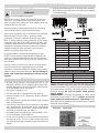
9
conTroL informATion
0.8A max.
(Figure 6)
A total of 8 LED indicator lights display the following
information:
T-T (Green): LED lit when thermostat calling for heat.
1.
Fault (Red): LED lit/ashes operating error/safety fault.
2.
Safety Switch (Green): LED no safety faults.
3.
Circ (Green): LED circulator terminals are energized.
4.
Heating Element#1 (Green): LED element#1 is
5.
energized.
Heating Element #2 (Green): LED element #2 is
6.
energized.
Heating Element #3 (Green): LED element #3 is
7.
energized.
Heating Element #4 (Green): LED element #4 is
8.
energized.
LimiT conTroL opErATion
When boiler water temperature exceeds high limit
1.
setting on aquastat, all heating element control relays
are instantly de-energized. Circulator continues
to operate until call for heat ends. When water
temperature drops below aquastat re-set differential,
heating element power relays close as per time delay
sequence.
2.
: Depending on model
designation, the electric Hydronic Block may be
energized by following alternating current service
entrances: 240 volt single phase 50 or 60 cycle 3 wire.
Wire size see Table A. Sizes listed for various capacity
units include total amperes necessary to operate
elements, circulator and zone valves where used. Wire
sizes specied conform to Canadian Electrical Code
(Canada) or National Electric Code (USA) and include
derating for ampacity and temperature.
Check state and local requirements.
Read data name plate before connecting unit. Electrical
connections are provided and located for proper
installation.
Use only copper wire of proper size and make sure all
terminations are tight.
3.
Terminals identied
as C1(L) and C2(N) at bottom of control panel
(Figure 5) may be used to supply one circulator pump
power. Circulator motor shall not be larger than 1/6
horsepower with maximum 5.0 amp rating. Wiring from
control panel to the pump should have insulation rated
75°C. Circuit protection is provided by 15 amp breaker
or fuse (depending on option) on control board.
If circulator pump is larger than maximum size
listed above, separate circulator pump relay must be
provided with separate overload protection. Where more
than one circulator is used for zoning, it must be installed
and protected according to approved electrical codes.
figurE 5
figurE 6
Thermostat or zone valve end switch, switching
input, closed activation.
High limit temperature sensors (factory installed),
normally closed.
Low water cutoff (optional) end switch, normally
closed (factory installed jumper).
Flow switch (optional) end switch, normally
closed (factory installed jumper).
connEcTing ELEcTricAL poWEr suppLy

10
conTroL informATion Continued
Degrees Fahrenheit
90°F - 180°F
(Factory Setting: 180°F)
+/- 4°F - +/- 20°F
(Factory Setting: 12°F)
200°F
Internal temperature potentiometer
on control.
Control switch "On"
position and safety end switches are closed, "Safety
Switch" LED is lit. Once in operating mode, control
uses well-mounted (RTD) sensor to continuously
monitor water temperature.
Thermostat calls for heat ("TT" LED is lit), control will
energize circulator ("Circ" LED is lit) for 30 seconds
to establish ow. Control will then measure water
temperature and differential setting, perform check
for "open" or "shorted" RTD sensor, verify all safety
end switches are "closed," check for stuck or welded
element relay contacts. Next, control will energize
only one element ("Element" LED is lit) and monitor
water temperature for 60 seconds. Control will
energize additional elements at 30 second intervals
to bring system up to set point temperature in 5
minutes.
Once system reaches set point temperature and
there is still call for heat, control will modulate
number of elements on and off in order to maintain
set point temperature. Required number of elements
energized is determined by heating demand, which
is difference between actual boiler water temperature
and set point temperature.
After call for heat has been satised, elements will
de-energize ("Element" LEDs turn off) by control and
. After 3 minutes control
will de-energize circulator ("Circ" LED turns off).
If during start-up or during operation safety end
switch opens its respective contact, control de-
energizes all elements, continues to energize
circulator, and ashes visible fault code ("Fault" LED
ashes) along with audible fault code. (See fault
codes (below)) Control has built-in reset function.
Water "Set point"
temperature adjustment dial on control should be set
at designed boiler water temperature.
Control mounted using
1/2" tall plastic standoffs. Indicator LEDs are visible
through clear polycarbonate viewing window on front
cover.
Control and other
components located within control panel are sensitive
to water and other liquids. Protect components on
panel from contact with liquids.
1 Safety switch fault
2 Stuck/welded element relay contact
3 RTD short
4 RTD open
Verify RTD sensor is functioning properly, follow steps
below.
Remove both RTD leads from terminal block control
1.
board.
Use multimeter to take ohm reading across RTD leads.
2.
Properly functioning RTD will produce reading of ap-
proximately 1000 ohms at 70°F. Faulty RTD will read
either 0 or 1 on multimeter.
Replace RTD if necessary.
3.
5-7/8"(W) x 9-3/8" (L) x 1-5/8" (H)
90°F - 180°F (adjustable)
200°F (xed)
120V ac
120V ac, 5A max. (circulator
terminal)
120V ac pump output is switched by
onboard circulator relay. Load current limited must not
exceed 5A.

11
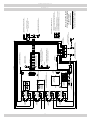
HEATING ELEMENTS
ENERGIZED
(ACTIVATION DES
ÉLÉMENTS DE
CHAUFFAGE)
SOURCE POWER, 240V/60HZ/1PH 3-WIRE, BY OTHERS
(SOURCE DU COURANT, 240V/60HZ/1PH 3-FILS, OU AUTRES)
EQUIPMENT GROUNDING LUG
(TENON DE PRISE Á LA TERRE DE Ľ APPAREIL)
N
NEUTRAL BLOCK
(BLOC NEUTRE)
WHT (BLANC)
WHT/BLK (BLANC/NOIR)
BLK (NOIR)
NOT USED
(NON UTILISÉ)
NOT USED
(NON UTILISÉ)
L
OFF
(FERMÉ)
120VAC
CIRC
C1
C2
NL
CIRC
N
120VAC
INPUT
(ENTRÉE)
WHT (BLANC)
NOT USED
(NON UTILISÉ)
NOT USED
(NON UTILISÉ)
CONTROL
(COMMANDE)
RED (ROUGE)
TRANSFORMER
(TRANSFORMATEUR)
ON
(OUVERT)
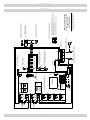
ARGO "AT" ELECTRIC BOILER
SCHEMATIC WIRING DIAGRAM
2 ELEMENT BOILER,
WITH POWER BLOCK
WHT/BLK (BLANC/NOIR)
WHT (BLANC)
WHT/BLK (BLANC/NOIR)
WHT (BLANC)
L1
H2
L2
L2
H1
H2
RED (ROUGE)
LWC
FLOW
FLOW
LWC
RED (ROUGE)
HL
HL
TT
TT
FAULT
(DÉFAILLANCE)
4
1
3
2
SAFETY SWITCHES
(INTERRUPTEURS DE SÉCURITÉ)
T-T
WHT/BLK (BLANC/NOIR)
L1
H1
WHT (BLANC)
RTD
SETPOINT
(RÉGLAGE)
DIFFERENTIAL
(DIFFÉRENTIEL)
THERMOSTAT, BY OTHERS
(THERMOSTAT, OU AUTRES)
L1
POWER BLOCK
(BLOC DE PUISSANCE)
L2
FUSE BLOCK
(BLOC DE FUSIBLE)
WIRE LEGEND / (LÉGENDE DES FILS)
- DRY CONTACT WIRING (POSE DES CÂBLES DE CONTACT SEC)
- 120 VOLT WIRING (POSE DES CÂBLES 120 VOLT)
- 240 VOLT WIRING (POSE DES CÂBLES 240 VOLT)
- 120 VOLT FIELD WIRING (POSE DES CÂBLES 120 VOLT SUR EN CHANTIER)
- 240 VOLT FIELD WIRING (POSE DES CÂBLES 240 VOLT EN CHANTIER)
- DRY CONTACT FIELD WIRING (POSE DES CÂBLES DE CONTACT SEC EN CHANTIER)
(DIAGRAMME SCHÉMATIQUE DU CÂBLAGE
D'UNE CHAUDIÈRE À 2 ÉLÉMENTS)
HIGH LIMIT SAFETY SWITCH, AUTO RESET
(INTERRUPTEUR DE SÉCURITÉ DE LIMITE SUPÉRIEURE,
REMISE EN MARCHE AUTOMATIQUE)
HIGH LIMIT SAFETY SWITCH, AUTO RESET
(INTERRUPTEUR DE SÉCURITÉ DE LIMITE SUPÉRIEURE,
REMISE EN MARCHE AUTOMATIQUE)
OPTIONAL FLOW SWITCH, BY OTHERS
(INTERRUPTEUR DE DÉBIT - FACULTATIF, OU AUTRES)
SOURCE POWER, 120V/60HZ/1PH , BY OTHERS
(SOURCE DU COURANT, 120V/60HZ/1PH, OU AUTRES)
OPTIONAL LWCO, BY OTHERS
(ISPOSITIF D'ARRET EN CAS FAIBLE NIVEAU D'EAU -
FACULTATIF - OU AUTRES)
RTD WATER TEMPERATURE SENSOR
(CAPTEUR DE LA TEMPÉRATURE DE ĽEAU RTD)
CIRCULATOR PUMP, BY OTHERS
(POMPE DE ĽACCELERTEUR, OU AUTRES)
CIRCULATOR RELAY
(RELAIS DU
ĽACCELERTEUR)
FACTORY INSTALLED JUMPERS
(CALVALIERS INSTALLÉES Á ĽUSINE)
ARGO ELECTRONIC BOILER CONTROL
(COMMANDE ÉLECTRONIQUE DE LA CHAUDIÈRE ARGO)
ELEMENT #1
(ÉLÉMENT No1)
ELEMENT #1 RELAYS
(RELAIS DE ĽÉLÉMENT No1)
ELEMENT #2
(ÉLÉMENT No2)
ELEMENT #2 RELAYS
(RELAIS DE ĽÉLÉMENT No2)
,!"%,02).4%$/.7()4%02%3352%3%.3)4)6%
-!4%2)!,7)4(",!#+4%84
./4%
Wiring diAgrAms
figurE 7A

12
- DRY CONTACT FIELD WIRING (POSE DES CÂBLES DE CONTACT SEC EN CHANTIER)
LOAD CENTER
(CENTRE DE CHARGE)
ON
(OUVERT)
TRANSFORMER
(TRANSFORMATEUR)
NEUTRAL BLOCK
(BLOC NEUTRE)
EQUIPMENT GROUNDING LUG
(TENON DE PRISE Á LA TERRE DE Ľ APPAREIL)
WHT (BLANC)
WHT/BLK (BLANC/NOIR)
CIRCULATOR PUMP, BY OTHERS
(POMPE DE ĽACCELERTEUR, OU AUTRES)
N
SOURCE POWER, 240V/60HZ/1PH 3-WIRE, BY OTHERS
(SOURCE DU COURANT, 240V/60HZ/1PH 3-FILS, OU AUTRES)
120VAC
INPUT
(ENTRÉE)
N
CIRC
NOT USED
(NON UTILISÉ)
CIRCULATOR RELAY
(RELAIS DU
ĽACCELERTEUR)
L N
C2
C1
120VAC
CIRC
NOT USED
(NON UTILISÉ)
OFF
(FERMÉ)
BLK (NOIR)
2
1
L
L1
L2
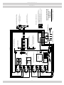
ARGO "AT" ELECTRIC BOILER
SCHEMATIC WIRING DIAGRAM
2 ELEMENT BOILER,
WITH BREAKERS
(DIAGRAMME SCHÉMATIQUE DU CÂBLAGE
D'UNE CHAUDIÈRE À 2 ÉLÉMENTS)
- 240 VOLT FIELD WIRING (POSE DES CÂBLES 240 VOLT EN CHANTIER)
- 120 VOLT FIELD WIRING (POSE DES CÂBLES 120 VOLT SUR EN CHANTIER)
- 240 VOLT WIRING (POSE DES CÂBLES 240 VOLT)
- 120 VOLT WIRING (POSE DES CÂBLES 120 VOLT)
OPTIONAL LWCO, BY OTHERS
(ISPOSITIF D'ARRET EN CAS FAIBLE NIVEAU
D'EAU - FACULTATIF - OU AUTRES)
SOURCE POWER, 120V/60HZ/1PH , BY OTHERS
(SOURCE DU COURANT, 120V/60HZ/1PH, OU AUTRES)
OPTIONAL FLOW SWITCH, BY OTHERS
(INTERRUPTEUR DE DÉBIT - FACULTATIF, OU AUTRES)
THERMOSTAT, BY OTHERS
(THERMOSTAT, OU AUTRES)
ELEMENT #1
(ÉLÉMENT No1)
ELEMENT #1 RELAYS
(RELAIS DE ĽÉLÉMENT No1)
H2
HEATING ELEMENTS
ENERGIZED
(ACTIVATION DES
ÉLÉMENTS DE
CHAUFFAGE)
ARGO ELECTRONIC BOILER CONTROL
(COMMANDE ÉLECTRONIQUE DE LA CHAUDIÈRE ARGO)
NOT USED
(NON UTILISÉ)
NOT USED
(NON UTILISÉ)
RED (ROUGE)
CONTROL
(COMMANDE)
T-T
SAFETY SWITCHES
(INTERRUPTEURS DE SÉCURITÉ)
2
3
1
4
FAULT
(DÉFAILLANCE)
H1
L2
L2
ELEMENT #2
(ÉLÉMENT No2)
H2
ELEMENT #2 RELAYS
(RELAIS DE ĽÉLÉMENT No2)
L1
TT
TT
HL
HL
RED (ROUGE)
LWC
FLOW
FLOW
FACTORY INSTALLED JUMPERS
(CALVALIERS INSTALLÉES Á ĽUSINE)
LWC
DIFFERENTIAL
(DIFFÉRENTIEL)
SETPOINT
(RÉGLAGE)
H1
L1
RTD
RTD WATER TEMPERATURE SENSOR
(CAPTEUR DE LA TEMPÉRATURE DE ĽEAU RTD)
WHT (BLANC)
- DRY CONTACT WIRING (POSE DES CÂBLES DE CONTACT SEC)
RED (ROUGE)
HIGH LIMIT SAFETY SWITCH, AUTO RESET
(INTERRUPTEUR DE SÉCURITÉ DE LIMITE SUPÉRIEURE,
REMISE EN MARCHE AUTOMATIQUE)
WHT (BLANC)
WHT/BLK (BLANC/NOIR)
WHT (BLANC)
WHT (BLANC)
WHT/BLK (BLANC/NOIR)
WHT/BLK (BLANC/NOIR)
WHT (BLANC)
HIGH LIMIT SAFETY SWITCH, AUTO RESET
(INTERRUPTEUR DE SÉCURITÉ DE LIMITE SUPÉRIEURE,
REMISE EN MARCHE AUTOMATIQUE)
WIRE LEGEND / (LÉGENDE DES FILS)
Wiring diAgrAms
figurE 7B

13
WHT/BLK (BLANC/NOIR)
NEUTRAL BLOCK
(BLOC NEUTRE)
WHT/BLK (BLANC/NOIR)
WHT (BLANC)
WHT (BLANC)
WHT (BLANC)
WHT/BLK (BLANC/NOIR)
OFF
(FERMÉ)
ELEMENT #4
(ÉLÉMENT No4)
WHT (BLANC)
L2
H4
ELEMENT #4 RELAYS
(RELAIS DE ĽÉLÉMENT No4)
120VAC
INPUT
(ENTRÉE)
N
L
C1
L
120VAC
CIRC
C2
N
CIRC
H4
L1
L2
H3
WHT/BLK (BLANC/NOIR)
WHT (BLANC)
CONTROL
(COMMANDE)
ON
(OUVERT)
TRANSFORMER
(TRANSFORMATEUR)
HL
T-T
HEATING ELEMENTS
ENERGIZED
(ACTIVATION DES
ÉLÉMENTS DE
CHAUFFAGE)
H2
WHT/BLK (BLANC/NOIR)
L1
H3
ELEMENT #3
(ÉLÉMENT No3)
ELEMENT #3 RELAYS
(RELAIS DE ĽÉLÉMENT No3)
WHT (BLANC)
1
3
L2
2
L1
H2
ELEMENT #2
(ÉLÉMENT No2)
WHT/BLK (BLANC/NOIR)
ELEMENT #2 RELAYS
(RELAIS DE ĽÉLÉMENT No2)
LWC
FLOW
FLOW
LWC
4
FAULT
(DÉFAILLANCE)
SETPOINT
(RÉGLAGE)
WHT/BLK (BLANC/NOIR)
L2
H1
L1
H1
ELEMENT #1
(ÉLÉMENT No1)
WHT (BLANC)
ELEMENT #1 RELAYS
(RELAIS DE ĽÉLÉMENT No1)
RTD
HL
TT
TT
DIFFERENTIAL
(DIFFÉRENTIEL)
WHT (NOIR)
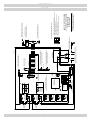
ARGO "AT" ELECTRIC BOILER
SCHEMATIC WIRING DIAGRAM
4 ELEMENT BOILER,
WITH POWER BLOCK
(DIAGRAMME SCHÉMATIQUE DE LA POSE DES
FILS D'UNE CHAUDIÈRE À 4 ÉLÉMENTS)
SOURCE POWER, 240V/60HZ/1PH 3-WIRE, BY OTHERS
(SOURCE DU COURANT, 240V/60HZ/1PH 3-FILS, OU AUTRES)
N
RED (ROUGE)
RED (ROUGE)
RED (ROUGE)
THERMOSTAT, BY OTHERS
(THERMOSTAT, OU AUTRES)
WHT/BLK (BLANC/NOIR)
WHT (BLANC)
FUSE BLOCK
(BLOC DE FUSIBLE)
BLK (NOIR)
L2L1
POWER BLOCK
(BLOC DE PUISSANCE)
- 240 VOLT FIELD WIRING (POSE DES CÂBLES 240 VOLT EN CHANTIER)
EN CHANTIER)
- 120 VOLT WIRING (POSE DES CÂBLES 120 VOLT)
- 240 VOLT WIRING (POSE DES CÂBLES 240 VOLT)
- 120 VOLT FIELD WIRING (POSE DES CÂBLES 120 VOLT SUR EN CHANTIER)
- DRY CONTACT WIRING (POSE DES CÂBLES DE CONTACT SEC)
- DRY CONTACT FIELD WIRING (POSE DES CÂBLES DE CONTACT SEC
WIRE LEGEND / (LÉGENDE DES FILS)
OPTIONAL FLOW SWITCH, BY OTHERS
(INTERRUPTEUR DE DÉBIT - FACULTATIF, OU AUTRES)
OPTIONAL LWCO, BY OTHERS
(ISPOSITIF D'ARRET EN CAS FAIBLE NIVEAU D'EAU -
FACULTATIF - OU AUTRES)
SOURCE POWER, 120V/60HZ/1PH , BY OTHERS
(SOURCE DU COURANT, 120V/60HZ/1PH, OU AUTRES)
EQUIPMENT GROUNDING LUG
(TENON DE PRISE Á LA TERRE DE Ľ APPAREIL)
RTD WATER TEMPERATURE SENSOR
(CAPTEUR DE LA TEMPÉRATURE DE ĽEAU RTD)
HIGH LIMIT SAFETY SWITCH, AUTO RESET
(INTERRUPTEUR DE SÉCURITÉ DE LIMITE SUPÉRIEURE,
REMISE EN MARCHE AUTOMATIQUE)
HIGH LIMIT SAFETY SWITCH, AUTO RESET
(INTERRUPTEUR DE SÉCURITÉ DE LIMITE SUPÉRIEURE,
REMISE EN MARCHE AUTOMATIQUE)
FACTORY INSTALLED JUMPERS
(CALVALIERS INSTALLÉES Á ĽUSINE)
ARGO ELECTRONIC BOILER CONTROL
(COMMANDE ÉLECTRONIQUE DE LA CHAUDIÈRE ARGO)
SAFETY SWITCHES
(INTERRUPTEURS DE SÉCURITÉ)
CIRCULATOR RELAY
(RELAIS DU
ĽACCELERTEUR)
CIRCULATOR PUMP, BY OTHERS
(POMPE DE ĽACCELERTEUR, OU AUTRES)
Wiring diAgrAms
figurE 8A

14
SOURCE POWER, 240V/60HZ/1PH 3-WIRE, BY OTHERS
(SOURCE DU COURANT, 240V/60HZ/1PH 3-FILS, OU AUTRES)
NEUTRAL BLOCK
(BLOC NEUTRE)
WHT/BLK (BLANC/NOIR)
WHT (BLANC)
N
WHT (BLANC)
WHT/BLK (BLANC/NOIR)
WHT (BLANC)
WHT (BLANC)
ELEMENT #4 RELAYS
(RELAIS DE ĽÉLÉMENT No4)
WHT/BLK (BLANC/NOIR)
ELEMENT #4
(ÉLÉMENT No4)
OFF
(FERMÉ)
N
C2
120VAC
CIRC
L
C1
H4
L2
L
N
120VAC
INPUT
(ENTRÉE)
TRANSFORMER
(TRANSFORMATEUR)
H3
L2
L1
H4
CIRC
ON
(OUVERT)
CONTROL
(COMMANDE)
BLK (NOIR)
ARGO "AT" ELECTRIC BOILER
SCHEMATIC WIRING DIAGRAM
4 ELEMENT BOILER,
WITH BREAKERS
L2
L1
ARGO LOAD CENTER
(CENTRE DE CHARGE ARGO)
THERMOSTAT, BY OTHERS
(THERMOSTAT, OU AUTRES)
RED (ROUGE)
T-T
HL
ELEMENT #2 RELAYS
(RELAIS DE ĽÉLÉMENT No2)
ELEMENT #3 RELAYS
(RELAIS DE ĽÉLÉMENT No3)
WHT/BLK (BLANC/NOIR)
ELEMENT #3
(ÉLÉMENT No3)
ELEMENT #2
(ÉLÉMENT No2)
H2
HEATING ELEMENTS
ENERGIZED
(ACTIVATION DES
ÉLÉMENTS DE
CHAUFFAGE)
H3
L1
RED (ROUGE)
H2
L1
FAULT
(DÉFAILLANCE)
4
2
L2
3
1
LWC
FLOW
FLOW
LWC
ELEMENT #1 RELAYS
(RELAIS DE ĽÉLÉMENT No1)
WHT (BLANC)
ELEMENT #1
(ÉLÉMENT No1)
DIFFERENTIAL
(DIFFÉRENTIEL)
H1
L1
SETPOINT
(RÉGLAGE)
H1
L2
TT
TT
HL
RTD
WHT (NOIR)
WHT/BLK (BLANC/NOIR)
WHT (BLANC)
WHT/BLK (BLANC/NOIR)
WHT/BLK (BLANC/NOIR)
WHT (BLANC)
WHT/BLK (BLANC/NOIR)
WHT (BLANC)
RED (ROUGE)
WIRE LEGEND / (LÉGENDE DES FILS)
- DRY CONTACT WIRING (POSE DES CÂBLES DE CONTACT SEC)
- 120 VOLT WIRING (POSE DES CÂBLES 120 VOLT)
- 240 VOLT WIRING (POSE DES CÂBLES 240 VOLT)
- 120 VOLT FIELD WIRING (POSE DES CÂBLES 120 VOLT SUR EN CHANTIER)
- 240 VOLT FIELD WIRING (POSE DES CÂBLES 240 VOLT EN CHANTIER)
(DIAGRAMME SCHÉMATIQUE DU CÂBLAGE
D'UNE CHAUDIÈRE À 4 ÉLÉMENTS)
- DRY CONTACT FIELD WIRING (POSE DES CÂBLES DE CONTACT SEC
EN CHANTIER)
EQUIPMENT GROUNDING LUG
(TENON DE PRISE Á LA TERRE DE Ľ APPAREIL)
OPTIONAL FLOW SWITCH, BY OTHERS
(INTERRUPTEUR DE DÉBIT - FACULTATIF, OU AUTRES)
SOURCE POWER, 120V/60HZ/1PH , BY OTHERS
(SOURCE DU COURANT, 120V/60HZ/1PH, OU AUTRES)
OPTIONAL LWCO, BY OTHERS
(ISPOSITIF D'ARRET EN CAS FAIBLE NIVEAU D'EAU -
FACULTATIF - OU AUTRES)
HIGH LIMIT SAFETY SWITCH, AUTO RESET
(INTERRUPTEUR DE SÉCURITÉ DE LIMITE SUPÉRIEURE,
REMISE EN MARCHE AUTOMATIQUE)
HIGH LIMIT SAFETY SWITCH, AUTO RESET
(INTERRUPTEUR DE SÉCURITÉ DE LIMITE
SUPÉRIEURE, REMISE EN MARCHE AUTOMATIQUE)
FACTORY INSTALLED JUMPERS
(CALVALIERS INSTALLÉES Á ĽUSINE)
RTD WATER TEMPERATURE SENSOR
(CAPTEUR DE LA TEMPÉRATURE DE ĽEAU RTD)
CIRCULATOR PUMP, BY OTHERS
(POMPE DE ĽACCELERTEUR, OU AUTRES)
CIRCULATOR RELAY
(RELAIS DU
ĽACCELERTEUR)
ARGO ELECTRONIC BOILER CONTROL
(COMMANDE ÉLECTRONIQUE DE LA CHAUDIÈRE ARGO)
SAFETY SWITCHES
(INTERRUPTEURS DE SÉCURITÉ)
Wiring diAgrAms
figurE 8B

15
THErmosTAT insTALLATion
sTArTup And sEAsonAL mAinTEnAncE
!
CAUTION
Label all wires prior to disconnection when
servicing controls. Wiring errors can cause
improper and dangerous operation. Verify
proper operation after service.
Use qualied service agency for annual inspection of
boiler and heating system.
Set boiler operating temperature to designed heating
3.
water temperature by adjusting potentiometer dial
located on top center of controller (Figure 4). Adjust
arrow on temperature adjustment dial to water
temperature required.
NOTICE
Boiler is equipped with high-limit temperature
device set at 200° F as safety limit control.
High limit temperature device has automatic
reset function will reset at 170° F.
Turn on hydronic block circuit breaker at service
4.
entrance and/or disconnect switch, depending on
option, and 15 amp circuit breaker on hydronic block.
Set one thermostat above room temperature. Circulator
5.
pump will now operate.
Check system again for leaks. Allow circulator pump to
6.
run until all air has been vented from system. Gurgling
or rushing sound indicates presence of air.
Hydronic block will start to produce heat. Listen for
7.
air passing through system as water temperature
increases. Water pressure will rise somewhat as
temperature increases - this is normal as long as the
pressure remains less than 25 PSIG.
Hydronic block is now ready to be put into service.
Verify hydronic block circuit breaker or switch at service
1.
entrance and, depending on option, hydronic block
circuit breakers within unit are in "Off" position.
NOTICE
Only propylene glycol can be used in heating
system to prevent freezing. Recommendation
is maximum 40% or less propylene glycol
mixture to ensure proper operation of electric
boiler.
Fill heating system with water until pressure is 10-15
2.
PSIG. Check for leaks, repair if necessary, purge all air
from system.
NOTICE
Failure to vent and keep air out of heating
system will result in damage to heating ele-
ments in hydronic block. Damage of this type
is not covered by manufacturer's warranty.
Your Argo AT Boiler will work
with standard and programmable
setback thermostats.
Some programmable thermostats
may cause boiler control T-T LED
to icker on and off when there is
no call for heat, your thermostat
will require an external 24V power
supply (transformer) and isolation
relay or Argo AR822 control.
1. Install thermostat on inside wall ve feet above
oor.
2. NEVER install thermostat on outside wall.
3. Do not install thermostat where it will be affected by
sunlight, drafts, televisions, lighting xtures, hot or
cold pipes, replaces, or chimneys.
4. Instructions for final adjustment of thermostat
(adjusting heating anticipator, calibration, etc.) are
packaged with thermostat.

16
No heat when called by
thermostat and “TT” LED
is NOT lit
Thermostat
Disconnect thermostat from control, momentarily place a jumper across
terminal “TT” & “TT.” If circulator starts, trouble is in thermostat.
No power to board
Conrm control’s On/Off switch is in “ON” position, check 15A circuit
breaker or fuse.
“Circ” LED is NOT lit
when thermostat is call-
ing
Safety fault Check for open contact on safety’s. Conrm continuity across terminals.
No power to board Conrm control’s On/Off switch is in “ON” position
“Safety Switch” LED is
NOT lit when thermostat
is calling
Safety fault Check for open contact on safety’s. Conrm continuity across terminals.
No power to board Conrm control’s On/Off switch is in “ON” position.
“FAULT” LED is ashing Safety fault Refer to “Fault” codes
TrouBLEsHooTing
!
WARNING
Take extreme care when boiler cover is
removed. Turn “OFF” all service to boiler.
"Power On” checks should be made by
qualied electrician.
Heating element change, use following procedure:
Check water pressure of boiler. Should be 15-25 PSIG.
1.
Check for air within system.
2.
This section is to assist service technician when
trouble shooting electric boiler. It is important to
isolate before proceeding. Control error codes can be
helpful identifying cause of problem. If you suspect
wiring fault, check all external wiring and wiring
connections following wiring diagram label on inside
of boiler's cover. Additional wiring diagram is included
with this manual.
Turn off hydronic unit circuit breaker at service en-
1.
trance and/or disconnect switch.
Close gate valves near inlet and outlet of hydronic
2.
block.
noisy BoiLEr
HEATing ELEmEnT cHAngE
When thermostat calls for heat, circulator will be
8.
energized and indicator LED will light. Heating elements
are energized with element indicator LEDs. Once boiler
water temperature reaches set point on temperature
adjustment dial, controller will regulate boiler by
staging its elements. Number of elements which stay
on is based on heating demand and set point of boiler
water temperature. After all room thermostats are
satised with heat, controller de-energizes elements
one after another, and switches pump off after 3
minutes.
THErmosTAT insTALLATion
3.
Close feed line valve if using automatic ll.
Open drain valve and allow water to drain from boiler.
4.
Manual operation of relief valve will assist drainage by
allowing air to enter.
Remove cabinet cover and disconnect two wires
5.
attached to effected heating element.
Remove four bolts securing heating element to casting
6.
pry element loose. Take note of markings on element
ange to assure proper reinstallation.
After element has been removed, carefully clean any
7.
remaining gasket material from casting surface. Take
care not to scratch or score surface.
Install new gasket and heating element while assuring
8.
element is correctly positioned.
Close relief valve. Open feed line valve and check for
9.
leaks. Open gate valves. Install heating element wires
and cabinet cover.
Refer to "Startup and Seasonal Maintenance" for proper
10.
purging of air prior to energizing heating elements.
-
 1
1
-
 2
2
-
 3
3
-
 4
4
-
 5
5
-
 6
6
-
 7
7
-
 8
8
-
 9
9
-
 10
10
-
 11
11
-
 12
12


Argo Technology AT204510B Guide d'installation
- Taper
- Guide d'installation
- Ce manuel convient également à
dans d''autres langues
Autres documents
-
HTP Mod Con Commercial Gas Boiler Installation Drawings
-
Taco Comfort Solutions 0026e ECM High-Efficiency Circulator Pump Manuel utilisateur
-
-
Ingersoll-Rand 400 Manuel utilisateur
-
Laars MT2H0300NACK2BXN Guide d'installation
-
Bradford White BMT2H0300 Manuel utilisateur
-
Emerson White-Rodgers Carrier Integrated Single Stage 120V Hot Surface Ignition Control Kit 50M56D-751 Manuel utilisateur
-
Weil-McLain CER Information produit
-
Frigidaire FGMC3065PF Manuel utilisateur
-
Honeywell Heating System 96-6127-2 Manuel utilisateur