
MagicTouch MT200 VW10
(9101300033)
DE 5 Funk-Fernbedienung
Fahrzeugspezifische Einbauhinweise
EN 9 Radio Remote Control
Vehicle-specific installation
instructions
FR 13 Radiotélécommande
Instructions de montage spécifiques
au véhicule
ES 17 Mando a distancia por radio
Indicaciones para el montaje
específicas del vehículo
IT 21 Radiotelecomando
Indicazioni di montaggio specifiche per
il veicolo
NL 25 Draadloze afstandsbediening
Voertuigspecifieke
inbouwvoorschriften
DA 29 Radio-fjernbetjening
Køretøjsspecifikke
installationshenvisninger
SV 32 Radio-fjärrkontroll
Fordonsspecifika anvisningar för
montering
NO 36 Radio-fjernkontrol
Kjøretøyspesifikke monteringsråd
FI 40 Radiokauko-ohjain
Ajoneuvokohtaiset asennusohjeet
_MT200_VW10.book Seite 1 Montag, 19. April 2010 7:32 19

MagicTouch MT200 VW10
2
1
1
3
2
1
Skoda Fabia: sw/rt
VW Polo: rt/ge
sw
sw/rt
sw/ws
4
sw/gn
2
1
3
_MT200_VW10.book Seite 2 Montag, 19. April 2010 7:32 19

MagicTouch MT200 VW10
3
1
br/bl
2
br/gn
4
12
3
4
ws/bl
sw/bl
sw/ws
sw/gn
5
1
2
ws/bl
ge/bl
6
_MT200_VW10.book Seite 3 Montag, 19. April 2010 7:32 19

MagicTouch MT200 VW10
4
1
2
sw/ws
sw/gn
7
_MT200_VW10.book Seite 4 Montag, 19. April 2010 7:32 19

MagicTouch MT200 VW10 Geeignet zum Einbau in folgende Fahrzeuge
5
Im folgenden finden Sie fahrzeugspezifische Einbauhinweise zu
MagicTouch MT200. Alle weiteren Informationen finden Sie in der Montage-
und Bedienungsanleitung.
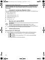
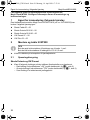
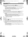
1 Geeignet zum Einbau in folgende Fahrzeuge
Die Funk-Fernbedienung MagicTouch MT200 VW10 (Art.-Nr. 9101300033) kann in
folgenden Fahrzeugtypen verwendet werden:
z Skoda Fabia 00 – 06
z Skoda Octavia SLXi 96 – 00
z Skoda Octavia GLXi 96 – 00
z VW Passat 97 – 00
z VW Polo 02 – 05
2 MT200 montieren und anschließen
I
HINWEIS
Verwenden Sie die roten Schneidverbinder für Leitungen bis max. 1 mm².
Verwenden Sie die blauen Schneidverbinder für Leitungen von 1,5 bis
2,5 mm².
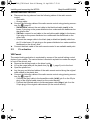
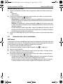
➤ Klemmen Sie das Masseband am Minuspol der Fahrzeugbatterie ab.
2.1 Spannungsversorgung
Skoda Octavia und VW Passat
➤ Klemmen Sie die folgenden Leitungen der Funk-Fernbedienung wie
beschrieben an:
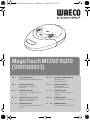
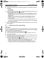
– die rote Leitung an die Schraubklemme „+30“ (unter dem Armaturenbrett,
Abb. 1 1, Seite 2)
– die orange Leitung an die Schraubklemme „75X“ (unter dem Armaturenbrett,
Abb. 1 1, Seite 2)
– die schwarze Leitung an einen vorhandenen Massepunkt
_MT200_VW10.book Seite 5 Montag, 19. April 2010 7:32 19

MT200 montieren und anschließen MagicTouch MT200 VW10
6
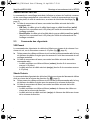
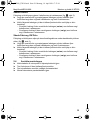
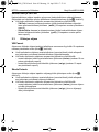
Skoda Fabia und VW Polo
➤ Trennen Sie die Ringhülsen von folgenden Leitungen der Funk-Fernbedienung:
– rote Leitung
– orange Leitung
➤ Verbinden Sie die folgenden Leitungen der Funk-Fernbedienung jeweils mit
Hilfe von Schneidverbindern (Abb. 2, Seite 2):
– Skoda Fabia: die rote Leitung mit der schwarz/roten Leitung (sw/rt) im
braunen 5-poligen Stecker am Stromverteilerkasten unterhalb des
Armaturenbrettes auf der Fahrerseite
– VW Polo: die rote Leitung mit der rot/gelben Leitung (rt/ge) im braunen
5-poligen Stecker am Stromverteilerkasten unterhalb des Armaturenbrettes
auf der Fahrerseite
– die orange Leitung mit der schwarzen (sw) bzw. schwarz/roten (sw/rt)
Leitung aus Pin 12 im braunen 18-poligen Stecker am Stromverteilerkasten
unterhalb des Armaturenbrettes auf der Fahrerseite
➤ Klemmen Sie die schwarze Leitung der Funk-Fernbedienung an einen vor-
handenen Massepunkt an.
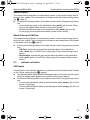
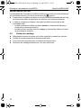
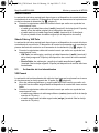
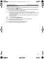
2.2 ZV-Ansteuerung
VW Passat
Die Ansteuerung der Zentralverriegelung erfolgt am Zentralverriegelungs-Steuer-
gerät Ihres Fahrzeuges. Das Steuergerät befindet sich in einer Kunststoffbox unter
dem Teppichboden vor dem Fahrersitz.
➤ Nehmen Sie die Trittleiste auf der Fahrerseite ab.
➤ Heben Sie den Teppichboden an, und ziehen Sie die Kunststoffbox (Abb. 3 1,
Seite 2) hervor.
➤ Öffnen Sie die Kunststoffbox.
➤ Verlegen Sie die graue und blau/rote Leitung der Funk-Fernbedienung am
Original-Kabelstrang entlang zur Kunststoffbox.
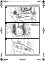
➤ Verbinden Sie die folgenden Leitungen der Funk-Fernbedienung jeweils mit
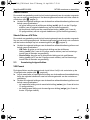
Hilfe von Schneidverbindern (Abb. 4, Seite 3):
– die graue Leitung mit der braun/blauen Leitung (br/bl) (Pin 2 vom 23-poligen
Stecker) vom Original-Kabelstrang (am Steuergerät)
– die blau/rote Leitung mit der braun/grünen (br/gn) Leitung (Pin 4 vom
23-poligen Stecker) vom Original-Kabelstrang (am Steuergerät)
_MT200_VW10.book Seite 6 Montag, 19. April 2010 7:32 19

MagicTouch MT200 VW10 MT200 montieren und anschließen
7
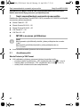
Skoda Octavia
Die Ansteuerung der Zentralverriegelung erfolgt am Zentralverriegelungs-Steuer-
gerät Ihres Fahrzeuges. Das Steuergerät befindet sich links neben der Lenksäule
(Abb. 5, Seite 3).
➤ Verbinden Sie die folgenden Leitungen der Funk-Fernbedienung jeweils mit
Hilfe von Schneidverbindern:
– die graue Leitung mit der weiß/blauen Leitung (ws/bl) (Pin 2 vom 23-poligen
Stecker) vom Original-Kabelstrang (am Steuergerät)
– die blau/rote Leitung mit der schwarz/blauen Leitung (sw/bl) (Pin 4 vom
23-poligen Stecker) vom Original-Kabelstrang (am Steuergerät)
Skoda Fabia und VW Polo
Die Ansteuerung der Zentralverriegelung erfolgt am Zentralverriegelungs-Steuer-
gerät Ihres Fahrzeuges. Das Steuergerät befindet sich im Fußraum auf der Fahrer-
seite am Heizungskasten (Abb. 6, Seite 3).
➤ Verbinden Sie die folgenden Leitungen der Funk-Fernbedienung jeweils mit
Hilfe von Schneidverbindern:
– VW Polo: die graue und die blau/rote Leitung mit der weiß/blauen
Leitung (ws/bl) (Pin 6 vom 23-poligen schwarzen Stecker) vom Zentral-
verriegelungs-Steuergerät
– Skoda Fabia: die graue und die blau/rote Leitung mit der gelb/blauen
Leitung (ge/bl) (Pin 6 vom 23-poligen schwarzen Stecker) vom Zentral-
verriegelungs-Steuergerät
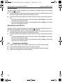
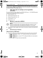
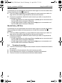
2.3 Blinkeransteuerung
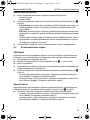
VW Passat
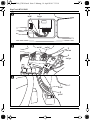
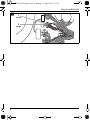
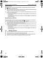
Die Ansteuerung der Fahrzeugblinker erfolgt an der linken A-Säule im Fußraum am
10-poligen braunen Stecker (Abb. 7, Seite 4).
➤ Verlegen Sie die schwarz/weiße und schwarz/grüne Leitung der Funk-Fern-
bedienung am Original-Kabelstrang entlang zum Zentralverriegelungs-Steuer-
gerät.
➤ Verbinden Sie die folgenden Leitungen der Funk-Fernbedienung jeweils mit
Hilfe von Schneidverbindern:
– die schwarz/weiße Leitung mit der schwarz/weißen Leitung (sw/ws) (Pin 9
vom braunen 10-poligen Stecker)
– die schwarz/grüne Leitung mit der schwarz/grünen Leitung (sw/gn) (Pin 9
vom braunen 10-poligen Stecker)
_MT200_VW10.book Seite 7 Montag, 19. April 2010 7:32 19

MT200 montieren und anschließen MagicTouch MT200 VW10
8
Skoda Octavia
Die Ansteuerung der Fahrzeugblinker erfolgt im Kabelstrang an der Lenksäule
(Abb. 5, Seite 3).
➤ Verlegen Sie die schwarz/weiße und schwarz/grüne Leitung der Funk-Fern-
bedienung am Original-Kabelstrang entlang zur Lenksäule.
➤ Verbinden Sie die folgenden Leitungen der Funk-Fernbedienung jeweils mit
Hilfe von Schneidverbindern:
– die schwarz/weiße Leitung mit der schwarz/weißen Leitung (sw/ws) im
Kabelstrang an der Lenksäule.
– die schwarz/grüne Leitung mit der schwarz/grünen Leitung (sw/gn) im Kabel-
strang an der Lenksäule.
Skoda Fabia und VW Polo
Die Ansteuerung der Fahrzeugblinker erfolgt am Stromverteilerkasten unterhalb des
Armaturenbrettes auf der Fahrerseite (Abb. 2, Seite 2).
➤ Verlegen Sie die schwarz/weiße und schwarz/grüne Leitung der Funk-Fern-
bedienung am Original-Kabelstrang entlang zur Lenksäule.
➤ Verbinden Sie die folgenden Leitungen der Funk-Fernbedienung jeweils mit
Hilfe von Schneidverbindern:
– die schwarz/weiße Leitung mit der schwarz/weißen Leitung (sw/ws) im
Kabelstrang an der Lenksäule.
– die schwarz/grüne Leitung mit der schwarz/grünen Leitung (sw/gn) im Kabel-
strang an der Lenksäule.
2.4 Montage abschließen
➤ Klemmen Sie das Masseband am Minuspol der Fahrzeugbatterie wieder an.
➤ Testen Sie die Funktion der Funk-Fernbedienung.
➤ Befestigen Sie das Steuergerät mit dem beiliegenden Befestigungsmaterial.
➤ Montieren Sie demontierte Verkleidungen/Abdeckungen wieder.
_MT200_VW10.book Seite 8 Montag, 19. April 2010 7:32 19

MagicTouch MT200 VW10 Suitable for installing in the following vehicles
9
The following information contains vehicle-specific installation instructions
for MagicTouch MT200. Refer to the installation and operating manual for any
further information.
1 Suitable for installing in the following vehicles
The MagicTouch MT200 VW10 radio remote control (item no. 9101300033) can be
used in the following vehicle types:
z Skoda Fabia 00 – 06
z Skoda Octavia SLXi 96 – 00
z Skoda Octavia GLXi 96 – 00
z VW Passat 97 – 00
z VW Polo 02 – 05
2 Installing and connecting the MT200
I
NOTE
Use a red piercing connector for cables with a cross-section of max. 1 mm².
Use a blue piercing connector for cables with a cross-section of between
1.5 to 2.5 mm².
➤ Undo the strap on the negative terminal of the vehicle battery.
2.1 Power supply
Skoda Octavia and VW Passat
➤ Connect the following cables of the radio remote control as follows:
– Connect the red cable to the “+30” screw terminal (under the dashboard,
fig. 1 1, page 2)
– Connect the orange cable to the “75X” screw terminal (under the dashboard,
fig. 1 1, page 2)
– Connect the black cable to an available earth point
_MT200_VW10.book Seite 9 Montag, 19. April 2010 7:32 19

Installing and connecting the MT200 MagicTouch MT200 VW10
10
Skoda Fabia and VW Polo
➤ Disconnect the ring sleeves from the following cables of the radio remote
control:
– Red cable
– Orange cable
➤ Connect the following cables of the radio remote control using piercing connec-
tors (fig. 2, page 2):
– Skoda Fabia: connect the red cable to the black/red cable (sw/rt) in the
brown, 5-pin plug on the power distributor box underneath the dashboard on
the driver's side
– VW Polo: connect he red cable to the red/yellow cable (rt/ge) in the brown,
5-pin plug on the power distributor box underneath the dashboard on the
driver side
– Connect the orange cable to the black (sw) or black/red (sw/rt) cable from
pin 12 in the brown, 18-pin plug on the power distributor box underneath the
dashboard on the driver's side
➤ Connect the black cable of the radio remote control to an available earth point.
2.2 CL activation
VW Passat
The central locking activation is conducted by means of the central locking control
device of your vehicle. The control device is located in a plastic box under the carpet
in front of the driver's seat.
➤ Remove the skirting board on the driver's side.
➤ Lift up the carpet and pull the plastic box (fig. 3 1, page 2) out to the front.
➤ Open the plastic box.
➤ Lay the grey and blue/red cables of the radio remote control along the original
cable strand to the plastic box.
➤ Connect the following cables of the radio remote control using piercing connec-
tors (fig. 4, page 3):
– Connect the grey cable to the brown/blue cable (br/bl) (pin 2 on the 23-pin
plug) of the original cable strand (on the control device)
– Connect the blue/red cable to the brown/green cable (br/gn) (pin 4 on the
23-pin plug) of the original cable strand (on the control device)
_MT200_VW10.book Seite 10 Montag, 19. April 2010 7:32 19

MagicTouch MT200 VW10 Installing and connecting the MT200
11
Skoda Octavia
The central locking activation is conducted by means of the central locking control
device of your vehicle. The control device is located on the left of the steering column
(fig. 5, page 3).
➤ Connect the following cables of the radio remote control using piercing connec-
tors:
– Connect the grey cable to the white/blue cable (ws/bl) (pin 2 on the 23-pin
plug) of the original cable strand (on the control device)
– Connect the blue/red cable to the black/blue cable (sw/bl) (pin 4 on the
23-pin plug) of the original cable strand (on the control device)
Skoda Fabia and VW Polo
The central locking activation is conducted by means of the central locking control
device of your vehicle. The control device is located on the heating box in the footwell
on the driver's side (fig. 6, page 3).
➤ Connect the following cables of the radio remote control using piercing connec-
tors:
– VW Polo: connect the grey and the blue/red cables to the white/blue
cable (ws/bl) (pin 6 on the 23-pin, black plug) of the central locking control
device
– Skoda Fabia: connect the grey and the blue/red cables to the yellow/blue
cable (ge/bl) (pin 6 on the 23-pin, black plug) of the central locking control
device
2.3 Indicator activation
VW Passat
The activation of the vehicle indicators is conducted on the left A pillar in the footwell
on the 10-pin, brown plug (fig. 7, page 4).
➤ Lay the black/white cable and the black/green cable of the radio remote control
along the original cable strand to the central locking control device.
➤ Connect the following cables of the radio remote control using piercing connec-
tors:
– Connect the black/white cable to the black/white cable (sw/ws) (pin 9 of the
brown, 10-pin plug)
– Connect the black/green cable to the black/green cable (sw/gn) (pin 9 of the
brown, 10-pin plug)
_MT200_VW10.book Seite 11 Montag, 19. April 2010 7:32 19

Installing and connecting the MT200 MagicTouch MT200 VW10
12
Skoda Octavia
Activation of the vehicle's indicators is conducted in the cable strand on the steering
column (fig. 5, page 3).
➤ Lay the black/white cable and the black/green cable of the radio remote control
along the original cable strand to the steering column.
➤ Connect the following cables of the radio remote control using piercing connec-
tors:
– Connect the black/white cable to the black/white cable (sw/ws) in the cable
strand on the steering column
– Connect the black/green cable to the black/green cable (sw/gn) in the cable
strand on the steering column
Skoda Fabia and VW Polo
Activation of the vehicle's indicators is conducted on the power distribution box un-
derneath the dashboard on the driver's side (fig. 2, page 2).
➤ Lay the black/white cable and the black/green cable of the radio remote control
along the original cable strand to the steering column.
➤ Connect the following cables of the radio remote control using piercing connec-
tors:
– Connect the black/white cable to the black/white cable (sw/ws) in the cable
strand on the steering column
– Connect the black/green cable to the black/green cable (sw/gn) in the cable
strand on the steering column
2.4 Completing installation
➤ Reattach the strap on the negative terminal of the vehicle battery again.
➤ Test the radio remote control to see if it works correctly.
➤ Fasten the control device in place using the fastening material supplied.
➤ Remount the panels and covers removed.
_MT200_VW10.book Seite 12 Montag, 19. April 2010 7:32 19

MagicTouch MT200 VW10 Convient pour le montage dans les véhicules suivants
13
Vous trouverez ci-après les instructions de montage spécifiques à la
MagicTouch MT200. Pour de plus amples informations, reportez-vous aux
instructions de montage et de service.
1 Convient pour le montage dans les véhicules
suivants
La télécommande radio MagicTouch MT200 VW10 (réf. 9101300033) peut être
utilisée dans les types de véhicules suivants :
z Skoda Fabia 00 – 06
z Skoda Octavia SLXi 96 – 00
z Skoda Octavia GLXi 96 – 00
z VW Passat 97 – 00
z VW Polo 02 – 05
2 Montage et raccordement de la MT200
I
REMARQUE
Pour les câbles d'une section maximale de 1 mm², utilisez les connecteurs
à lames rouges.
Pour les câbles d'une section maximale de 1,5 à 2,5 mm², utilisez les con-
necteurs à lames bleues.
➤ Débranchez la tresse de masse reliée au pôle négatif de la batterie du véhicule.
2.1 Alimentation électrique
Skoda Octavia et VW Passat
➤ A l'aide de connecteurs à lames, raccordez les câbles suivants de la télé-
commande radio comme indiqué :
– le câble rouge à la borne à vis « +30 » (sous le tableau de bord, fig. 1 1,
page 2)
– le câble orange à la borne à vis « 75X » (sous le tableau de bord, fig. 1 1,
page 2)
– le câble noir à un point de masse existant
_MT200_VW10.book Seite 13 Montag, 19. April 2010 7:32 19

Montage et raccordement de la MT200 MagicTouch MT200 VW10
14
Skoda Fabia et VW Polo
➤ Coupez les gaines des câbles suivants de la télécommande radio :
– câble rouge
– câble orange
➤ A l'aide de connecteurs à lames, raccordez les câbles suivants de la télé-
commande radio (fig. 2, page 2) :
– Skoda Fabia : le câble rouge au câble noir/rouge (sw/rt) du connecteur mar-
ron à 5 pôles situé au niveau du boîtier électrique sous le tableau de bord, du
côté du conducteur
– VW Polo : le câble rouge au câble rouge/jaune (rt/ge) du connecteur marron
à 5 pôles situé au niveau du boîtier électrique sous le tableau de bord, du côté
du conducteur
– le câble orange au câble noir (sw) ou noir/rouge (sw/rt) de la broche 12 du
connecteur marron à 18 pôles situé au niveau du boîtier électrique sous le
tableau de bord, du côté du conducteur
➤ Raccordez le câble noir de la télécommande radio à un point de masse existant.
2.2 Commande du verrouillage centralisé
VW Passat
La commande du verrouillage centralisé s'effectue au niveau de l'unité de comman-
de du verrouillage centralisé de votre véhicule. L'unité de commande se trouve dans
un boîtier en plastique sous le plancher, devant le siège du conducteur.
➤ Retirez la plinthe du côté du conducteur.
➤ Soulevez la moquette et retirez le boîtier en plastique (fig. 3 1, page 2).
➤ Ouvrez le boîtier en plastique.
➤ Faites passer les câbles gris et bleu/rouge de la télécommande radio le long du
faisceau de câbles d'origine pour les amener au boîtier en plastique.
➤ A l'aide de connecteurs à lames, raccordez les câbles suivants de la télé-
commande radio (fig. 4, page 3) :
– le câble gris au câble marron/bleu (br/bl) (broche 2 du connecteur à 23 pôles)
du faisceau de câbles d'origine (au niveau de l'unité de commande)
– le câble bleu/rouge au câble marron/vert (br/gn) (broche 4 du connecteur à
23 pôles) du faisceau de câbles d'origine (au niveau de l'unité de commande)
Skoda Octavia
La commande du verrouillage centralisé s'effectue au niveau de l'unité de comman-
de du verrouillage centralisé de votre véhicule. L'unité de commande se trouve à
gauche, à côté de la colonne de direction (fig. 5, page 3).
➤ A l'aide de connecteurs à lames, raccordez les câbles suivants de la télé-
commande radio :
– le câble gris au câble blanc/bleu (ws/bl) (broche 2 du connecteur à 23 pôles)
du faisceau de câbles d'origine (au niveau de l'unité de commande)
– le câble bleu/rouge au câble noir/bleu (sw/bl) (broche 4 du connecteur à
23 pôles) du faisceau de câbles d'origine (au niveau de l'unité de commande)
_MT200_VW10.book Seite 14 Montag, 19. April 2010 7:32 19

MagicTouch MT200 VW10 Montage et raccordement de la MT200
15
Skoda Fabia et VW Polo
La commande du verrouillage centralisé s'effectue au niveau de l'unité de comman-
de du verrouillage centralisé de votre véhicule. L'unité de commande se trouve au
niveau des pieds, du côté du conducteur, au niveau de la boîte de chauffage (fig. 6,
page 3).
➤ A l'aide de connecteurs à lames, raccordez les câbles suivants de la télé-
commande radio :
– VW Polo : le câble gris et le câble bleu/rouge au câble blanc/bleu (ws/bl)
(broche 6 du connecteur noir à 23 pôles) de l'unité de commande du ver-
rouillage centralisé
– Skoda Fabia : le câble gris et le câble bleu/rouge au câble jaune/bleu (ge/bl)
(broche 6 du connecteur noir à 23 pôles) de l'unité de commande du ver-
rouillage centralisé
2.3 Commande des clignotants
VW Passat
La commande des clignotants du véhicule s'effectue au niveau de la colonne A au
niveau du sol, sur le connecteur marron à 10 pôles (fig. 7, page 4).
➤ Faites passer les câbles noir/blanc et noir/vert de la télécommande radio le long
du faisceau de câbles d'origine pour les amener à l'unité de commande du ver-
rouillage centralisé.
➤ A l'aide de connecteurs à lames, raccordez les câbles suivants de la télé-
commande radio :
– le câble noir/blanc au câble noir/blanc (sw/ws) (broche 9 du connecteur
marron à 10 pôles)
– le câble noir/vert au câble noir/vert (sw/gn) (broche 9 du connecteur marron
à 10 pôles)
Skoda Octavia
La commande des clignotants du véhicule s'effectue au niveau du faisceau de câbles
situé au niveau de la colonne de direction (fig. 5, page 3).
➤ Faites passer les câbles noir/blanc et noir/vert de la télécommande radio le long
du faisceau de câbles d'origine pour les amener à la colonne de direction.
➤ A l'aide de connecteurs à lames, raccordez les câbles suivants de la télé-
commande radio :
– le câble noir/blanc au câble noir/blanc (sw/ws) du faisceau de câbles au
niveau de la colonne de direction.
– le câble noir/vert au câble noir/vert (sw/gn) du faisceau de câbles au niveau
de la colonne de direction.
_MT200_VW10.book Seite 15 Montag, 19. April 2010 7:32 19

Montage et raccordement de la MT200 MagicTouch MT200 VW10
16
Skoda Fabia et VW Polo
La commande des clignotants du véhicule s'effectue au niveau du boîtier électrique
sous le tableau de bord, du côté du conducteur (fig. 2, page 2).
➤ Faites passer les câbles noir/blanc et noir/vert de la télécommande radio le long
du faisceau de câbles d'origine pour les amener à la colonne de direction.
➤ A l'aide de connecteurs à lames, raccordez les câbles suivants de la télé-
commande radio :
– le câble noir/blanc au câble noir/blanc (sw/ws) du faisceau de câbles au
niveau de la colonne de direction.
– le câble noir/vert au câble noir/vert (sw/gn) du faisceau de câbles au niveau
de la colonne de direction.
2.4 Finition du montage
➤ Rebranchez la tresse de masse sur le pôle négatif de la batterie du véhicule.
➤ Vérifiez le fonctionnement de la télécommande radio.
➤ Fixez l'unité de commande avec le matériel de fixation fourni.
➤ Remontez les habillages/caches que vous avez démontés.
_MT200_VW10.book Seite 16 Montag, 19. April 2010 7:32 19

MagicTouch MT200 VW10 Adecuado para el montaje en los siguientes vehículos
17
A continuación encontrará las indicaciones para el montaje específicas del
vehículo para el MagicTouch MT200. El resto de información la encontrará en
las instrucciones de montaje y de uso.
1 Adecuado para el montaje en los siguientes
vehículos
El control remoto por radio MagicTouch MT200 VW10 (art. n.° 9101300033) puede
utilizarse en los siguientes tipos de vehículos:
z Skoda Fabia 00 – 06
z Skoda Octavia SLXi 96 – 00
z Skoda Octavia GLXi 96 – 00
z VW Passat 97 – 00
z VW Polo 02 – 05
2 Montar y conectar el MT200
I
NOTA
Utilice los conectores de corte rojos para cables de un máx. de 1 mm².
Utilice los conectores de corte azules para cables de 1,5 a 2,5 mm².
➤ Desconecte el polo negativo de la cinta de conexión al chasis de la batería del
vehículo.
2.1 Alimentación de tensión
Skoda Octavia y VW Passat
➤ Conecte los siguientes cables del control remoto por radio como se describe:
– el cable rojo al borne roscado “+30” (debajo del tablero de instrumentos,
fig. 1 1, página 2)
– el cable naranja al borne roscado “75X” (debajo del tablero de instrumentos,
fig. 1 1, página 2)
– el cable negro a un punto de masa disponible
_MT200_VW10.book Seite 17 Montag, 19. April 2010 7:32 19

Montar y conectar el MT200 MagicTouch MT200 VW10
18
Skoda Fabia y VW Polo
➤ Retire los casquillos anulares de los siguientes cables del control remoto por
radio:
– cable rojo
– cable naranja
➤ Conecte los siguientes cables del control remoto por radio con ayuda de los
conectores de corte (fig. 2, página 2):
– Skoda Fabia: el cable rojo al cable negro/rojo (sw/rt) de la clavija marrón de
5 polos del armario de distribución por debajo del tablero de instrumentos del
lado del conductor
– VW Polo: el cable rojo al cable rojo/amarillo (rt/ge) de la clavija marrón de
5 polos del armario de distribución por debajo del tablero de instrumentos del
lado del conductor
– el cable naranja al cable negro (sw) o negro/rojo (sw/rt) del terminal 12 de la
clavija marrón de 18 polos del armario de distribución por debajo del tablero
de instrumentos del lado del conductor
➤ Conecte el cable negro del control remoto por radio a un punto de masa dispo-
nible.
2.2 Activación del cierre centralizado
VW Passat
La activación del cierre centralizado tiene lugar en el dispositivo de control del cierre
centralizado de su vehículo. El dispositivo de control se encuentra delante del asien-
to del conductor en una caja de plástico debajo de la moqueta.
➤ Retire el estribo del lado del conductor.
➤ Levante la moqueta y saque la caja de plástico (fig. 3 1, página 2).
➤ Abra la caja de plástico.
➤ Lleve los cables gris y azul/rojo del control remoto por radio a lo largo del haz
de cables original hasta la caja de plástico.
➤ Conecte los siguientes cables del control remoto por radio con ayuda de los
conectores de corte (fig. 4, página 3):
– el cable gris al cable marrón/azul (br/bl) (terminal 2 de la clavija de 23 polos)
desde el haz de cables original (en el dispositivo de control)
– el cable azul/rojo al cable marrón/verde (br/gn) (terminal 4 de la clavija de
23 polos) desde el haz de cables original (en el dispositivo de control)
_MT200_VW10.book Seite 18 Montag, 19. April 2010 7:32 19

MagicTouch MT200 VW10 Montar y conectar el MT200
19
Skoda Octavia
La activación del cierre centralizado tiene lugar en el dispositivo de control del cierre
centralizado de su vehículo. El dispositivo de control se encuentra a la izquierda cer-
ca de la columna de dirección (fig. 5, página 3).
➤ Conecte los siguientes cables del control remoto por radio con ayuda de los
conectores de corte:
– el cable gris al cable blanco/azul (ws/bl) (terminal 2 de la clavija de 23 polos)
desde el haz de cables original (en el dispositivo de control)
– el cable azul/rojo al cable negro/azul (sw/bl) (terminal 4 de la clavija de
23 polos) desde el haz de cables original (en el dispositivo de control)
Skoda Fabia y VW Polo
La activación del cierre centralizado tiene lugar en el dispositivo de control del cierre
centralizado de su vehículo. El dispositivo de control se encuentra en la zona de las
piernas del lado del conductor en el armazón de la calefacción (fig. 6, página 3).
➤ Conecte los siguientes cables del control remoto por radio con ayuda de los
conectores de corte:
– VW Polo: los cables gris y azul/rojo al cable blanco/azul (ws/bl) (terminal 6
de la clavija negra de 23 polos) del dispositivo de control del cierre centrali-
zado
– Skoda Fabia: los cables gris y azul/rojo al cable amarillo/azul (ge/bl)
(terminal 6 de la clavija negra de 23 polos) del dispositivo de control del cierre
centralizado
2.3 Activación de los intermitentes
VW Passat
La activación de los intermitentes del vehículo tiene lugar en la columna A en la zona
de las piernas en la clavija marrón de 10 polos (fig. 7, página 4).
➤ Lleve los cables negro/blanco y negro/verde del control remoto por radio a lo
largo del haz de cables original hasta el dispositivo de control del cierre centra-
lizado.
➤ Conecte los siguientes cables del control remoto por radio con ayuda de los
conectores de corte:
– el cable negro/blanco al cable negro/blanco (sw/ws) (terminal 9 de la clavija
marrón de 10 polos)
– el cable negro/verde al cable negro/verde (sw/gn) (terminal 9 de la clavija
marrón de 10 polos)
_MT200_VW10.book Seite 19 Montag, 19. April 2010 7:32 19

Montar y conectar el MT200 MagicTouch MT200 VW10
20
Skoda Octavia
La activación de los intermitentes del vehículo tiene lugar en el haz de cables de la
columna de dirección (fig. 5, página 3).
➤ Lleve los cables negro/blanco y negro/verde del control remoto por radio a lo
largo del haz de cables original hasta la columna de dirección.
➤ Conecte los siguientes cables del control remoto por radio con ayuda de los
conectores de corte:
– el cable negro/blanco al cable negro/blanco (sw/ws) que se encuentra en el
haz de cables de la columna de dirección
– el cable negro/verde al cable negro/verde (sw/gn) que se encuentra en el
haz de cables de la columna de dirección
Skoda Fabia y VW Polo
La activación de los intermitentes del vehículo tiene lugar en el armario de distribu-
ción por debajo del tablero de instrumentos en el lado del conductor (fig. 2,
página 2).
➤ Lleve los cables negro/blanco y negro/verde del control remoto por radio a lo
largo del haz de cables original hasta la columna de dirección.
➤ Conecte los siguientes cables del control remoto por radio con ayuda de los
conectores de corte:
– el cable negro/blanco al cable negro/blanco (sw/ws) que se encuentra en el
haz de cables de la columna de dirección
– el cable negro/verde al cable negro/verde (sw/gn) que se encuentra en el
haz de cables de la columna de dirección
2.4 Terminar el montaje
➤ Vuelva a conectar el polo negativo de la cinta de conexión al chasis de la batería
del vehículo.
➤ Compruebe el funcionamiento del control remoto por radio.
➤ Fije el dispositivo de control con el material de fijación suministrado.
➤ Vuelva a montar los revestimientos/cubiertas desmontados.
_MT200_VW10.book Seite 20 Montag, 19. April 2010 7:32 19
La page est en cours de chargement...
La page est en cours de chargement...
La page est en cours de chargement...
La page est en cours de chargement...
La page est en cours de chargement...
La page est en cours de chargement...
La page est en cours de chargement...
La page est en cours de chargement...
La page est en cours de chargement...
La page est en cours de chargement...
La page est en cours de chargement...
La page est en cours de chargement...
La page est en cours de chargement...
La page est en cours de chargement...
La page est en cours de chargement...
La page est en cours de chargement...
La page est en cours de chargement...
La page est en cours de chargement...
La page est en cours de chargement...
La page est en cours de chargement...
La page est en cours de chargement...
La page est en cours de chargement...
La page est en cours de chargement...
La page est en cours de chargement...
-
 1
1
-
 2
2
-
 3
3
-
 4
4
-
 5
5
-
 6
6
-
 7
7
-
 8
8
-
 9
9
-
 10
10
-
 11
11
-
 12
12
-
 13
13
-
 14
14
-
 15
15
-
 16
16
-
 17
17
-
 18
18
-
 19
19
-
 20
20
-
 21
21
-
 22
22
-
 23
23
-
 24
24
-
 25
25
-
 26
26
-
 27
27
-
 28
28
-
 29
29
-
 30
30
-
 31
31
-
 32
32
-
 33
33
-
 34
34
-
 35
35
-
 36
36
-
 37
37
-
 38
38
-
 39
39
-
 40
40
-
 41
41
-
 42
42
-
 43
43
-
 44
44


dans d''autres langues
- español: Waeco 9101300033 Guía de instalación
- Nederlands: Waeco 9101300033 Installatie gids
- dansk: Waeco 9101300033 Installationsvejledning
Documents connexes
-
Waeco MT200 AU4 Mode d'emploi
-
-
-
-
-
Waeco T200 MB2 Guide d'installation
-
-
-
-