Dacor HGPR48S/LP/H Guide d'installation
- Catégorie
- Fours
- Taper
- Guide d'installation
Ce manuel convient également à

Installation Instructions
Heritage Gas Range
HGPR36S, HGPR48S
Part No. 108531 Rev A

Table of Contents
IMPORTANT:
• Installer: In the interest of safety and to minimize problems, read these installation instructions completely and carefully before you
begin the installation process. Leave these installation instructions with the customer.
• Customer: Keep these installation instructions for future reference and the local building inspector’s use.
All specifications subject to change without notice. No liability is assumed by Dacor
®
for changes to specifications.
© 2018 Dacor, all rights reserved.
Important Safety Instructions .....................................................1
Planning the Installation ..............................................................2
Electrical Requirements .............................................................. 2
Gas-Supply Requirements ..........................................................2
Product Dimensions ....................................................................3
Cabinet Layout ............................................................................4
Installation Instructions ............................................................... 5
Preparing for Installation .............................................................5
Installing the Anti-Tip Bracket .....................................................5
Removing the Oven Door ...........................................................7
Connecting the Gas .................................................................... 7
Finalizing the Anti-Tip Installation ...............................................8
Reinstalling the Oven Door .........................................................8
Installing the Burner Knobs ........................................................9
Assembling the Cooktop ...........................................................10
Verifying Proper Function ......................................................... 11
Moving the Range for Service .................................................. 11
Installation Checklist ................................................................. 11
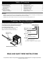
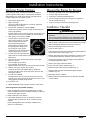
Customer Service Information
If you have questions or problems with installation, contact your
Dacor dealer or the Dacor Customer Assurance Team. When you
call, have ready the range’s model/serial numbers, which are on
the rating label through the grate inside the door (see below).
Dacor Customer Assurance Team
Phone: 833-35-ELITE (833-353-5483) USA, Canada
Mon – Fri, 5:00 a.m. to 5:00 p.m. Pacific Time
Website: www.dacor.com/customer-care/contact-us
Model Identification
HGPR48S/NG/H
SIZE (width in inches)
GAS TYPE
ALTITUDE
COLOR
NG = Natural Gas
LP = Liquid Petroleum (Propane)
H = Equipped for high altitude operation,
4000 ft. (1219 m) and up
No Character = Equipped for low altitude operation
C = Custom color
S = Stainless steel
Model/Serial Number Location
Model and serial
number label located
inside grill
Front panel,
below control
knobs
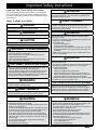
READ AND SAVE THESE INSTRUCTIONS

1
Important Safety Instructions
WARNING: TIPPING HAZARD
• Almost any-size person can tip the range and be killed.
• Install the anti-tip bracket as directed (Pg. 5).
• After moving the range, use a flashlight to verify that the anti-tip foot
engages the anti-tip bracket (Pg. 8).
• Failure to follow install the anti-tip bracket can lead to serious personal
injury or death if the range is tipped over.
AVERTISSEMENT: DANGER DE BASCULEMENT
• Presque toute personne de taille peut faire basculer la gamme et être tué.
• Installez le support antibasculement comme indiqué (pg. 5).
• Après avoir déplacé la cuisinière, utilisez une lampe de poche pour vérifier que
le pied antibasculement s’engage dans le support antibasculement (pg. 8).
• Ne pas suivre l’installation du support anti-basculement peut entraîner des
blessures graves ou la mort si la cuisinière est renversée.
WARNING
NEVER use the range as a space heater. Doing so may result in carbon
monoxide poisoning and overheat the range.
AVERTISSEMENT
N’utilisez JAMAIS la cuisinière comme chauffage d’appoint. Cela pourrait entraîner
un empoisonnement au monoxyde de carbone et surchauffer la cuisinière.
WARNING
Do not cover any part of the range with foil or other such items. Doing so
blocks air flow through the oven, may cause carbon monoxide buildup, and
may trap heat, causing a fire hazard.
AVERTISSEMENT
Ne recouvrez aucune partie de la cuisinière avec une feuille ou d’autres articles
de ce genre. Cela empêche l’air de circuler dans le four, peut provoquer une
accumulation de monoxyde de carbone et peut emprisonner la chaleur,
provoquant ainsi un risque d’incendie.
WARNING
Follow the information in this manual exactly to avoid property damage,
personal injury, or death.
• Do not store or use gasoline or other flammable vapors and liquids in the
vicinity of this or any other appliance.
• IF YOU SMELL GAS...
- do not turn on any appliances.
- do not use any phone in your building.
- immediately call your gas supplier from a neighbor’s home, and follow
the supplier’s instructions. (If you cannot reach your gas supplier, call
the fire dept.)
• Installation and service must be performed by a qualified installer, service
agency, or the gas supplier.
WARNING
Suivez les instructions de ce manuel pour éviter tout dommage matériel,
blessure corporelle ou mort.
• Ne stockez pas ou n’utilisez pas d’essence ou d’autres vapeurs et liquides
inflammables à proximité de cet appareil ou de tout autre appareil.
• SI VOUS SENTEZ DU GAZ...
- n’allumez aucun appareil.
- n’utilisez aucun téléphone dans votre immeuble.
- appelez immédiatement votre fournisseur de gaz de la maison d’un
voisin et suivez les instructions du fournisseur. (Si vous ne pouvez pas
joindre votre fournisseur de gaz, appelez le service d’incendie.)
• L’installation et l’entretien doivent être effectués par un installateur qualifié,
une agence de service ou le fournisseur de gaz.
CALIFORNIA PROPOSITION 65 WARNING
Burning gas cooking fuel generates by-products known by the State of
California to cause cancer and reproductive harm. Law requires California
businesses to warn customers of potential exposure to such substances. To
minimize exposure, operate the range as instructed in the user manual.
Important Info About Safety Instructions
The warnings throughout this manual cannot cover all possible
issues. Use common sense and caution in installing and testing
this range. Contact Dacor Customer Assurance about issues you
cannot resolve.
Safety Symbols and Labels
DANGER
Immediate hazards that WILL cause severe injury or death.
WARNING
Hazards/unsafe practices that COULD cause severe injury or death.
CAUTION
Hazards/unsafe practices that COULD cause minor injury or property damage.
• Read the User Manual before operating the range.
• Keep packaging material away from children.
• If you receive a damaged product, immediately contact your dealer; do not
install/use a damaged appliance.
• The range must be installed by qualified personnel as instructed in this manual.
• The owner should know the gas shut-off valve and electrical-outlet locations so
they can turn off the gas supply and power to the range as needed.
• Do not install a venting system that blows air down on the range. Ignition
and combustion problems may result, leading to injury/unintended operation.
• If the range is near a window, do not hang long curtains that may be blown
over the cooktop.
• Do not connect this range to the gas supply without first installing the
provided gas-pressure regulator.
• Do not climb anywhere on the range.
• Do not install/repair/replace any range parts unless as instructed in the
provided manuals. A qualified technician should perform all other service.
• Make sure all cooktop parts are dry before lighting a burner.
• The range is designed for home use; commercial use is not warrantied; do
not install the range in a mobile home or RV.
• Do not leave children/pets unattended near the range.
• Do not let children play with any part of the range.
• The range’s 3-prong grounding plug protect against electric shock. Plug
it in a dedicated, grounded 3-prong outlet. The owner shall ensure the
proper outlet is installed. Do not:
- remove the third (ground) prong from the power plug.
- use an adapter plug or an extension cord.
- use a damaged power cord.
- use a ground fault interrupter (GFI).
WARNING
WARNING

2
WARNING
• IMPORTANT: Observe all governing codes and ordinances
during planning and installation. Contact your local building
department for further information.
• To prevent an electric shock hazard, the power supply
must meet the specifications stated below. It is the owner’s
responsibility to make sure that the electrical service meets
electrical requirements and that the electrical outlet has
been properly installed by a licensed electrician.
The appliance installation must be electrically grounded in
accordance with local codes or, in the absence of local codes,
with the National Electrical Code, ANSI/ NFPA 70:
Electrical Requirements
• The range is supplied with a factory installed, 6 foot long, power
cord with a three-prong grounding plug. It is connected to the
chassis at the rear of the range. It must be connected to a
dedicated, grounded three-prong electrical outlet.
• The correct voltage, frequency and amperage must be supplied
to the appliance from a separate, grounded, circuit that is
protected by a properly sized circuit breaker or time delay fuse.
Model Circuit Required Total Connected Load*
HGPR36S
120 Vac, 60 Hz, 15 Amp.
120 Vac 60 Hz,
5.0 Amp.
HGPR48S
120 Vac, 60 Hz, 15 Amp.
120 Vac 60 Hz,
8.0 Amp.
*These specifications for reference only. Refer to the rating label for exact specifications
(see below for location).
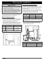
Planning the Installation
Gas-Supply Requirements
• Installation of this range must conform to local codes or, in their
absence, to the National Fuel Gas Code, ANSI Z223.1/NFPA 54.
• The range being installed must match the home gas service
(natural or LP gas).
• If using the range above 4000 ft. (1219 m) altitude, ensure it is
equipped for high-altitude use. See the rating label and graphic
on the inside front cover to verify the correct model.
• This table has gas-supply pressure requirements:
GAS-SUPPLY PRESSURE REQUIREMENTS*
Gas Type Min. Manifold Pressure
Minimum Gas-Supply
Pressure**
Natural Gas 5” Water Column 6” Water Column
Liquid Propane (LP) 10” Water Column 11” Water Column
*The gas supply pressure for testing the regulator setting shall be at least 1 inch
water column (249 Pa) above the specified manifold pressure’ **maximum gas supply
pressure for all models: 1/2 psi.
The ratings above are for reference only. See the rating label for exact specifications.
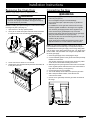
• Use only the factory-installed regulator. The regulator inlet
receives a 3/4” gas line. The range ships with a 1/2”-to-3/4”
adapter connected to the regulator.
B
A
Power
cord
Gas
Inlet
GAS-/ELECTRICAL-ACCESS DIMENSIONS
Model A B
HGPR36S
13 1/16” to 14 3/8” (33.2 to 36.5 cm) 7 5/16” (18.6 cm)
HGPR48S
13 1/16” to 14 3/8” (33.2 to 36.5 cm) 4 1/4” (10.8 cm)
Rating
Label

3
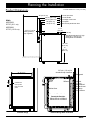
Planning the Installation
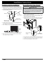
48” (121.9 cm)
Front of open door
Front of handle
Front edge of bull nose
Front panel
Rear of front panel/oven door
28 1/2” (72.4 cm)
(91.9 cm)
36 3/16”
(95.3 cm)
37 1/2”
26 7/8” (68.3 cm)
26” (66.0 cm)
24” (61.0 cm)
1 1/4”
(3.2 cm)
to
1 1/16” (2.7 cm) to
cooking surface
(top of grates)
Standard backguard is 3” high.
Optional 1.5” and 9” high
backguards are available.
3” (7.62 cm)
24” (61.0 cm)
Cabinet face
lines up with
back of control
panel
Product tolerances: ±1/16” (±1.6 mm)
Product Dimensions
Width
HGPR36S:
35-7/8” (91.1 cm)
HGPR48S:
47-7/8” (121.6 cm)
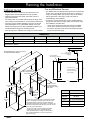
Installed Range With DowndraftInstalled Range
3/8” min. (1.0 cm) for
downdraft cap clearance
Back of
control
panel
Cabinet face
Downdraft Part Numbers
ERV3015 (for 30G)
ERV36-ER (for 36G)
ERV48-ER (for 48G)
Stiffener
3/8” min.
(1.0 cm)
space behind
downdraft vent
chassis to
clear stiffener
Countertop
Backguard
Downdraft Part Nos.
ERV36-ER for HGPR36S
ERV48-ER for HGPR48S

4
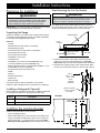
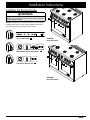
Planning the Installation
DIMENSIONS
Model F G H I J
HGPR36S 42” (106.2 cm)*; 36” (91.4 cm)** 36” (91.4 cm)** 33 1/2” (84.8 cm) 30 7/8” (78.4 cm) 3 1/2” (8.9 cm)
HGPR48S 54” (137.2 cm)*; 48” (121.9 cm)** 48” (121.9 cm)** 43 1/2” (110.2 cm) 29 7/8” (75.9 cm) 3” (7.6 cm)
* Recommended ** Minimum
Note 2
F
G
2
Cabinet/countertop depth is at discretion of customer but
cabinet face MUST NOT protrude further than rear of front
panel, see product dimensions.
3
Consult local code for exact location requirements.
1
Vertical from range grate level to combustible overhead
surface; if installing an overhead vent hood, also check
hood specifications for minimum required clearances.
4
Vertical from grate level to combustible surface.
Non-combustible
surface along back wall
recommended
10” (25.4 cm) min.
to combustible side
walls above the range
(both sides)
30” (76.2 cm)
min.
1
37 1/2”
(95.3 cm)
max.
13” (33.0 cm)
max.
5
15” (38.1 cm)
min.
4, 5
5
This specification does not apply for cabinets more
than a horizontal distance of 10” (25.4 cm) from the
edge of the range.
Suggested
location of
utilities
3
Grate
level
G
10" (25.4 cm) min.
to combustible side
walls above the range
(on both sides)
non-combustible
rear wall (recommended)
H
Backsplash
3/8" (1.0 cm)
min. for downdraft cap
clearance
J
Note 2
Cutout tolerances: +1/16” (+1.6 mm),
-0 unless otherwise stated
Range Downdraft Vent
HGPR36S ERV36-ER
HGPR48S ERV48-ER
Range 1.5” Low-Profile Backguard
HGPR36S APB36GLP
HGPR48S APB48GLP
Cabinet Layout
• All maximum/minimum dimensions and clearances in the
diagrams below must be maintained for safe operation.
• Install the range away from drafts, and include a hood or
approved downdraft.
• For safety’s sake, do not install cabinets above the range; other-
wise, install a hood that extends 5” or more past the cabinet face.
• The range may be installed against the rear wall. You should
install a backguard or non-combustible material on the wall
between the range and hood. Non-combustible material is not
needed behind the range from countertop to floor.
• Seal openings in the wall behind the range or in the floor below.
Gas and Electrical Service
• The shaded area in the diagram below shows the recommended
location of the gas inlet and the electrical outlet. (If replacing a
range, the existing utilities may be used if they do not interfere
with the placement of this range. Check local codes for
permissible gas-valve locations.)
• An external, manual shut-off valve must be installed between
the gas inlet and range so the gas supply can be turned on/off
• The installation must also allow:
- access to the gas shut-off valve when the unit is installed.
- access to the electrical outlet, when the range is in place.
- the range to be pulled out for service without disconnecting
the gas and electrical supply.

5
Floor-Mounting the Anti-Tip Bracket
WARNING
The anti-tip bracket must be attached as instructed to the concrete
slab or wood sub-floor below any flooring (including cement
board). Do not attach the bracket directly to floor coverings.
Four plastic anchors are provided with three sizes (4 each) of
#8 or #12 Phillips-head screws. Use the anchors and four of the
screws only if attaching the bracket to a concrete sub-floor.
1. Determine the location of the range center line and front
panel for the range’s final position based on the Product
Dimensions (Pg. 5) and the actual cabinet/cutout dimensions.
2. Determine the required position of the anti-tip bracket. Mark
the four (4) mounting hole locations on the floor with a pencil.
Preparing for Installation
WARNING
• If the home gas/electric service does not meet product
specifications, postpone installation until the gas supplier/
licensed electrician makes the appropriate modifications.
• Before installing the range, install the anti-tip bracket.
IMPORTANT: In the Commonwealth of Massachusetts, the range
must be installed by a licensed plumber or gas fitter.
Unpacking the Range
Unpack the parts box, and verify that all components are present.
If anything is missing/damaged, contact your dealer immediately.
Do not install a damaged/incomplete range.
Parts List
- 3 Grates
- 8 Standard burner caps (4 brass, 4 porcelain)*
- 4 Standard burner rings
- 4 SimmerSear burner caps (2 brass, 2 porcelain)*
- 2 SimmerSear burner rings
- 2 SimmerSear burner heads
- 2 GlideRack™ oven racks
- 1 Standard rack
- 2 GlideRack™ 18” wide oven racks (RNRP48G only)
- 1 18” wide standard oven rack (HGPR48S only)
- Knobs (4 Standard cooktop, 2 cooktop MAX GRIDDLE, 1 oven
for HGPR36S, 2 oven for HGPR48S)
- Anti-tip bracket with screws and anchors
- Griddle
- Wok ring
- Stainless steel cleaner
- Literature kit
- Broiler pan/grill
*Two types of burner caps are provided to suit customer
preference. Brass discolors with use; performance is unaffected.
Installing a Backguard (Optional)
Before making the gas/electrical connections, install the backguard
per backguard kit instructions. Approved kits for this range:
Model Description
APB36D9 9” high backguard for range model HGPR36S
APB48D9 9” high backguard for range model HGPR48S
Installation Instructions
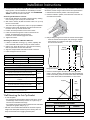
Installing the Anti-Tip Bracket
Install the anti-tip bracket in one of two ways:
• Floor mounting (preferred)
• Wall mounting (alternate—if floor mounting is unsuitable). If the
range’s front panel (excluding bull nose) is over 27” (68.6 cm)
from the back wall – or – if the flooring is too thick (see Wall-
Mounting the Anti-Tip Bracket), floor-mounting must be used.
Sub-floor
Screws threaded
into anchors
Anti-tip bracket
Floor
covering
Anchor
C
L
B
Anchor, 4 places:
use for concrete
floor only
Range
center line
Range front
panel*
TOP VIEW
#8 x 1”
#8 x 1 1/4” or
#12 x 1 3/4
screw,
4 places
(see text)
A

6
Using the graphic in Step 4 and the final installation cabinet/cutout
dimensions, find the range’s center line and front panel location.
1. Determine and mark the position of the anti-tip bracket.
2. Place the bracket in position, and mark a dot at the notch on
each side of the bracket.
3. Drill just deep enough to see if the bit contacts the base plate.
- If the bit contacts the base plate, wall mounting is suitable.
- If the bit does not contact the base plate, you must either
floor-mount the bracket.)
4. Place the bracket against the wall in the mounting location.
Using a 1/8” bit, drill four 1-5/8” deep pilot holes perpendicular
to the screw-seating surfaces shown below. Attach the bracket
to the wall as shown with the included #12 x 1-3/4 screws.
ANTI-TIP BRACKET PLACEMENT
Dimension HGPR36S HGPR48S
C 11-7/8” (30.2 cm) 2-1/2” (6.4 cm)
*Excludes bull nose (see Pg. 3)
3. Determine the screw size required. The minimum full thread
depth (portion of screw threaded into wood/slab) for wood is
3/8” (1 cm) and 5/8” (1.6 cm) for concrete. See SCREW SIZE
TABLE to select the correct screw size.
Anchoring the Bracket To Concrete
1. Drill four 3/8”-diameter countersink holes through any existing
floor covering to (but not into) the concrete slab.
2. With a 3/16” masonry bit, drill four anchor holes 1-1/4” (3.2 cm)
into the concrete slab.
The hole must be longer than the anchor for proper installation.
3. Clear the holes of dust and debris, then tap the anchors into
the holes so the top is flush with the slab.
4. Position the anti-tip bracket over the anchor holes.
5. Insert the screws through the 4 holes in the base of the
bracket, and thread them into the anchors.
Ensure the screw threads engage the anchor.
6. Tighten the screws.
Attaching the Bracket To a Wooden Sub-Floor
1. If there is a hard floor covering (e.g., ceramic, asphalt), drill
four countersink holes to (but not into) the wood sub-floor.
2. (With a 1/16” bit for #8 screws or a 1/8” bit for #12 screws)
Drill four pilot holes into the wood sub-floor.
3. Align the anti-tip bracket holes with the holes in the floor.
4. Insert and tighten the four screws.
ANTI-TIP BRACKET PLACEMENT
Dimension HGPR36S HGPR48S
A 10-7/8” (27.6 cm) 1-1/2” (3.8 cm)
B 22-1/2” (57.2 cm) 22-1/2” (57.2 cm)
*Excludes bull nose (see Pg. 3)
SCREW SIZE TABLE
Sub-Floor Type/Floor Covering Thickness Screw
Concrete or wood sub-floor, no floor covering
#8 x 1*
Concrete/wood sub-floor, floor covering up to ¼” thick
Concrete/wood sub-floor, floor covering over ¼”, up to
½” thick
#8 x 1 ¼ *
Wood sub-floor, floor covering over ½”, up to 1 3/16” thick #12 x 1 ¾ *
Concrete under floor covering over ½” thick
Not
included**
Wood sub-floor, floor covering over 1-3/16” thick
*Included with range; **Determine required depth based on information in
Step 3 and purchase from local hardware store.
Wall-Mounting the Anti-Tip Bracket
• To use this option:
- the range’s front panel (exterior surface of the door—not the
forward edge of the bull nose) must be 27 in. (68.6 cm) or
less from the wall behind the range.
- the bracket screws must be able to thread into the wall’s base
plate (see the graphic, Step 5, Pg. 7).
• Notches on the bracket sides indicate the minimum required
height of the base plate and that any floor covering does not
keep screw threads from engaging the base plate.
Installation Instructions
Range
center line
C
L
C
L
Bracket
center
line
Range front panel*
C
Wall
Stud
Base
plate
Drywall

7
Installation Instructions
Removing the Oven Door
Make the range easier to move by detaching the door.
WARNING
• Do not try to disengage the hinge catches with the door
removed. The springs could release causing personal injury.
• Do not lift the door by its handle.
NOTE: If installing the optional backguard, install it before sliding
the range into place. (See page 5.)
1. Open the door to its fully opened position.
2. Use a pair of needle nose pliers and a flat blade screwdriver
to rotate the catch over the retaining arm on each hinge.
3. Lift the oven door to about 15° from vertical.
4. Grasping the door with both hands just below the handle, lift
it away from the oven.
Catch
Retaining arm
Connecting the Gas
WARNING
• Close the gas-supply valve, and unplug the range before
connecting the gas line.
• Do not overtighten the gas connections/fittings.
• Do not use Teflon tape or plumber’s putty on gas flex line
connections.
• LP installations: The LP gas tank must have its own high-
pressure regulator in addition to the range’s own regulator.
• The maximum gas-supply pressure to the regulator must
never exceed 1/2 psi (pound/square inch) or 3.5 kPa.
• Disconnect the range and shut-off valve from the gas supply
piping for pressure tests over 1/2 psi (3.5 kPa).
• The shut-off valve must be closed during pressure testing at
or below 1/2 psi (3.5 kPa).
• Check all gas lines for leaks as instructed to avoid a fire or
explosion hazard. Do not use a flame to check for leaks.
NOTE: The gas-pressure regulator is factory-set the type of
gas intended for use with the range. To verify that the range is
compatible with the home gas supply, see the range rating label
(rear of range). If the range should use LP gas, “LP” will be in the
model number. Call your dealer if the range is incompatible with
the home gas supply.
1. Close the gas-supply valve, and unplug the range.
2. Connect a flexible gas line to the gas shut-off valve previously
installed on the stub out.
The gas line must be long enough for the range to be pulled
out for service without disconnecting the flex line.
3. Slide the gas line up through the access holes in the chassis
to the regulator. (Move aside the wires in the access holes to
keep them from catching on the gas line.)
4. Connect the gas line to the regulator.
5. Turn off all cooktop control valves, and open the gas valve.
6. With a soap-and-water solution, check all lines and
connections for leaks.
7. (If there are no gas leaks) Close the gas valve connected to
the range.
Regulator
connection

8
Installation Instructions
Finalizing Anti-Tip Installation
1. Peel the protective plastic from the range (including the door).
2. Measure from floor to countertop, and adjust the leveling legs as
needed so the cooktop trim is even with or above the countertop.
3. Find the anti-tip foot on the back of the range, and turn it until
it is 1/16” (2 mm) off the floor.
4. Carefully slide the range into the cutout, ensuring the anti-tip
foot engages the anti-tip bracket.
5. With a flashlight, verify that the bracket covers the anti-tip foot.
6. With a level ensure the range tnot tilt front to back or side to
side. (Adjust the legs as needed.)
Re-installing the Oven Door(s)
WARNING
To avoid personal injury or property damage:
• Before opening the door, ensure the notch on the bottom of
each hinge rests on the lower lip of each hinge receptacle.
• Flip the hinge locks toward the range immediately after
installing the door.
1. Grasp the oven door on the sides below the handle, and hold
it at a 15° angle to the oven front.
2. Slide the hinges into their openings, resting the bottom of the
hinge arms on the hinge receptacles.
3. Keeping the door at 15°, push until the notch on the bottom of
each hinge slips over the lower lip of each hinge receptacle.
4. Fully open the door, and flip both hinge locks toward the oven.
5. Carefully open/close the door fully to verify proper installation.
6. Remove any packaging from inside the oven.
Lower lip of
hinge receptacle
Notch on bottom
of hinge
Anti-tip
bracket
Anti-tip foot
up
down
Back of range
Anti-Tip Foot
(location varies)
1 1/4” *
* Distance to floor:
4 1/16” to 5 5/16”
Rear leg

9
Installing the Burner Knobs
WARNING
Incorrectly installing the burner-control knobs may lead to griddle
damage from excessive heat. Knobs for the center burners have
the MAX GRIDDLE setting.
NOTE: A D-shaped key on the back of each knob mates with the
D-shaped valve stem to ensure proper installation and function
The range has three types of burner-control knobs:
Installation Instructions
B
A
C
C
C
C
C
C
C
C
B
B
A
A
B
HGPR36S
Knob Placement
HGPR48S
Knob Placement
BROIL500 °400 °300 °200°WARM CLEAN
Oven / Broil Knob A
Left Burner Knob Icons C
Max Griddle Burner Knob Icons B

10
Installation Instructions
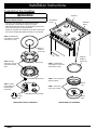
Assembling the Cooktop
WARNING
Do not use the cooktop unless all burner components and
grates are properly in place.
• The range uses standard and SimmerSear burners.
• Use porcelain or brass burner caps as you prefer.
• When assembling the burners, rotate/adjust each part until it
seats securely in place for proper function.
• Gently set the grates in the spill tray so the feet of each grate
rest in their corresponding dimples formed into the spill tray.
Standard Burner Installation
STEP 1: Put burner
ring on top of head.
STEP 2: Turn ring until it
drops into place.
STEP 3: Install burner
caps. Ridge on cap must
surround top of ring.
Burner
head
Burner
ring
Ridge on
bottom of
burner cap
SimmerSear
burner
Standard
burner
Spill tray
SimmerSear Burner Installation
STEP 1: Install
burner head. Put
locating tab in
keyed hole.
STEP 2: Install
burner ring. Line up
ring tabs with head
slots.
STEP 3: Install burner
cap. Ridge on cap must
surround top of ring.
Burner ring
Burner base
Burner head
Ridge on
bottom of
burner cap
Keyed
hole

11
Installation Instructions
Installation Instructions
Verifying Proper Function
Before using the range, read the User Manual completely. It
contains important safety, service, and warranty information.
Before starting, turn off all range controls, and verify that all
cooktop components are properly in place..
1. Open the gas-supply valve.
2. Plug in the range.
The oven indicator light blinks for 10 seconds. (When the
blinking stops, go to Step 3.
3. Test a burner: Pushing-turn a knob to HIGH.
The burner may take 4 seconds to ignite, at which time the
ignitor stops sparking.
If ignition does not occur within 4 seconds, turn the burner off,
wait 5 minutes for the gas to dissipate, then repeat Step 3.
4. After ignition, turn the knob to LOW.
A proper flame is steady and quiet,
with a sharp, blue inner cone that
varies in length with the burner
size. Dacor’s Smart Flame™
feature reduces the flame under
the grate fingers to lengthen the
life of the grate. If the range is
equipped for LP gas, the flame tips
may be yellow, which is normal.
5. Turn the burner off, and repeat the
ignition test for the other burners, being sure to turn each off
after testing.
6. Open the oven door. On the control panel, turn the light
switch on and off.
The oven lights go on and off.
7. Turn on/off the convection fan.
Behind the filter in the oven’s rear wall, the fan whirs and stops.
8. With the door open, turn the oven to 400 °F.
The knob and oven’s ON indicator light up. Within 60
seconds, the bake burner (in the oven floor) comes on and
starts giving off heat.
9. Turn the oven to BROIL.
The bake burner turns off. The oven knob and oven’s ON
indicator are lit; within 60 seconds the IR burner (on the oven
ceiling) ignites and starts giving off heat.
10. Turn off the oven.
11. (Model HGPR48S) Verify the proper function of both ovens.
If the range does not operate properly:
1. Check the electrical connections and gas supply to ensure
that the installation has been completed correctly, and that the
range receives power and gas..
2. Retest cooktop and oven function.
3. If the rangee still does not work, contact Dacor Customer
Assurance (833) 353-5483. Do not try to repair the range
yourself.
Product damage/failure due to improper installation and
service is not warrantied.
Moving the Range for Service
1. Close the gas-supply valve, and unplug the range.
2. Pull the range out from the wall.
3. Perform the needed service/maintenance.
4. Push the range back into place, being sure to engage the
anti-tip bracket (see Pg. 8).
5. Plug in the range, and open the gas-supply valve.
Installation Checklist
WARNING
• To the installer: Complete this checklist to verify thorough
installation.
• To the owner: Proper installation is your responsibility. Make
sure all installation work is performed by qualified personnel.
F Was the plastic coating removed from the outside of the range?
F Were all packaging materials removed from the oven?
F Were all leveling legs lowered to the floor?
F Is the unit level? (Pg. 8.)
F Is the range secured with the provided anti-tip bracket and foot
as instructed in this manual? (Pgs. 5, 8.)
F Was the gas-supply inlet pressure measured to ensure it does
not exceed the maximums specified in this manual. (Pg. 2.)
F Is the range connected to the gas supply as instructed and
according to applicable codes?
F Was the gas supply checked for leaks?
F Is the oven door properly installed? (Pg. 9.)
F Were the burner knobs properly installed? (Pg. 9.)
F Are the burners properly assembled and grates properly
installed? (Pg. 10.)
F Was proper function verified?
F Was the warranty activated online or the warranty card filled
out and mailed?
Proper
Flame

NotesNotes

Notes

Dacor ● 14425 Clark Avenue, City of Industry, CA 91745 ● Phone: (800) 793-0093 ● Fax: (626) 403-3130 ● www.dacor.com
-
 1
1
-
 2
2
-
 3
3
-
 4
4
-
 5
5
-
 6
6
-
 7
7
-
 8
8
-
 9
9
-
 10
10
-
 11
11
-
 12
12
-
 13
13
-
 14
14
-
 15
15
-
 16
16


Dacor HGPR48S/LP/H Guide d'installation
- Catégorie
- Fours
- Taper
- Guide d'installation
- Ce manuel convient également à
dans d''autres langues
Documents connexes
-
Dacor HGR30PSLP Guide d'installation
-
Dacor HGER30SLP Guide d'installation
-
-
Dacor HGPR30S/NG Guide d'installation
-
Dacor Heritage Induction Pro Range Guide d'installation
-
-
Dacor HDPR48CLP Guide d'installation
-
-