GE ZIBI240HII Guide d'installation
- Catégorie
- Frigos
- Taper
- Guide d'installation

INSTALLATION
INSTRUCTIONS
with Design Guide
Fresh-Food Refrigerator
Bar Refrigerator with Icemaker
Monogram.com

2 31-51544-10
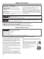
Safety Information
BEFORE YOU BEGIN
Read these instructions completely and carefully.
•
IMPORTANT – Save these instructions for
local inspector’s use. Observe all governing codes and
ordinances.
• Note to Installer – Be sure to leave these instructions
with the Consumer.
• Note to Consumer – Keep these instructions with your
Owner’s Manual for future reference.
If you received a damaged refrigerator, you should
immediately contact your dealer or builder.
Skill Level – Installation of this refrigerator requires
basic mechanical, carpentry and plumbing skills. Proper
installation is the responsibility of the installer. Product
failure due to improper installation is not covered under
the GE Appliance Warranty. See the Owner’s Manual for
warranty information.
WARNING
Explosion Hazard. Keep flammable materials and vapors, such as gasoline, away from
refrigerator. Failure to do so can result in fire, explosion, or death.
WARNING
To reduce the risk associated with choking, do not allow children under 3 years of age to have
access to small parts during the installation of this product.
For Monogram local service in your area, call 800.444.1845 or visit monogram.com.
For Monogram service in Canada, call 888.880.3030
For Monogram Parts and Accessories, call 800.444.1845 or visit monogram.com.
For Monogram Parts and Accessories in Canada, call 888.880.3030 or visit monogram.ca.
CONNECTING ELECTRICITY
WARNING
Electrical Shock Hazard.
Plug into a grounded 3-prong outlet.
Do not remove the ground prong.
Do not use an adapter.
Do not use an extension cord.
Failure to follow these instructions can result in death, fire, or electrical shock.
Do not, under any circumstances, cut or remove the third (ground) prong from the power cord.
For personal safety, this appliance must be properly grounded.
The power cord of this appliance is equipped with a
3-prong (grounding) plug which mates with a standard
3-prong (grounding) wall outlet to minimize the possibility
of electric shock hazard from this appliance.
Have the wall outlet and circuit checked by a qualified
electrician to make sure the outlet is properly grounded.
Where a standard 2-prong wall outlet is encountered, it
is your personal responsibility and obligation to have it
replaced with a properly grounded 3-prong wall outlet. Do
not use an adapter.
The refrigerator should always be plugged into its own
individual electrical outlet which has a voltage rating that
matches the rating plate.
A 115 Volt AC, 60 Hz, 15- or 20-amp fused, grounded
electrical supply is required. This provides the best
performance and also prevents overloading house wiring
circuits which could cause a fire hazard from overheated
wires.
Never unplug your refrigerator by pulling on the power
cord. Always grip plug firmly and pull straight out from the
outlet.
Immediately discontinue use of a damaged
supply cord. If the supply cord is damaged
it must be replaced by a qualified service
professional with an authorized service part
from the manufacturer.
When moving the refrigerator away from
the wall, be careful not to roll over or
damage the power cord.

31-51544-10 3
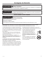
Consignes de Sécurité
AVERTISSEMENT
Risque d’explosion.
Conservez les matériaux et vapeurs inflammables tels que l’essence à l’écart de votre réfrigérateur. Le non-respect de
cette instruction peut entraîner un risque d’incendie, d’explosion ou de décès.
AVERTISSEMENT
Pour réduire le risque d’étouffement pendant l’installation de ce produit, ne pas laisser les
petites pièces à la portée des enfants âgés de moins de 3 ans.
AVERTISSEMENT
Risque d’électrocution.
Branchez l’appareil dans une prise à 3 broches mise à la terre.
N’enlevez pas la broche de mise à la terre.
N’utilisez pas un adaptateur.
N’utilisez pas un cordon de rallonge.
Le non-respect de ces instructions peut entraîner des risques d’incendies, des chocs électriques ou la mort.
BRANCHEMENTS ÉLECTRIQUES
Ne coupez pas ou n’enlevez pas, sous aucun prétexte, la troisième broche de mise à la terre du cordon
d’alimentation. Pour des raisons de sécurité, cet appareil doit être correctement mis à la terre.
Le cordon d’alimentation de cet appareil est équipé d’une
fiche à trois broches (pour une mise à la terre) qui s’adapte
à la prise de courant standard à 3 broches (pour une mise
à la terre) pour minimiser les risques de chocs électriques
par cet appareil.
Faites vérifier la prise murale et le circuit électrique par
un électricien qualifié pour s’assurer que le système est
correctement mis à la terre.
Dans le cas d’une prise biphasée, l’installateur a la
responsabilité et l’obligation de la remplacer par une prise
triphasée correctement mise à la terre. N’utilisez pas
d’adaptateur.
Le réfrigérateur doit toujours être branché à sa propre
prise électrique d’une tension nominale correspondant à
celle indiquée sur sa plaque signalétique.
Une alimentation électrique à 115 volts CA, 60 Hz, avec
un fusible de 15 ou 20 ampères et une mise à la terre est
nécessaire. Ceci permet d’obtenir un meilleur rendement
et évite de surcharger les circuits électriques du domicile
qui risque d’occasionner un incendie en surchauffant.
Ne débranchez jamais le réfrigérateur en tirant sur le
cordon d’alimentation. Prenez toujours fermement la fiche
en main et tirez pour la sortir de la prise.
Cessez immédiatement l’utilisation d’un
cordon électrique endommagé. Si le
cordon électrique est endommagé, son
remplacement doit être exécuté par un
technicien en réparation qualifié au moyen
d’un cordon de rechange autorisé par le
fabricant.
Lorsque vous éloignez votre réfrigérateur
du mur, faites attention à ne pas le faire
rouler sur le cordon d’alimentation afin de
ne pas l’endommager.

4 31-51544-10
CARING FOR YOUR STAINLESS
STEEL
• Before installation or first use, we strongly advise that
you polish the stainless steel exterior and handle with
a commercially available stainless steel cleaner such
as Stainless Steel Magic.™ To preserve and protect
the fine finish, we also strongly advise that you apply
stainless steel cleaner monthly.
STAINING WOOD DRAWER FRONTS
The drawer fronts are unfinished cherry wood. During
use, oil from hands may accumulate and stain the
wood.
• The drawer fronts may be stained and sealed to
match adjacent cabinetry.
• Apply the stain and sealer according to the
manufacturer’s instructions. To avoid unpleasant odor,
keep the door open to ventil ate and allow the stain/
sealer to dry completely before using the product.
CONTENTS
Important Information .................................................2
Parts Required ..............................................................4
Caring for Your Stainless Steel .....................................4
Tools, Hardware ...........................................................4
Staining Wood Drawer Fronts ......................................4
Install Water Line .........................................................5
Design Guide (For ZIFS240 and ZIBS240)
The Installation Space ...................................................6
Side-by-Side Installations .............................................7
Product Clearances .......................................................7
Design Guide (For ZIFI240 and ZIBI240)
The Installation Space ...................................................8
Side-by-Side Installations .............................................8
Product Clearances .......................................................8
Installation Instructions
Step 1, Remove Packaging and Installation Parts ........9
Step 2, Reversing the Door (ZIFI240 models only) ......9
Step 3, Install Custom 3/4” Door Panel and Handle
(ZIFI240 and ZIBI240 models only).............................12
Step 4, Leveling...........................................................13
Step 5, Connect Water Supply
(ZIBI240 and ZIBS240 models only) ...........................13
Step 6, Connect Power ...............................................14
Step 7, Slide Product into Cutout ................................14
Step 8, Set Temperature Controls ..............................14
TOOLS/HARDWARE REQUIRED
• Adjustable wrench
• Carpenter’s glue (ZIFI240 and ZIBI240 models only)
• Screwdriver (ZIFI240 and ZIBI240 models only)
ZIFI240 AND ZIBI240 MODELS ONLY
PARTS REQUIRED
• Custom handle
• Assembled overlay panel
• Screws
PARTS SUPPLIED
• Handle side trim
• Optional black or
stainless steel toekick
Installation Instructions
REFRIGERATOR/FREEZER
LOCATION
Ŷ Do not install the refrigerator/freezer where the
temperature will go below 55°F (13°C). It will not run
often enough to maintain proper temperatures.
Ŷ Do not install the refrigerator/freezer where
temperatures will go above 100°F (37°C). It will not
perform properly.
Ŷ Do not install the refrigerator/freezer in a location
exposed to water (rain, etc.) or direct sunlight.
Ŷ Install it on a floor strong enough to support it fully
loaded.

31-51544-10 5
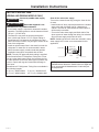
INSTALL WATER LINE
(ZIBI240 AND ZIBS240 MODELS ONLY)
WARNING
Connect to potable water supply
only.
AVERTISSEMENT
Raccordez l’appareil à une
alimentation d’eau potable seulement.
• A cold water supply is required for automatic icemaker
operation. The water pressure must be between 20 and
120 p.s.i. (137-827 kPa).
• The water line can enter the opening through the
floor or back wall. Route 1/4” O.D. copper tubing or
SmartConnect™ kit between the cold water line and
water connection location, long enough to extend to the
front of the refrigerator.
• Install an optional water filter in the water line near the
refrigerator. A water filter is recommended in areas
where the water supply contains sand and particles.
Installation Instructions are packed with the filter.
NOTE: The only GE approved plastic tubing is supplied
in the SmartConnect™ Refrigerator Tubing kits. Do not
use any other plastic water supply line because the line
is under pressure at all times. Other types of plastic may
crack or rupture with age and cause water damage to
your home.
SmartConnect™ Refrigerator Tubing Kits are available in
the following lengths:
ƍP:;; ƍP:;;
ƍP:;; ƍP:;;
Shut off the main water supply.
Turn on the nearest faucet long enough to clear the line
of water.
• Install a shut-off valve (required) between the icemaker
water valve and cold water pipe in a basement or
cabinet. The shut-off valve should be located where it
will be easily accessible.
• Turn on the main water supply and flush debris. Run
about a quart of water through the tubing into a bucket.
Shut off water supply at the shut-off valve.
NOTE: Saddle type shut-off valves are included in many
water supply kits, but are not recommended for this
application.
NOTE: Commonwealth of Massachusetts Plumbing Codes
248CMR shall be adhered to. Saddle valves are illegal and
use is not permitted in Massachusetts. Consult with your
licensed plumber.
Floor
Water Line
Shaded Area
1-1/2"
min.
1/2"
9"
max.
10-1/2"
Water Line
Installation Instructions

6 31-51544-10
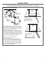
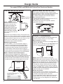
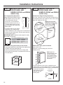
THE INSTALLATION SPACE
* For a standard installation: The product must be installed
so that the stainless steel front will project 1-5/8” forward of
adjacent cabinets. This position will allow a full door swing
and prevent interference with adjacent cabinetry. The opening
between cabinets must be 23-3/4” minimum.
** For a flush installation: Install a 1/4”-wide filler strip on the
hinge side. The filler strip will act as a spacer between the
door case and adjacent cabinets and will prevent interference
with the cabinet door swing. Recess the filler strip 1-5/8” back
from the front face of the refrigerator, or even with the front
edge of the product case (behind the gasket). The width of the
opening must be 24” (including the 1/4” filler strip).
• All models may be used freestanding.
Additional Specifications
• A 120 volt 60Hz., 15 or 20 amp power supply is
required. An individual properly grounded branch circuit
or circuit breaker is recommended. Install a properly
grounded 3-prong electrical receptacle recessed into
the back wall as shown. Electrical must be located on
rear wall as shown. NOTE: GFCI (ground fault circuit
interrupter) is not recommended.
For models ZIFS240 and ZIBS240 with Stainless Steel Doors and Handles
NOTE:
Handle and
handle standoff
depth is 2-1/4”.
NOTE:
Water line location
for ZIBS240 model
only
Design Guide
These products will fit flush to
adjacent cabinets when installed
with a 1/4” filler panel or cleat. The
filler panel should be recessed or
set back behind the door and even
with the front edge of the product
case.
Flush
Installation
Filler panel or cleat to be set
back even with front of case.
Front edge of product case
Front face
1/4”
110°
120°
CABINET CABINET
In a standard installation, the
product will project forward of
adjacent cabinets. See Dim. A.
Product Dim. A
ZIFS240 1-5/8”
ZIBS240 2-5/8”
Standard
Installation
Front edge of product case
Front face
CABINET CABINET
110°
120°
Dim. A

31-51544-10 7
PRODUCT CLEARANCES
The Fresh-Food Refrigerator or Bar Refrigerator with
Icemaker is factory set for a 110° door swing.
When installed in a corner:
• Allow 14” minimum clearance on the hinge side for a
full 110° door swing.
• Allow 4” min. clearance on the hinge side for the 90°
door swing and to allow racks to slide out.
NOTE: Clearances are based on the recommended
2-1/4” handle standoff depth.
NOTE: Right-hand models illustrated. Allow the same
clearances on the opposite side for left-hand fresh food
models ZIFI240 and ZIFS240 only. Models ZIBI240 and
ZIBS240 are not available with left-hand door swing.
• Test the door swing. Carefully open and close the
door. The door should not rub or catch on adjacent
cabinetry.
Choose the location:
• These products may be closed in on the top and
three sides as long as the front is unobstructed for air
circulation and proper access to the door.
• Do not install these products where the temperature
will go below 55°F (13°C) or above 100°F (37°C).
• These products are not designed to be stacked one
over the other.
7
14" Minimum to Wall
110
110 Door
Swing
21-5/8"
23-5/8"
4" Minimum to Wall
90
90 Door
Swing
For models ZIFS240 and ZIBS240 with Stainless Steel Doors and Handles
Design Guide
SIDE-BY-SIDE INSTALLATIONS
For a complete refreshment center, install a Fresh-
Food Refrigerator beside a Double-Drawer Refrigerator,
Beverage Center or Wine Chiller/Wine Reserve.
Or, install a Refrigerator with Icemaker beside a
Wine Chiller/Wine Reserve.
• A side-by-side installation requires at least a 47-1/2”-
wide minimum opening for standard installation and
48”-wide minimum opening for flush installation. No
trim kits required.
• Products must operate from separate, properly
grounded receptacles.

8 31-51544-10
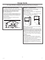
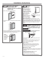
THE INSTALLATION SPACE
The product must be installed so that the custom panel front will
project 2-3/4” forward of adjacent cabinets. This position will allow
a full door swing and prevent interference with adjacent cabinetry.
The opening between cabinets must be 23-3/4” minimum. These
models can not be installed flush in 24”-deep cabinets.
• All models may be used freestanding.
Additional Specifications
• A 120 volt 60Hz., 15 or 20 amp power supply is
required. An individual properly grounded branch
circuit or circuit breaker is recommended. Install
a properly grounded 3-prong electrical receptacle
recessed into the back wall as shown. Electrical
must be located on rear wall as shown. NOTE: GFCI
(ground fault circuit interrupter) is not recommended.
Black or Stainless Steel Toekick Options
• These products are shipped with a stainless steel
toekick and a black toekick. For shipping purposes, one
of the toekicks will be secured to the back of the unit,
and the second will be installed on the unit. Keep the
unused toekick and any unused parts for future use.
For models ZIFI240 and ZIBI240 with Custom Door Panels and Handles
Design Guide
SIDE-BY-SIDE INSTALLATIONS
For a complete refreshment center, install a Fresh-
Food Refrigerator beside a Double-Drawer Refrigerator,
Beverage Center or Wine Chiller/Wine Reserve.
Or, install a Refrigerator with Icemaker beside a
Wine Chiller/Wine Reserve.
• A side-by-side installation requires at least a 47-1/2”-
wide opening. No trim kits required.
• Products must operate from separate, properly
grounded receptacles.
PRODUCT CLEARANCES
The Fresh-Food Refrigerator or Bar Refrigerator with
Icemaker is factory set for a 110° door swing.
When installed in a corner:
• Allow 16” minimum clearance on the hinge side for a
full 110° door swing.
• Allow 4-1/2” min. clearance on the hinge side for the
90° door swing and to allow racks to slide out.
NOTE: Custom handle clearances may vary.
NOTE: Right hand models illustrated. Allow the same
clearances on the opposite side for left hand fresh food
models ZIFI240 and ZIFS240 only. Models ZIBI240 and
ZIBS240 are not available with left hand door swing.
• Test the door swing. Carefully open and close the
door. The door should not rub or catch on adjacent
cabinetry. NOTE: When installing custom panel and
handle, use above clearances as a general guide but
adjust according to the installation.
Choose the location:
• These products may be closed in on the top and
three sides as long as the front is unobstructed for air
circulation and proper access to the door.
• Do not install these products where the temperature
will go below 55°F (13°C) or above 100°F (37°C).
• These products are not designed to be stacked one
over the other.
Standard
Installation
Front edge of
product case
Front face
CABINET
CABINET
110°
120°
Dim. A
In a standard installation, the product
will project forward of adjacent
cabinets. See Dim. A.
Product Dim. A
ZIFI240 2-3/4”
ZIBI240 2-5/8”
NOTE: If installing between
frameless cabinets, a 1/2” wide
filler strip or side panel may
be needed on the hinge side.
The filler strip will act as a
spacer between the door case
and adjacent cabinet and will
prevent interference with the
cabinet door swing. The width
of the opening must include the
filler panels.
NOTE:
Water line location for
ZIBI240 model only
34-1/2"-35"
47-1/2" Min.
1-1/2"
9"
10-1/2"
9"
10-1/2"
14"
15"
Locate
Outlet
24"
16" Minimum to Wall
110
110 Door
Swing
21-5/8"
23-5/8"
4-1/2" Minimum to Wall
90
90 Door
Swing

31-51544-10 9
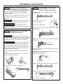
STEP 1 REMOVE PACKAGING
AND INSTALLATION PARTS
• Remove corner blocks and foam drawer stops.
• Remove all packing material, tape and protective
plastic coverings.
• Remove the toekick attached to the back of the unit.
• Remove the custom panel attached to the front of
the unit.
WARNING
Small objects are a choke hazard for
children. Remove and discard any parts not used.
AVERTISSEMENT
Les petits objets peuvent
étrangler les enfants. Il faut jeter toutes les pièces qui
ne sont pas utilisées.
STEP 2 REVERSING THE DOOR
(ZIFI240 model only)
WARNING
Follow all steps when reversing the
door swing. Failure to follow these instructions, leaving
off parts, or overtightening screws, can lead to the door
falling off and result in injury and property damage.
AVERTISSEMENT
Suivez toutes les étapes pour
inverser le sens d’ouverture de porte. L’omission de
suivre ces instructions, de ne pas utiliser toutes les
pièces, ou le serrage excessif des vis, peuvent causer
la chute de la porte et occasionner des blessures ou
des dommages à la propriété.
• Remove top hinge and discard. Hold the door in
place.
• Remove the black screw-hole cover from top left of
cabinet and insert in top right.
• Remove the top trim cover and discard.
STEP 2 REVERSING THE DOOR
(Cont.)
(ZIFI240 model only)
• Remove 4 screws to remove the top door trim (do
NOT discard).
• Remove the top hinge pin
(do NOT discard).
• Flip the door 180 degrees.
• Remove 3 screws to remove the bottom door trim (do
NOT discard)
• Remove 2 screws to remove the door stop and discard
door stop.
• Remove 1 screw to remove the bottom hinge pin and
discard hinge pin.
NOTE: Make sure the door is upside down so what
was the bottom is now the top.
• Insert the top hinge pin.
• Install top door trim onto the new top side of the door.
• Install the new top trim cover that snaps into place.
• Flip the door 180 degrees.
Installation Instructions

10 31-51544-10
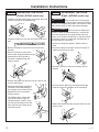
STEP 2 REVERSING THE DOOR
(Cont.)
(ZIFS240 model only)
WARNING
Follow all steps when reversing the
door swing. Failure to follow these instructions, leaving
off parts, or overtightening screws, can lead to the door
falling off and result in injury and property damage.
AVERTISSEMENT
Suivez toutes les étapes pour
inverser le sens d’ouverture de porte. L’omission de
suivre ces instructions, de ne pas utiliser toutes les
pièces, ou le serrage excessif des vis, peuvent causer
la chute de la porte et occasionner des blessures ou
des dommages à la propriété.
• Remove top hinge and discard. Hold the door in
place.
• Remove the black screw-hole cover from top left of
cabinet and insert in top right.
• Remove 2 screws tor remove the toekick (do not
discard).
• Remove bottom right hinge and discard the hinge.
Keep the screw for installation of the new hinge.
• Attache the bottom left hinge with the screw from the
previous step.
STEP 2 REVERSING THE DOOR
(Cont.)
(ZIFI240 model only)
• Install the new left bottom hinge pin and new door stop
that are enclosed in the hardware bag.
• Install the bottom trim onto the new bottom side of the
door.
• Remove 2 screws to remove the toe kick (do NOT
discard).
• Remove 4 screws to remove the
bottom right hinge (discard the hinge).
• Install bottom left hinge that is
enclosed in hardware bag with
existing screws.
• Remove the plastic cap from the top left corner of the
toe kick and discard.
• Attach the new plastic cap that is
enclosed in the hardware bag to
the top right corner of the toe kick.
• Reinstall toe kick to unit with 2
existing screws.
• To install the door, set the door
onto the left bottom hinge pin.
Holding the door in place, insert
the new top left hinge pin into the
door and secure the hinge to the
case with screws.
Installation Instructions

31-51544-10 11
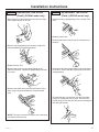
STEP 2 REVERSING THE DOOR
(Cont.)
(ZIFS240 model only)
• Move the plug on the toekick from the left to the right
and reattach toekick to the unit.
• Remove top plug/bushing from the door using a flat
head screwdriver. Discard the bushing.
• Rotate the door 180°.
• Remove the screw from the plug/bushing on the
bottom of the door. Discard the plug/bushing but keep
the screw.
• Remove the black screw post from the bottom of the
door using a flat head scewdriver. Keep the screw
post.
NOTE: The top will now be the bottom of the door and
the bottom is now the top.
STEP 2 REVERSING THE DOOR
(Cont.)
(ZIFS240 model only)
• Insert the new top plug/bushing in the new top of the
door.
• Rotate the door 180°.
• Re-insert the black screw post in the new bottom of
the door.
• Insert the new bottom plug/bushing in the new bottom
of the door. Secure with the screw removed from the
old plug/bushin.
• To install the door, set the door onto the left bottom
hinge pin. Holding the door in place, insert the new
top left hinge pin into the door and secure the hinge to
the case with screws.
Installation Instructions

12 31-51544-10
Installation Instructions
Spacer Panel
Backer Panel
Overlay Panel
STEP 3 INSTALL CUSTOM 3/4”
DOOR PANEL AND
HANDLE
(ZIFI240 and ZIBI240
models only)
3/4” Overlay Panel Dimensions
Model ZIFI240 and ZIBI240 require
a field-installed overlay door panel.
• The overlay panel must be
secured to a 1/4” thick backer
panel that slides into the trim. A
.10” thick spacer panel must be
placed between the overlay and
backer panel.
• A custom handle of your choice,
supplied by your cabinetmaker,
must be installed on this overlay panel. Countersink all
screws into the backer panel. Screws cannot protrude
from the backer panel.
IMPORTANT NOTE: Maximum total weight for custom
door panel is 25 pounds.
Assemble overlay panels with glue and screws.
• Center spacer panel on the backer panel, left to right and top
to bottom. Secure the panels with glue.
• Center the spacer/backer panel on the overlay panel.
Secure with glue and screws. Countersink all screws into
the backer panel.
STEP 3 INSTALL CUSTOM 3/4”
DOOR PANEL AND
HANDLE
(ZIFI240 and ZIBI240
models only)
Custom Panel Hinge Routing Dimensions
Use a 3/4” router bit to cut a notch into the back side of
the assembled panel 3/8” toward the front of the overlay
panel, 3/4” deep and 7/8” wide.
Install custom door panel and handle:
• Open door to 90°.
• Remove 5 screws holding trim; lift off trim.
Retain screws.
• A custom handle of your choice, supplied by your
cabinetmaker, must be installed onto the overlay panel
before the panels are slid into the trim. Countersink all
screws into the backer
panel. Screws cannot
protrude from the
backer panel.
1/4"
Backer
Panel
Door
.10 Inch
Spacer
Overlay
Panel
A
B
3/4” Overlay Panel Dimensions (in inches)
A (Width) B (Height)
1/4” Backer 23-3/16” 29-9/16”
0.10” Spacer 22-1/2” 29-1/16”
3/4” Overlay 23-5/8” 30”
3/8”
7/8”
3/4”
Back side
of custom
panel
3/4”
7/8”
3/8”
NOTE: Right-hand models
illustrated. Cut notches on the
opposite side for left-hand fresh
food door swing models
ZIFI240 and ZIFS240.
NOTE: Right-hand
models illustrated. Follow
the same instructions
on the opposite side for
left-hand fresh food door
swing models ZIFI240
and ZIFS240.
Handle
Custom
Door Panels
Screws Must
Be Countersunk
Into Panel

31-51544-10 13
STEP 3 INSTALL CUSTOM 3/4”
DOOR PANEL AND
HANDLE
(ZIFI240 and ZIBI240
models only)
• Slide overlay panel into the door trim.
• Reinstall the side trim using the trim screws removed
earlier.
• Place the brushed decorative cover over the side trim
to hide the screw heads. Ensure side trim is aligned top
to bottom and front to back. Snap into place.
STEP 4 LEVEL
• Use an adjustable
wrench to turn the
leveling legs and raise
or lower the product.
For built-in installation,
adjust the leveling legs
slightly below the bottom
of the countertop.
INSTALLATION TIP:
Measure floor to
underside of countertop
inside the opening. If
the room floor is higher
than the opening floor,
adjust the rear leveling legs approximately 1/8” less
than the opening height. Screw front legs all the way in
to shorten the height at the front. This will allow you to
slightly tip the unit into the opening. Once in the correct
position, the front legs can be adjusted to level the
product.
STEP 5 CONNECT WATER SUPPLY
(ZIBI240 and ZIBS240 models only)
WARNING
Connect to potable water supply
only.
AVERTISSEMENT
Raccordez l’appareil à une
alimentation d’eau potable seulement.
• Locate and bring the water line tubing to the rear of
the cabinet.
• Turn the water on to flush debris from the line. Run
about a quart of water through the tubing into a
bucket, then shut off the water.
Copper Tubing:
• Slip a 1/4” nut and ferrule over both ends of the
copper tubing. Insert the tube into the refrigerator
connection on the unit and tighten the nut.
• Turn on the water to check for leaks.
SmartConnect
™
Tubing:
• Insert the molded end of the tubing into the refrigerator
connection. Tighten the compression nut until it is just
hand tight.
• Tighten one additional turn with a wrench.
Overtightening can cause leaks!
• Turn on the water to check for leaks.
NOTE: Coil excess tubing length behind the unit.
Installation Instructions
Turn Right to Lower
Turn Left to Raise
NOTE:
For shipping
purposes, the
brushed decorative
cover will be
secured to
the front of
the unit.
Water line

14 31-51544-10
Installation Instructions
STEP 6 CONNECT POWER
• Connect power cord plug to a properly grounded
receptacle.
• Check to make sure power is on by opening the door
to see if interior light turns on.
• Bar Refrigerator with Icemaker – The interior fan runs
all the time except during defrost cycle when the door
is open.
• Fresh-Food Refrigerator – The interior fan runs all the
time except when the door is open.
See the Owner’s Manual for further explanation of the fan.
STEP 8 SET TEMPERATURE
CONTROLS
• The temperature controls are preset. Refer to the
Owner’s Manual for more information. Allow 12–24
hours for the temperature to stabilize.
NOTE: The Fresh-Food Refrigerator or Bar Refrigerator
with Icemaker operate very quietly. You may not notice
the unit running, and when first installed, the fans and
motor may not come on immediately – this is normal.
If the display is lit and the light is working, the unit is
operating.
STEP 7 SLIDE PRODUCT INTO
THE CUTOUT
NOTICE: Do not push against the door panel with your
knees. Do not push or lift the unit by the door handle.
Damage may occur.
• Open the door and gently push the unit back into the
opening with your hands against the sides. Be careful
not to entangle power cord.
• In a standard 24” opening, the front face of the
stainless steel door will be flush with adjacent
cabinetry. A custom panel door may protrude 1-3/4”
beyond the surrounding cabinets.
• Check again to be sure the unit is level.
• If the unit is installed under a countertop, adjust the
leveling legs until the unit is resting firmly against the
underside of the countertop.
• If alignment with adjacent cabinetry is an issue, use
a shim to secure the unit against the underside of the
countertop.

31-51544-10 15
Notes

NOTE: While performing installations described in this
book, safety glasses or goggles should be worn.
NOTE: Product improvement is a continuing endeavor
at Monogram. Therefore, materials, appearance and
specifications are subject to change without notice.
31-51544-10
02-19 GEA
Monogram.com
Printed in Serbia
-
 1
1
-
 2
2
-
 3
3
-
 4
4
-
 5
5
-
 6
6
-
 7
7
-
 8
8
-
 9
9
-
 10
10
-
 11
11
-
 12
12
-
 13
13
-
 14
14
-
 15
15
-
 16
16


GE ZIBI240HII Guide d'installation
- Catégorie
- Frigos
- Taper
- Guide d'installation
dans d''autres langues
- English: GE ZIBI240HII Installation guide