Powerfist 8937732 Le manuel du propriétaire
- Taper
- Le manuel du propriétaire

V4.0 8937732
Please read and understand all instructions before use. Retain this manual for
future reference.
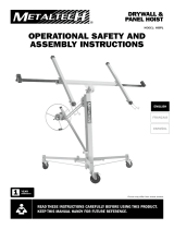
User Manual
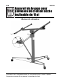
11 ft Drywall Hoist
with Tilting Action

8937732 11 ft Drywall Hoist with Tilting Action V4.0
2 For technical questions call 1-800-665-8685
SPECIFICATIONS
Capacity 150 lb
Max. Lifting Height 11 ft (132 in.)
Loading Height 4.5 ft (54 in.)
Caster Diameter 4 in.
Number of Casters 3 locking casters
Max. Panel Size 4 x 16 ft
Material Steel
INTRODUCTION
The drywall lift allows a single person to lift a drywall panel without assistance.
The lift cradle lowers to a convenient height for loading. Panels may then be
lifted to a flat roof with the lift cradle in the horizontal position. Tilting the lift
cradle allows lifting drywall to either a sloped roof or side wall.
SAFETY
WARNING! Read and understand all instructions before using this tool.
The operator must follow basic precautions to reduce the risk of
personal injury and/or damage to the equipment.
Keep this manual for safety warnings, precautions, operating or inspection
and maintenance instructions.
HAZARD DEFINITIONS
Please familiarize yourself with the hazard notices found in this manual. A
notice is an alert that there is a possibility of property damage, injury or
death if certain instructions are not followed.
11 ft Drywall Hoist
with Tilting Action

V4.0 11 ft Drywall Hoist with Tilting Action 8937732
Visit www.princessauto.com for more information 3
DANGER! This notice indicates an immediate and specific hazard that will
result in severe personal injury or death if the proper
precautions are not taken.
WARNING! This notice indicates a specific hazard or unsafe practice that
could result in severe personal injury or death if the proper
precautions are not taken.
CAUTION! This notice indicates a potentially hazardous situation that may
result in minor or moderate injury if proper practices are not
taken.
NOTICE! This notice indicates that a specific hazard or unsafe practice will
result in equipment or property damage, but not personal injury.
WORK AREA
1. Operate in a safe work environment. Keep your work area clean, well-lit
and free of distractions. Place lights so you are not working in a
shadow.
2. Keep anyone not wearing the appropriate safety equipment away from
the work area.
3. Store unused tools properly in a safe and dry location to prevent rust or
damage. Lock tools away and keep out of the reach of children.
PERSONAL SAFETY
WARNING! Wear personal protective equipment approved by the Canadian
Standards Association (CSA) or American National Standards Institute (ANSI).
PERSONAL PROTECTIVE EQUIPMENT
1. Always wear impact safety goggles that provide front and side protection
for the eyes. Eye protection equipment should comply with CSA Z94.3-07
or ANSI Z87.1 standards based on the type of work performed.
2. Wear the appropriate type of full-face shield in addition to safety
goggles, as the work can create chip, abrasive, or particulate matter.
3. Wear gloves that provide protection based on the work materials or to
reduce the effects of tool vibration.
4. Wear protective clothing designed for the work environment and tool.

8937732 11 ft Drywall Hoist with Tilting Action V4.0
4 For technical questions call 1-800-665-8685
5. Non-skid footwear is recommended to maintain footing and balance in
the work environment.
6. Wear steel toe footwear or steel toe caps to prevent a foot injury from
falling objects.
7. Wear the appropriate rated dust mask or respirator.
PERSONAL PRECAUTIONS
Control the tool, personal movement and the work environment to avoid
personal injury or damage to tool.
1. Do not operate any tool when tired or under the influence of drugs,
alcohol or medications.
2. Avoid wearing clothes or jewelry that can become entangled with the
moving parts of a tool. Keep long hair covered or bound.
3. Do not overreach when operating a tool. Proper footing and balance
enable better control in unexpected situations.
SPECIFIC SAFETY PRECAUTIONS
WARNING! DO NOT let comfort or familiarity with product (gained from
repeated use) replace strict adherence to the tool safety rules. If you use
this tool unsafely or incorrectly, you can suffer serious personal injury.
1. Use the correct tool for the job. This tool was designed for a specific
function. Do not modify or alter this tool or use it for an unintended
purpose.
2. Do not use the tool if any parts are damaged, broken, or misplaced.
Repair or replace the parts.
3. Always inspect the drywall lift carefully before each use, paying special
attention to the condition of the cable.
4. Always allow the lift to reach working room temperature before use.
Moving a cold unit into a warm room can cause condensation that will
affect the operation of the winch brake.
5. Always make sure the brake drum is clean and dry before operating.
6. Never use the lift if either crossbeam support is not secured by its
locking spring tab.

V4.0 11 ft Drywall Hoist with Tilting Action 8937732
Visit www.princessauto.com for more information 5
7. Always keep the work area free of obstructions.
8. Always wear a hard hat when using the lift.
9. Always watch for overhead obstructions when lifting a drywall panel.
10. Never use the lift for any other purpose other than lifting a drywall
panel.
11. Never lift more than one sheet of drywall at a time, and never exceed
the maximum rated capacity of this lift.
12. Do not exceed the tool’s weight or panel size capacity. The tool may fail
and injury you.
13. Large drywall panels are heavy. Use proper lifting methods when
loading the drywall onto the hoist to avoid a back injury.
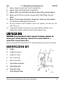
UNPACKING
WARNING! Do not operate the tool if any part is missing. Replace the
missing part before operating. Failure to do so could result in a
malfunction and personal injury.
Remove the parts and accessories from the packaging and inspect for damage.
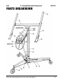
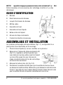
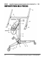
IDENTIFICATION KEY
A Cradle
B Cradle Crossarms
C Cradle Tilt Latch
D Frame Housing
E Winch Assembly
F Tripod Base Assembly
G Tripod Backstop
H Slide Yoke Ring
I Panel Support Hook
Fig. 1

8937732 11 ft Drywall Hoist with Tilting Action V4.0
6 For technical questions call 1-800-665-8685
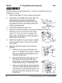
ASSEMBLY
Dashed numbers in parenthesis (Fig. 1-1) refer to a specific point in an
illustration or image.
1. Set the tripod base (F) on its casters on the floor.
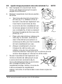
2. Press down on the slide yoke ring (G) (Fig. 2-1),
and hold it down while you swing the two
forward tripod legs to the sides until the yoke
ring snaps into place in the locking hole on the
bottom of the slide tube.
3. Lower the backstop (G) (Fig. 2-2).
4. Position the frame assembly so the winch assembly is above the
stationary center leg, then lower the frame
about 1 in. (2.5 cm), until it is seated in the
base’s tube. Verify that the frame assembly is
pushed all the way down.
5. Attach the handle to the winch wheel. Tighten
the nut, and then back it off until the handle
turns freely.
6. Move the winch assembly into its working
position.
a. Hold the winch wheel and brake arm
(Fig. 3-1). Release the brake by rotating
the winch wheel forward slightly while
lifting the brake arm.
b. Raise the brake arm all the way up, and
then grasp the winch post with your
fingers (Fig. 4) while firmly gripping the
brake handle with your thumb (Fig. 4-1).
c. Place your right hand on top of the frame
(Fig. 5). Continue gripping the brake arm
as needed to prevent cable backlash, and
then pull the winch assembly all the way
toward you.
Fig. 2
Fig. 3
Fig. 4
Fig. 5

V4.0 11 ft Drywall Hoist with Tilting Action 8937732
Visit www.princessauto.com for more information 7
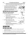
d. Extend the winch fully away from the frame housing, and then release
the brake arm and swing the retaining hook away so that it no longer
secures the telescoping sections inside the frame housing.
7. Press the winch assembly slightly back toward
the frame until the slide bar lock (Fig. 6)
automatically rotates clockwise to engage and
keep the winch fully extended. Verify that the
slide bar lock is fully engaged, that is, that it is
rotated clockwise as far as possible.
IMPORTANT! Never tighten the nut on the slide bar
lock, as this will make it impossible to fold the
drywall lift for transport and storage.
8. Attach the cradle to the frame.
a. Insert the cradle post into the opening on the
top of the frame.
b. Secure the cradle to the frame by
snapping the tilt latch (Fig. 7-1)
upward so that it hooks over the stud
(Fig. 7-2) on the cradle.
9. Attach the crossarms to the cradle.
a. Slide the tapered plates on the
crossarms into the tapered sockets on
the cradle (Fig. 8).
b. Press each crossarm forward into the
socket until the spring tab (Fig. 9-1) on the bottom of the
crossarm snaps into place.
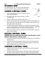
OPERATION
BEFORE EACH USE
1. Carefully inspect the drywall lift for wear or damage, paying special
attention to the cable.
2. Make sure the drywall lift is at working room temperature before operating.
3. Make sure the winch brake drum is clean and dry before operating.
Fig. 6
Fig.
7
Fig. 8
Fig. 9

8937732 11 ft Drywall Hoist with Tilting Action V4.0
8 For technical questions call 1-800-665-8685
TRIPOD BASE SET-UP
1. Swing the two tripod legs on either side outwards. Press the yoke ring
(H) towards the tube until it snaps into position to secure the legs.
2. Lower the backstop (G) to prevent the base from rolling while loading
the hoist.
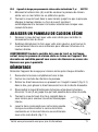
PANEL SUPPORT HOOKS
Open the panel support hook (I) on each crossarm to support the drywall
panel during loading or when the cradle is being tilted.
CAUTION! Always fully retract the panel support hooks before
transporting or storing the drywall lift.
SLIDE BAR LOCK
WARNING! The slide bar lock must be fully engaged whenever the winch
assembly is extended, in order to prevent a crushing injury.
Fully extend the winch assembly and then press it back slightly toward the
frame to automatically engage the lock (Fig. 6).
Turn the lock counterclockwise while lifting on the slide bar to fold the winch
assembly against the frame when disassembling the drywall lift for transport
or storage.
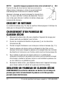
TILT LATCH
The tilt latch allows the cradle to tilt when loading a drywall panel or aligning
the panel with a side wall or sloping ceiling. Pivot the tilt latch (Fig. 7-2) up
to engage the cradle’s stud before lifting. This locks the cradle onto the
frame. The cradle can still tilt by 10º from side-to-side.
Flip the tilt latch back down when storing the hoist.
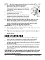
WINCH AND BRAKE
Grasp the post for leverage when cranking the winch in either direction.
Crank the winch’s wheel upward to coil the cable and raise the cradle. The
spring-loaded brake automatically holds the cradle at the desired height.
Lower the cradle by slowly lifting the brake arm (Fig. 4-1) to control the rate
of descent. Crank downward to uncoil cable to match the cradle’s descent.

V4.0 11 ft Drywall Hoist with Tilting Action 8937732
Visit www.princessauto.com for more information 9
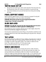
RETAINING HOOK
The retaining hook (Fig. 10) secures the telescoping
sections inside the frame for transport and storage.
LOADING A DRYWALL PANEL
1. Lower the backstop (G) to prevent the drywall lift
from rolling backward.
2. Swing open the panel support hooks (I) on both
crossarms (B).
3. Flip the tilt latch down to tilt the cradle (Fig. 7-1).
4. Hold the drywall panel with its face paper toward the tilted cradle, and
then load the panel by setting it onto the support hooks and leaning it
back against the crossarms (B).
5. If you are installing the drywall panel on a flat ceiling, then tilt the cradle
back to its level position, and then lock the tilt latch. Leave the cradle tilted
if you are installing the panel on a side wall or sloped ceiling.
6. Raise the backstop, and then carefully roll the drywall lift to where the
panel will be installed.
RAISING A DRYWALL PANEL
WARNING! Watch for overhead obstacles when raising the panel, to avoid
tipping it and/or the hoist, causing an injury.
1. Lower the backstop (G) before raising the drywall panel to a side wall or
sloped ceiling.
2. Crank the winch wheel clockwise until the panel reaches the desired
height. The spring loaded brake automatically keeps the cradle at the
selected height when you stop cranking.
LOWERING A DRYWALL PANEL
1. Grasp the winch wheel with your right hand to control the backward
movement of the winch.
2. Carefully release the brake with your left hand, and then slowly rotate
the wheel counterclockwise to lower the cradle to the desired height.
Fig. 10

8937732 11 ft Drywall Hoist with Tilting Action V4.0
10 For technical questions call 1-800-665-8685
WARNING! Maintain control of the winch wheel at all times, especially if
there is a drywall panel loaded. An uncontrolled descent may cause an
injury to yourself or a bystander.
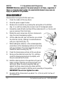
DISASSEMBLY
Disassemble the drywall lift after each use.
1. Crank the cradle all the way down.
2. Close the panel support hooks.
3. Remove the crossarms by pressing the spring tab on the bottom
(Fig. 9-1), and then sliding the crossarm out of the tapered socket.
4. Unlock the cradle tilt latch and then lift the cradle about 3 in. (7.5 cm) until
you can remove it from the frame.
5. Rotate the winch wheel one full turn clockwise to
raise the inner telescoping section.
6. Lift the slide bar with your left hand as you unlock
the slide bar lock by rotating it counterclockwise
with your right hand (Fig. 11).
7. While holding the slide bar in the unlocked position,
press down on the telescoping sections in the frame
with your left hand. The winch assembly will move
toward the frame housing (Fig. 12).
8. Crank the telescoping sections all the way down.
9. Swing up the retaining hook (Fig. 10), and then
crank the telescoping sections up slightly until
they are secured by the hook.
10. Hold the retaining hook in this position with your left
hand, and then rotate the winch forward with your
right hand. When the winch assembly folds up
against the frame, keep turning the wheel until the
cable is just tight enough to hold the winch assembly in this position.
IMPORTANT! Do not over-tighten the cable.
11. Carefully lift the frame/winch up about 1 in. (2.5 cm) until it is free of
the tripod base.
Fig. 11
Fig. 12

V4.0 11 ft Drywall Hoist with Tilting Action 8937732
Visit www.princessauto.com for more information 11
12. Fold the base by pressing down on the slide yoke ring (H), then pivot
the legs in until they lock in the closed position.
CARE & MAINTENANCE
WARNING! Only qualified service personnel should repair the tool. An
improperly repaired tool may present a hazard to the user and/or others.
1. Maintain the tool with care. A tool in good condition is efficient, easier
to control and will have fewer problems.
2. Inspect the tool components periodically. Repair or replace damaged or
worn components. Only use identical replacement parts when servicing.
3. Maintain the tool’s labels and name plates. These carry important
information. If unreadable or missing, contact Princess Auto Ltd. for
replacements.
WARNING! Only qualified service personnel should repair the tool. An
improperly repaired tool may present a hazard to the user and/or others.
CLEANING
Clean the drywall lift thoroughly a damp cloth after each use.
LUBRICATION
Lubricate moving parts (pulleys, hinges, bearings, etc.) with light oil or
grease
STORAGE
The drywall lift should not be stored outside; it may corrode. Keep the
drywall lift in a covered, dry place. If desired, you may disassemble the
drywall lift as described in Disassembly.
REMOVAL FROM STORAGE
1. Inspect the drywall lift to ensure that all parts are tight and in working
order and that the drywall lift is clean and free of rust or corrosion.
2. Assemble the drywall lift, if needed.
3. Perform all of the Before Each Use procedures, above.

8937732 11 ft Drywall Hoist with Tilting Action V4.0
12 For technical questions call 1-800-665-8685
DISPOSAL
Recycle a tool damaged beyond repair at the appropriate facility.
TROUBLESHOOTING
Visit a Princess Auto Ltd. location for a solution if the tool does not function
properly or parts are missing. If unable to do so, have a qualified technician
service the tool.

V4.0 11 ft Drywall Hoist with Tilting Action 8937732
Visit www.princessauto.com for more information 13
PARTS BREAKDOWN

8937732 11 ft Drywall Hoist with Tilting Action V4.0
14 For technical questions call 1-800-665-8685
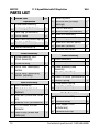
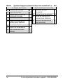
PARTS LIST
# DESCRIPTION QTY
Tripod Base
1
Tripod Base Assembly
1
2 Center Leg (w/fasteners) 1
3
Outer Leg (w/fasteners)
2
4
10 cm Caster
3
5
Slide Yoke Ring Tension Spring
1
6
Tie Arm (w/fasteners)
2
7 Rubber Backstop Tip 2
Frame Assembly
10
Frame Assembly (incl.
Winch Assembly)
1
11
Frame Housing
1
12
10 cm Inner Telescoping
Section
1
13
10 cm Outer Telescoping
Section (w/pulley)
1
Winch Assembly
20
Winch Assembly
1
21 Winch Hub (w/pin and
fastener)
1
22
Slide Bar (w/axle and cotter
pin)
1
23
Slide Bar Lock (w/fasteners)
1
24
411 cm Cable, 3.5 mm
diameter
1
25
Cable Pulley (w/axle and
cotter pin)
1
26 Retaining Hook 1
27
Winch Wheel (w/flange
bearings)
1
28
2.22 cm Bushing
1
29 M12x125 Bolt (w/fasteners) 1
30
Brake Arm Assembly
1
31
Brake Lining (w/fasteners)
1
32
Brake Arm Tension Spring
1
33
Brake Hub (w/bolts)
1
34
Winch Wheel Handle
1
Cradle Assembly
40
Cradle Assembly
1
41
Cradle Body
1
44
Cradle Mounting Lead
Assembly
1
45
Mounting Head Body
1
46
Cradle Tilt Latch (w/fasteners)
1
47
Tension Spring
1
48
Compression Spring 2
49
Hinge Pin (w/bolts) 1
Cradle Crossarms
60
Crossarm Assembly
2
61
Crossarm Body 2
62
Panel Support Lock
(w/fasteners)
2
63
Crossarm End Cap
2

V4.0 11 ft Drywall Hoist with Tilting Action 8937732
Visit www.princessauto.com for more information 15

8937732 11 ft Drywall Hoist with Tilting Action V4.0
16 For technical questions call 1-800-665-8685

V4,0 8937732
Vous devez lire et comprendre toutes les instructions avant d'utiliser l'appareil.
Conservez ce manuel afin de pouvoir le consulter plus tard.
Manuel d'utilisateur
Appareil de levage pour
panneaux de cloison sèche
inclinable de 11 pi

8937732 Appareil de levage pour panneaux de cloison sèche inclinable de 11 pi V4,0
2 En cas de questions techniques, appelez le 1-800-665-8685
SPÉCIFICATIONS
Capacité 150 lb
Hauteur de levage max. 11 pi (132 po)
Loading Height 4,5 pi (54 po)
Diamètre de roulette 4 po
Nombre de roulettes 3 roulettes à blocage
Taille de panneau max.
4 x 16 pi
Matériau Acier
INTRODUCTION
L’appareil de levage pour cloison sèche permet à une personne seule de
soulever un panneau de cloison sèche sans aucune aide. Le berceau de
levage s’abaisse à une hauteur pratique pour le chargement. Lorsque le
berceau de levage est en position horizontale, le panneau peut alors être
soulevé pour être posé sur un plafond plat. En inclinant le berceau de levage,
la cloison sèche est soulevée et peut être posée sur un plafond en pente ou
un mur latéral.
SÉCURITÉ
AVERTISSEMENT ! Veuillez lire et comprendre toutes les instructions
avant d'utiliser cet outil. L'utilisateur doit respecter les précautions de
base lorsqu'il utilise cet outil afin de réduire le risque de blessure ou de
dommage à l'équipement.
Conservez ce manuel qui contient les avertissements de sécurité, les
précautions, les instructions de fonctionnement ou d'inspection et d'entretien.
Appareil de levage pour
panneaux de cloison sèche
inclinable de 11 pi

V4,0 Appareil de levage pour panneaux de cloison sèche inclinable de 11 pi 8937732
Visitez www.princessauto.com pour plus d'informations 3
DÉFINITIONS DE DANGER
Veuillez-vous familiariser avec les avis de danger qui sont présentés dans ce
manuel. Un avis est une alerte indiquant qu'il existe un risque de dommage à la
propriété, de blessure ou de décès si on ne respecte pas certaines instructions.
DANGER ! Cet avis indique un risque immédiat et particulier qui
entraînera des blessures corporelles graves ou même la
mort si on omet de prendre les précautions nécessaires.
AVERTISSEMENT ! Cet avis indique un risque particulier ou une pratique non
sécuritaire qui pourrait entraîner des blessures corporelles
graves ou même la mort si on omet de prendre les
précautions nécessaires.
ATTENTION ! Cet avis indique une situation possiblement dangereuse qui
peut entraîner des blessures mineures ou modérées si on ne
procède pas de la façon recommandée.
AVIS ! Cet avis indique un risque particulier ou une pratique non
sécuritaire qui entraînera des dommages au niveau de
l'équipement ou des biens, mais non des blessures corporelles.
AIRE DE TRAVAIL
1. Travaillez dans un environnement de travail sécuritaire. Gardez votre
aire de travail propre, bien éclairée et exempte de toute distraction.
Placez les lampes de façon à ne pas travailler dans l’ombre.
2. Assurez-vous que les personnes qui ne portent pas l'équipement de
sécurité approprié ne se trouvent pas à proximité de l'aire de travail.
3. Rangez les outils correctement dans un lieu sécurisé et sec. Gardez les
outils hors de la portée des enfants.
SÉCURITÉ PERSONNELLE
AVERTISSEMENT ! Portez de l'équipement de protection personnelle
homologué par l'Association canadienne de normalisation (CSA) ou
l'American National Standards Institute (ANSI).
ÉQUIPEMENT DE PROTECTION PERSONNELLE
1. Portez toujours des lunettes antiprojections qui offrent une protection
frontale et latérale pour les yeux. L'équipement de protection des yeux

8937732 Appareil de levage pour panneaux de cloison sèche inclinable de 11 pi V4,0
4 En cas de questions techniques, appelez le 1-800-665-8685
devrait être conforme à la norme CSA Z94.3-07 ou ANSI Z87.1 fonction
du type de travail effectué.
2. Portez un écran facial panoramique de type approprié avec les lunettes
de sécurité puisque cette tâche peut créer des copeaux, des matières
abrasives ou des particules.
3. Portez des gants qui protègent en fonction des matériaux de travail et
pour réduire les effets des vibrations de l'outil.
4. Portez des vêtements de protection conçus pour l'environnement de
travail et pour l'outil.
5. Les chaussures antidérapantes sont recommandées pour maintenir la
stabilité et l'équilibre au sein de l'environnement de travail.
6. Portez des chaussures à embout d'acier ou à coquilles d'acier pour
éviter les blessures aux pieds dues à la chute d'objets.
7. Portez un masque antipoussières ou un appareil respiratoire
nominal approprié.
PRÉCAUTIONS PERSONNELLES
Gardez le contrôle de l'outil, de vos mouvements et de l'environnement de
travail pour éviter les blessures ou le bris de l'outil.
1. N'utilisez pas l'outil si vous êtes fatigué ou sous l'effet de drogues,
d'alcool ou de médicaments.
2. Évitez de porter des vêtements ou des bijoux pouvant se prendre dans les
pièces mobiles d'un outil. Gardez les cheveux longs recouverts ou attachés.
3. N'utilisez pas l'outil si vous devez étirer les bras pour vous en servir.
Une stabilité et un équilibre appropriés sont nécessaires afin d'avoir un
meilleur contrôle en cas de situations inattendues.
CONSIGNES DE SÉCURITÉ SPÉCIFIQUES
AVERTISSEMENT! Ne permettez PAS au confort ou à votre familiarisation
avec l'outil (obtenus après un emploi répété) de se substituer à une
adhésion stricte aux règles de sécurité de l'outil. Si vous utilisez cet
outil de façon dangereuse ou incorrecte, vous pouvez subir des blessures
corporelles graves.
1. Utilisez le bon outil pour la tâche à effectuer. Cet outil a été conçu pour
La page est en cours de chargement...
La page est en cours de chargement...
La page est en cours de chargement...
La page est en cours de chargement...
La page est en cours de chargement...
La page est en cours de chargement...
La page est en cours de chargement...
La page est en cours de chargement...
La page est en cours de chargement...
La page est en cours de chargement...
La page est en cours de chargement...
La page est en cours de chargement...
-
 1
1
-
 2
2
-
 3
3
-
 4
4
-
 5
5
-
 6
6
-
 7
7
-
 8
8
-
 9
9
-
 10
10
-
 11
11
-
 12
12
-
 13
13
-
 14
14
-
 15
15
-
 16
16
-
 17
17
-
 18
18
-
 19
19
-
 20
20
-
 21
21
-
 22
22
-
 23
23
-
 24
24
-
 25
25
-
 26
26
-
 27
27
-
 28
28
-
 29
29
-
 30
30
-
 31
31
-
 32
32


Powerfist 8937732 Le manuel du propriétaire
- Taper
- Le manuel du propriétaire
dans d''autres langues
- English: Powerfist 8937732 Owner's manual
Documents connexes
Autres documents
-
 MetalTech I-IDPL Le manuel du propriétaire
-
King Canada KDL-11 Manuel utilisateur
-
Power Fist 8554099 Le manuel du propriétaire
-
-
-
-
-
