Scheppach mt 180t Assembly Instructions Manual
- Taper
- Assembly Instructions Manual

Art.Nr.
4907102900
4907102851 | 09/2014
DE
Universal Sägetisch - Aufbauanleitung 4
GB
Universal Saw Stand – Assembly Instructions 5
FR
Table de sciage universelle - Instructions de montage 6
mt 180 t


4
HERSTELLER:
scheppach
Fabrikation von Holzbearbeitungsmaschinen GmbH
Günzburger Straße 69
D-89335 Ichenhausen
VEREHRTER KUNDE,
Wir wünschen Ihnen viel Freude und Erfolg beim Arbei-
ten mit Ihrem neuen Universal-Sägetisch.
ALLGEMEINE HINWEISE
• Überprüfen Sie nach dem Auspacken alle Teile auf
even tu elle Transportschäden. Wenden Sie sich bei
Beanstandungen an den Händler, bei dem Sie den
Universal-Sägetisch erworben haben. Spätere Rekla-
mationen werden nicht anerkannt.
ACHTUNG
Gerät und Verpackungsmaterialien sind kein Kinder-
spielzeug! Kinder dürfen nicht mit Kunststoffbeuteln,
Folien und Kleinteilen spielen!
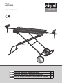
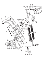
Lieferumfang, Fig. 1
1. Grundrahmen
2. Fußstütze
3. Handgriff
4. Räder mit Kugellager 2x
6. Laufrollen 2x
7. Radbolzen 2x
8. Handgriff (Tisch)
Flachkopfschraube (M6x35) 2x
Sicherungsmuttern 2x
Flachkopfschraube (M6x12) 4x
Federscheiben 4x
Beilagscheibe 4x
Mutter M8 4x
Sterngriffschraube 4x
Sterngriff 2x
Schlossschraube (M8x45) 4x
Bogenscheibe 4x
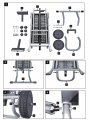
Montage
Fig. 2
Setzen Sie die beiden Endkappen auf das Verlänge-
rungsrohr und stecken Sie dieses in das Grundgestell,
Befestigung mit 2 Flachkopfschrauben (M6x12) und 2
Bogenscheiben.
Fig. 3
Handgriff (3) in Grundrahmen einführen, mit 2 Flach-
kopfschrauben (M6x12) und 2 Bogenscheiben befesti-
gen.
Fig. 4
Radbolzen (7) mit Kugellager und Rad (4) durch die
Radbuchse im Rahmen einführen und mit der Siche-
rungsmutter (8) anziehen. Darauf achten dass sich das
Rad noch bewegen lässt.
Fig. 5 - 5.1
Sichern Sie die Kreuzschlitzschraube (1) mit dem Stern-
griff (c).
Dies wiederholen Sie ebenso auf der anderen Seite.
Gerät auf Fuß und Räder stellen, Sperrhebel (a) zie-
hen und Arbeitsäche (b) nach oben ziehen bis diese
einrastet.
Achtung! Quetschgefahr
Beidseitig mit den Sterngriffen (c) sichern.
Fig. 6
Verlängerungsrohr (5) in das Vierkantrohr einschieben
bis die Führungsbuchse anliegt und mit der Sterngriff-
schraube (e) sichern.
Fig. 7
Laufrollen (6) in Vierkantrohr der Verlängerung einste-
cken und mit Sterngriffschrauben (e) sichern.
Fig. 8 / 8.1
Universal-Sägetisch komplett montiert in
Stellung 1 (Arbeitshöhe = 82 cm)
Stellung 2 (Arbeitshöhe = 68,5 cm)
Stellung 3 (Transportstellung)
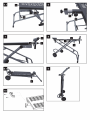
Fig. 9
Zum Verstauen stellen Sie den Universal-Sägetisch auf.
Fig. 10
Montieren Sie den Handgriff am Tisch wie auf dem Bild
zu sehen mit 2 Flachkopfschrauben M6x35.

5
MANUFACTURER:
scheppach
Fabrikation von Holzbearbeitungsmaschinen GmbH
Günzburger Straße 69
D-89335 Ichenhausen
DEAR CUSTOMER,
We wish you success and hope you will enjoy working
with your new universal saw stand.
GENERAL ADVICE
• After opening please check all parts for possible da-
mage during shipping. In case of a grievance, ple-
ase contact the retailer from whom you purchased
the universal saw stand. Later complaints will not be
accepted.
ATTENTION
The device and the packaging materials are not toys!
Children must not play with plastic bags, foils and
small pieces!
Items delivered, Fig. 1
1. Base frame
2. Support pole
3. Handgrip
4. Wheels with ball bearing 2x
6. Guide rollers 2x
7. Wheel bolts 2x
8. Handgrip (table)
Pan head screw (M6x35) 2x
Locking nuts 2x
Pan head screw (M6x12) 4x
Arc washers 4x
Star knob screw 4x
Star knob 2x
Carriage Bolt (M8x45) 4x
M8 nut 4x
Spring washers 4x
Flat washers 4x
Assembly
Fig. 2
Insert the two end caps into the support pole and then
insert the support pole (2) with end caps into the base
frame, securing it with 2 pan head screws (M6x12) and
2 arc washers.
Fig. 3
Insert the handgrip (3) into the base frame, securing it
with 2 pan head screws (M6x12) and 2 arc washers.
Fig. 4
Insert the wheel bolts (7) with ball bearings and wheel
(4) through the wheel socket on the frame and tighten
with the locking nuts (8). Take care that the wheels are
still able to move.
Fig. 5 - 5.1
Secure the Phillips-screw (1) with the star knob (c).
Repeat this process also on the other side.
Stand the device on the support pole and wheels, pull
the ratchet lever (a) and pull the worktop (b) up until it
latches.
Warning! Crushing hazard
Secure with star knobs (c) on both sides.
Fig. 6
Slide the extension tube (5) into the square tube as
far as the guide sleeve allows and secure with the star
knob screws (e).
Fig. 7
Insert the guide rollers (6) into the square tube of the
extension and secure with the star knob screws (f).
Fig. 8 / 8.1
The universal saw stand assembly is complete in
Position 1 (Work height = 82 cm)
Position 2 (Work height = 68,5 cm)
Position 3 (transport position)
Fig. 9
For storage, position the universal saw bench upwards.
Fig. 10
Assemble the handle with two pan head screws (M6x35)
on the table as you can see on the picture.

6
FABRICANT:
scheppach
Fabrikation von Holzbearbeitungsmaschinen GmbH
Günzburger Straße 69
D-89335 Ichenhausen
CHER CLIENT,
Nous vous souhaitons beaucoup de satisfaction et de
réussite en travaillant avec votre nouvelle table de scia-
ge universelle.
REMARQUES GENERALES
• Lors du déballage, vériez toutes les pièces pour
constater d‘éventuels dommages occasionnés lors
du transport. En cas de réclamations, adressez-vous
au revendeur à qui vous avez acheté la table de scia-
ge universelle. Nous ne pouvons tenir compte des
réclamations ultérieures.
ATTENTION
L‘appareil et les matériaux d‘emballage ne sont pas
des jouets pour enfants ! Les enfants ne doivent pas
jouer avec les sacs en plastique, les lms plastique et
les petites pièces !
Contenu de la livraison, Fig. 1
1. Châssis de base
2. Pied-support
3. Poignée
4. Roues équipées de roulements 2x
6. Servantes 2x
7. Axes de roues 2x
8. Poignée (table)
Vis à tête conique (M6x35) 2x
Ecrous autoserrants 2x
Vis à tête conique (M6x12) 4x
Rondelles ressort 4x
Rondelles 4x
Ecrous M8 4x
Poignées moletées 4x
Poignées moletées 2x
Boulons (M8x45) 4x
Rondelle courbe 4x
Montage
Fig. 2
Insérez les deux bouchons en place sur les extrémi-
tés du tube et emmanchez-le sur le châssis de base,
xez-le avec 2 vis à tête conique (M6x12) et 2 rondel-
les courbes.
Fig. 3
Insérez la poignée (3) dans le châssis de base. Fixez-la
avec 2 vis à tête conique (M6x12) et 2 rondelles cour-
bes.
Fig. 4
Insérez les axes de roues (7) avec les roues (4) au tra-
vers du tube du châssis et serrez-les avec les écrous
autoserrants (8). Veillez à ce que les roues puissent
continuer à tourner.
Fig. 5 - 5.1
Fixez la vis cruciforme (1) avec la poignée-moletée (c).
Répétez ce processus de l‘autre côté.
Placez l‘appareil sur son pied et ses roues, tirez sur le
levier de blocage (a) et tirez la surface de travail (b) vers
le haut jusqu‘à ce qu‘elle s‘enclenche.
Attention ! Risque de pincement !
Sécurisez des deux côtés avec les poignées moletées
(c).
Fig. 6
Insérez le tube du support (5) dans le tube carré jusqu‘à
ce que le manchon soit bien positionné et bloquez-le
avec la poignée moletée (e).
Fig. 7
Insérez les servantes (6) dans le tube -support et xez-
le en serrant la poignée moletée (e).
Fig. 8 / 8.1
La table de sciage universelle est complètement as-
semblée en
Position 1 (hauteur de travail = 82 cm)
Position 2 (hauteur de travail = 68,5 cm)
Position 3 (Position de transport)
Fig. 9
Repliez et placez la table de sciage universelle à la ver-
ticale pour la stocker.
Fig. 10
Fixez la poignée à la table comme montré en g.10 avec
2 vis à tête conique (M6x35).


scheppach Fabrikation von Holzbearbeitungsmaschinen GmbH | Günzburger Str. 69 |
D-89335 Ichenhausen | www.scheppach.com
-
 1
1
-
 2
2
-
 3
3
-
 4
4
-
 5
5
-
 6
6
-
 7
7
-
 8
8


Scheppach mt 180t Assembly Instructions Manual
- Taper
- Assembly Instructions Manual
dans d''autres langues
- English: Scheppach mt 180t
- Deutsch: Scheppach mt 180t
Documents connexes
-
Scheppach 5901501958 Manuel utilisateur
-
-
-
-
-
-
-
-
Scheppach Deco-flex Manuel utilisateur