
INTRODUCTION
Congratulations on your purchase of a Champion Power Equipment winch.
CPE designs and builds winches to strict specifications and with proper use
and maintenance should bring you years of satisfying service.
WARNING - Read, study and follow all instructions before operating this
device. Failure to heed these instructions may result in personal injury and/or
property damage.
Your winch can develop tremendous pulling forces and if used unsafely or
improperly could result in property damage, serious injury or death.
Throughout this manual you will find the following symbols for caution, warning
and danger. Pay particular attention to the notes preceded by these symbols as
they are written for your safety. Ultimately, safe operation of this device rests
with you, the operator.
Indicates a potentially hazardous situation which, if not avoided, may
result in minor or moderate injury. This notation is also used to alert
against unsafe practices.
Indicates a potentially hazardous situation which, if not avoided
could result in death or serious injury.
CAUTION

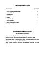
INCLUDED WITH YOUR WINCH
DESCRIPTION QUANTITY
1. Winch Assembly with Wire Rope 1
2. Cap Bolt M8 x 30 2
3. Lock Washers 2
4. Flat Washers 2
5. M8 Nuts 2
6. Snatch Block/Pulley 1
7. Clevis Hook w/Pin 1
8. Power Cord/Switch Assembly 1
9. Hand Saver Hook 1
WINCH ACCESSORIES YOU WILL NEED
NOT INCLUDED WITH YOUR WINCH
Gloves – For handling the wire rope and hook strap.
Clevis/D-shackle – For connecting your snatch block and anchor strap.
Anchor Strap/Chain – Tree saver anchor straps are made of high quality nylon
with high tensile strengths from 5,000 to 10,000lbs.
Heavy Blanket – place on the cable to absorb energy should the wire rope
break.

Winch ASSEMBLY AND MOUNTING
1. Your CPE 2,000 lb winch is designed with a bolt pattern that is standard
in this class of winch. Many winch mounting kits are available that utilize
this bolt pattern for the most popular ATV’s and mounting channels. If
you cannot find a kit locally, contact CPE and we will provide you with the
name of a dealer near you.
2. Regardless of the mounting kit you use, ensure that your CPE winch is
mounted on a flat surface so that the three major sections (motor, drum
and gear housing) are properly aligned. Proper alignment of the winch
will allow even distribution of the full rated load.
3. Utilize the M8 x 30 mounting bolts, washers and nuts included.
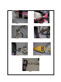
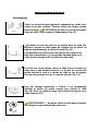
4. Connect the battery (5’ 9”) and motor (4’ 1”) leads. Connect the red
(Positive+) to the in-facing terminal (marked +) on the motor and the black
(Negative-) to the out-facing terminal (marked -) on the motor. Then
connect the red (Positive+) lead from the power switch to the positive (+)
terminal of the vehicles 12 volt battery. Connect the black (Negative -)
lead from the power switch to the negative (-) terminal of the battery.
(Fig.1 & Fig. 2) CAUTION – Batteries contain gases which are
flammable and explosive. Wear eye protection during installation and
remove all jewelry. Do not lean over battery while making connections.
5. Assemble the Clevis Hook to the cable. Pull and turn the clutch knob to
the “Off” position (Free-spooling). Pull out some cable from the drum.
Take off the pin from the Clevis Hook, connect the Clevis Hook to the
cable and mount the pin back to the Clevis Hook (Fig. 3 & Fig. 4)

6. Always use the Hand Saver when free-spooling and re-spooling the wire
rope. (Fig. 7) Using the Hand Saver will keeps your hands and fingers
away from the rotating drum.
7. Check for proper drum rotation. Pull and turn the clutch knob to the “off”
position (Free-spooling). Pull out some cable from the drum, then turn
the clutch knob to the “In” position to engage the gears. Press the cable
out button on the power switch. If the drum is turning and releasing more
cable then your connections are accurate. If the drum is turning and
collecting more cable then reverse the leads on the motor. Repeat and
check rotation.

Fig. 1 Fig. 2
Fig. 3 Fig. 4
Fig. 5 Fig. 6
Fig 7

SAFETY PRECAUTIONS
WARNING
WARNING – DO NOT EXCEED RATED CAPACITY.
WARNING – Intermittent use only.
WARNING - Do not use winch in lifting or moving or persons.
WARNING - A minimum of five wraps of cable around the drum barrel is
necessary for pulling and holding the rated load. The cable clamp is not
designed to hold the load without 5 wraps of cable around the barrel.
WARNING - Keep yourself and others a safe distance to the side of the
cable when under tension.
WARNING – The wire rope may break before the motor stalls. For heavy
loads at or near rated capacity, use a pulley block/snatch block to reduce
the load on the wire rope.
WARNING -Never step over a cable, or near a cable under load.
WARNING - Don’t move the vehicle to pull a load (towing) on the winch
cable. This could result in cable breakage.
WARNING Disconnect the remote control and battery leads when not in
use.
WARNING Do not exceed maximum pull rating. Avoid “shock loads” by
using the control switch intermittently to take up the slack in the wire
rope. “Shock loads” can far exceed the rate capacity for the wire rope
and drum.
WARNING- Do not exceeds maximum line pull ratings shown on the
tables.
WARNING-When re-spooling the cable, ensure that the cable spools in
the under-wind position with the cable entering the drum from the
bottom, not the top. To re-spool correctly, and while wearing gloves,
keep a slight load on the cable while pushing the remote button to draw
in the cable. Walk toward the winch not allowing the cable to slide
through your hands. Do not let your hands get within 12” of the winch
while re-spooling. Turn off the winch and repeat the procedure until a few

feet of cable is left. Disconnect the remote control and finish spooling by
hand by rotating the drum by hand with the clutch disengaged. Keep
hands clear of the fairlead and drum while the winch is under power.
Do not use as a hoist. Do not use for overhead lifting.
Failure to heed these warnings may result in personal injury and/or
property damage.
CAUTION - Use gloves to protect hands when handling the cable. Never
let the cable slide through your hands.
Apply blocks to the wheels of the vehicle when on an incline.
No modifications, alterations, or deviation to the winch are authorized by the
manufacturer and should not be made.
Duration of winching pulls should be kept as short as possible. If the motor
becomes uncomfortably hot to the touch, stop winching immediately and let
it cool down for a few minutes. Do not pull for more than one minute at or
near the rated load. CAUTION - If the motor stalls do not maintain power
to the winch. Electric winches are designed and made of intermittent use
and should not be used in constant duty applications.
CAUTION - Never release the free-spool clutch when there is a load on the
winch.
CAUTION - Use hand saver hook when handling the hook for spooling or
un-spooling the wire rope.

GENERAL TIPS FOR SAFE OPERATION
• The C20049 is rated at 2,000 lbs. capacity when spooling the first rope
layer on the drum. Overloads can damage the winch/motor/ or wire
rope. For loads over 1,000 lbs. we recommend the use of the pulley
block/snatch block to double the wire rope line. The will aid in two
ways: a) reduce the number or rope layers on the drum, as well as, b)
reduce the load on the wire rope by as much as 50%. When doubling
the line back to the vehicle, attach to the frame or other load bearing
part.
• The vehicle engine should be kept running during operation of the
winch to minimize battery drain and maximize power and speed of the
winch. If the winch is used for a considerable time with the engine off
the battery may be drained and too weak to restart the engine
• Get to know your winch before you actually need to use it. We
recommend that you set up a few test runs to familiarize yourself with
rigging techniques, the sounds your winch makes under various
loads, the way the cable spools on the drum, etc.
• Inspect the wire rope and equipment before each use. A frayed or
damaged rope shall be replaced immediately. Use only
manufacturer’s identical replacement rope with the exact
specifications.
• Inspect the winch installation and bolts to ensure that all bolts are
tight before each operation.
• Never connect the cable back to itself. This will cause cable damage.
Always use a snatch block, sling or chain of suitable strength as
shown in the illustrations.

• Store the remote control inside your vehicle in a place that it will not
be damaged.
• Any winch that appears to be damaged in any way, is found to be
worn, or operates abnormally SHALL BE REMOVED FROM SERVICE
UNTIL REPAIRED. It is recommended that the necessary repairs be
made by a manufacturer’s authorized repair facility.
• Pull only on areas of the vehicle as specified by the vehicle
manufacturer.
• Only attachments and/or adapters supplied by the manufacturer shall
be used.
RIGGING TECHNIQUES
Self Recovery
Locate a suitable anchor such as a strong tree trunk or boulder.
Always use a sling as an anchor point. CAUTION Do not attach
the clevis hook back onto the cable as this could cause damage to
the cable.
As shown in Fig 3.1
Do not winch from an acute angle as the wire rope will pile up on
one side of the drum causing damage to wire rope and the winch.
Fig 3.2
Short pulls from an angle can be used to straighten the vehicle.
Long pulls should be done with the wire rope at a 90° angle to the
winch/vehicle.
When pulling a heavy load, place a blanket or jacket over the wire
rope five or six feet from the hook. In the event of a broken cable it
will dampen the snap back. For additional protection open the
hood of the vehicle as shown in Fig 3.3
Fig 3.1
Fig 3.2
Fig 3.3

For pulls over 1,000lbs, we recommend the use of the snatch
block/pulley block to double line the wire rope. Fig 3.4
This reduces the load on the winch and the strain on the rope by
approximately 50%.
WARNING - Never use your winch for overhead hoisting or for
lifting people or moving people.
WINCHING TECHNIQUES A-Z
a. Take time to asses your situation and plan your pull.
b. Put on gloves to protect your hands.
c. Disengage the clutch to allow free-spooling and also save battery
power.
d. Attach the hand saver hook to the clevis hook.
e. Pull out the wire rope to your desired anchor point using the hand
saver hook.
f. Secure the clevis hook to the anchor point: Sling, chain or snatch
block. Do not attach the hook back onto the wire rope.
g. Engage the clutch.
h. Connect the remote control to the winch.
i. Start your engine to ensure power is being replenished to the
battery.
j. Power in the wire rope guiding the wire under tension to draw up
the slack in the wire. Once the wire is under tension stand well
clear. Never step over the wire rope.
k. Double check your anchors and make sure all connections are
secure.
Fig 3.4
Fig 3.5

l. Inspect the wire rope. Make sure there are at least 5 wraps of wire
rope around the winch drum.
m. Drape a blanket or jacket over the wire rope approximately 5 to 6
feet from the hook. Open the hood for added protection.
n. Clear the area. Make sure all spectators all well back and that no
one is directly in front or behind the vehicle or anchor point.
o. Begin winching. Be sure that the wire rope is winding evenly and
tightly around the drum. The vehicle that is being winched can be
slowly driven to add assistance to the winching process. Avoid
shock loads; keep the wire rope under tension.
p. The vehicle to be winched should be placed in neutral and the
emergency brake released. Only release the brake pedal when
under full tension. Avoid shock loads to the winch. This can
damage the winch, rope and vehicle.
q. The winch is meant for intermittent use. Under full load with a
single line rig do not power in for more than a minute without
letting the motor cool down for a few minutes and then resume the
winching operation.
r. The winching operation is complete once the vehicle is on stable
ground and is able to drive under its own power.
s. Secure the vehicle. Be sure to set the brakes and place the vehicle
in park.
t. Release the tension on the wire rope. The winch is not meant to
hold the vehicle for long periods of time.
u. Disconnect the wire rope from the anchor.
v. Rewind the wire rope. Make sure that any wire already on the drum
has spooled tightly and neatly. If not, draw out the wire and re-
spool from the point where the rope is tight.
w. Keep your hands clear of the winch drum and fairlead as the wire
rope is being drawn in.
x. Secure the hook and hook strap.
y. Disconnect the remote control and store in a clean, dry place.

z. Clean and inspect connections and mounting hardware for next
winching operation.
MAINTAINNENCE
1. Periodically check the tightness of mounting bolts and electrical
connections. Remove all dirt or corrosion and always keep clean.
2. Do not attempt to disassemble the gear box. Repairs should be done
by the manufacturer or an authorized repair center.
3. The gear box has been lubricated using a high temperature lithium
grease and is sealed at the factory. No internal lubrication is required.
REPLACING THE WIRE ROPE
1. If the wire rope has become worn or is beginning to show signs of
strands breaking it must be replaced before being used again. To do
this, remove the defective rope by free spooling. Remove the
M5x5mm bolt on the drum and release the rope.
2. Insert the end of the new rope and secure the M5 x 5 mm bolt tightly.
3. Engage the clutch and re-spool the new rope on the drum keeping
tension on the rope as it spools. Ensure that the rope is respooling in
the under wind position.
WARNING - Only replace the wire rope with the identical replacement part
recommended by the manufacturer.

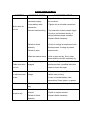
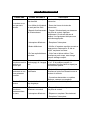
TROUBLE SHOOTING
SYMPTOM POSSIBLE CAUSE SUGGESTED ACTION
Motor does not
turn on
-Switch Assembly not
connected properly
-Loose battery cable
connections
-Solenoid malfunctioning
-Defective Switch
Assembly
-Defective motor
-Water has entered motor
-Insert Switch Assembly all the way into
the connector.
-Tighten nuts on all cable connections.
-Tap solenoid to loosen contacts. Apply
12 volts to coil terminals directly. A
clicking indicates proper activation.
-Replace Switch Assembly.
-Check for voltage at armature port with
Switch pressed. If voltage is present,
replace motor.
-Allow to drain and dry. Run in short
bursts without load until completely dry.
Motor runs but
Cable drum does
not turn
-Cam Ring (clutch) not
engaged
-Move Cam Ring to the “In” position. If
problem persists, a qualified technician
needs to check and repair.
Motor runs slowly
or without normal
power
-Insufficient current or
voltage
-Battery weak, recharge. Run winch with
vehicle motor running.
-Loose or corroded battery cable
connections. Clean, tighten, or replace.
Motor overheating
-Winch running time too
long
-Allow winch to cool down periodically.
Motor runs in one
direction only
-Defective or stuck
solenoid
-Defective Switch
Assembly
-Tap solenoid to loosen contacts.
-Repair or replace solenoid.
-Replace Switch Assembly.

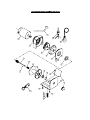
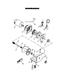
WINCH ASSEMBLY DRAWING
3
4
6
5
1
2
25
26
27
7
8
9
10
11
12
13
14
15
17
18
19
20
21
22
23
24
28
16

WINCH PARTS LIST
No. Part # Qty Description
1 200100 1 Motor
2 200200 1 Stationary Gear Housing Assembly
3 200300 1 Gear Carrier Assembly
4 200001 1 T-Series Rotator Gear
5 200002 1 Drum Support Plate
6 200003 4 Spring Washer Φ4 & Pan Head Screw M4 x 12
7 200004 1 Drum Support Bushing
8 200400 1 Clutch Assembly
9 200005 1 Spring
10 200006 1 Drum Assembly
11 200007 1 Screw M5 x 5
12 200008 1 T-Series Bushing
13 200009 1-2 Thick Flat Washer
14 200010 2 Hex Flange Nut M5
15 200011 1 T-Series Base Plate Assembly
16 200012 1 Tension Plate
17 200500 1 T-Series F/W Knob Assembly
18 200013 1 Elastic Pin 2.5 x 14
19 200014 2 Cap Screw M6 x 16
20 200015 2 Screw M5 x 10
21 200016 2 Screw M8 x 30
22 200017 2 Nut Φ8
23 200018 2 Washer -Flat Φ8
24 200019 2 Nut M8
25 200020 1 Hand Saver Bar
26 200600 1 Switch Assembly
27 200700 1 Cable Assembly
28 200800 1 Pulley Block

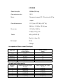
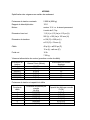
# C20049
Rated line pulls: 2000lbs (906 kgs)
Gear reduction ratio: 153:1
Motor: Permanent magnet DC 12V motor with 0.7hp
output
Overall dimensions: 11.2 “(L) x 4.13” (W) x 4.13” (H)
285 (L) x 110 (W) x 105 (H) mm
Drum size: 1.24” (D) x 2.88” (L)
31.5(D) x 73 (L) mm
Cable: 49’ (L) of 5/32” (D)
15m (L) of 4mm (D)
Net weight: 16 lbs
7.25 kgs
Line speed and Motor current (First layer)
Line Pull
Line Speed
Ft/min (m/min)
Motor Current
Amps
lb (kgs) 12V DC 12V DC
0 18(5.4) 12
500(227) 9.2(2.8) 25
1000(454) 7.5(2.3) 40
1500(680) 5.9(1.8) 60
2000(906) 3.3(1.3) 90
Line pull and Cable capacity
Layer of
Cable
Rated line pull per Layer
lb (kgs)
Cable Capacity per Layer
ft (m)
1 2000(906) 6.5(2.0)
2 1630(740) 14.0(4.3)
3 1380(620) 22.0(6.8)
4 1190(540) 31.0(9.5)
5 1050(480) 41.0(12.5)
6 940(420) 49.0(15.0)

Warranty
Champion Power Equipment
1 YEAR LIMITED WARRANTY
Effective September 1, 2006. Replaces all undated warranties and all warranties dated before September 1, 2006
Warranty Qualifications
Champion Power Equipment (CPE) will register this
warranty upon receipt of your Warranty Registration
Card and a copy of your sales receipt from one of
CPE's retail locations as proof of purchase.
Please submit your warranty registration and your
proof of purchase within ten (10) days of the date of
purchase.
Repair/Replacement Warranty
CPE warrants to the original purchaser that the
mechanical and electrical components will be free of
defects in material and workmanship for a period of
one (1) year from the original date of purchase (90
days for commercial & industrial use). Transportation
charges on product submitted for repair or
replacement under this warranty are the sole
responsibility of the purchaser. This warranty only
applies to the original purchaser and is not
transferable.
Do not return the unit to the place of
purchase
Contact CPE's Technical Service and CPE will
troubleshoot any issue via phone or e-mail. If the
problem is not corrected by this method, CPE will, at
its option, authorize evaluation, repair or replacement
of the defective part or component at a CPE Service
Center. CPE will provide you with a case number for
warranty service. Please keep it for future reference.
Repairs or replacements without prior authorization,
or at an unauthorized repair facility, will not be
covered by this warranty.
Warranty Exclusions
This warranty does not cover the following repairs
and equipment:
Normal Wear
Winches need periodic parts and service to perform
well. This warranty does not cover repair when
normal use has exhausted the life of a part or the
equipment as a whole.
Installation, Use and Maintenance
This warranty will not apply to parts and/or labor if
this winch is deemed to have been misused, neglected,
involved in an accident, abused, loaded beyond the
winch’s limits, modified, installed improperly or
connected incorrectly to any component. Normal
maintenance such as spark plugs, air filters,
adjustments, fuel system cleaning and obstruction
due to buildup is not covered by this warranty.
Other Exclusions
This warranty excludes:
• Cosmetic defects such as paint, decals, etc.
• Wear items such as filter elements, o-rings, etc.
• Accessory parts such as starting batteries, and
storage covers.
• Failures to due acts of God and other force majeure
events beyond the manufacturer’s control.
• Problems caused by parts that are not original
Champion Power Equipment parts.
Limits of Implied Warranty and
Consequential Damage
Champion Power Equipment disclaims any obligation
to cover any loss of time, use of this product, freight,
or any incidental or consequential claim by anyone
from using this winch. THIS WARRANTY IS IN LIEU
OF ALL OTHER WARRANTIES, EXPRESS OR
IMPLIED, INCLUDING WARRANTIES OF
MERCHANTABILITY OR FITNESS FOR A
PARTICULAR PURPOSE
A unit provided as an exchange will be subject to the
warranty of the original unit. The length of the
warranty governing the exchanged unit will remain
calculated by reference to the purchase date of the
original unit.
This warranty gives you certain legal rights which may
change from state to state. Your state may also have
other rights you may be entitled to that are not listed
within this warranty.
Contact Information
Address
Champion Power Equipment, Inc.
Customer Service
10006 Santa Fe Springs Rd.
Santa Fe Springs, CA 90670
Customer Service
Mon – Fri 8:30 AM – 5:00 PM (PST/PDT)
Toll Free: 1-877-338-0999
Fax no.: 1-562-236-9429
Technical Service
Mon – Fri 8:30 AM – 5:00 PM (PST/PDT)
Toll Free: 1-877-338-0999
tech@championpowerequipment.com

INTRODUCTION
Nous vous félicitons d’avoir choisi un treuil Champion. Nos treuils sont conçus
et fabriqués selon des normes rigoureuses. Aussi, leur usage et leur entretien
appropriés devraient vous assurer des années de loyaux services.
AVERTISSEMENT - Lire, apprendre et observer toutes les directives avant
de faire fonctionner ce dispositif. Le fait de ne pas respecter les instructions
pourrait entraîner des blessures corporelles ou des dommages matériels.
Ce treuil peut développer une formidable force de traction et pourrait causer
des dommages matériels, des blessures graves et même la mort s’il est utilisé
de façon irresponsable ou inadéquate. En parcourant ce manuel, vous trouverez
les symboles ci-dessous qui représentent des mises en garde et des
avertissements. Porter une attention toute spéciale aux notes accolées à ces
symboles, car elles ont été rédigées à des fins de sécurité. Enfin, l’utilisation
sécuritaire de cet appareil dépend d’abord de l’utilisateur.
Indique une situation potentiellement dangereuse qui, faute de
l’éviter, pourrait entraîner des blessures légères à modérées. On
l’utilise également comme mise en garde contre certaines
pratiques non sécuritaires.
Indique une situation potentiellement dangereuse qui, faute de l’éviter,
pourrait entraîner des blessures graves et même la mort.
ATTENTION

ACCESSOIRES COMPRIS AVEC LE TREUIL
DESCRIPTION QUANTITÉ
1. Treuil équipé et câble métallique 1
2. Boulons d’assemblage M8 x 30 2
3. Rondelles freins 2
4. Rondelles plates 2
5. Écrous M8 2
6. Moufle / Poulie coupée 1
7. Crochet à chape et goupille 1
8. Cordon / Interrupteur d’alimentation 1
9. Broche protège-mains 1
ACCESSOIRES NÉCESSAIRES
NON COMPRIS AVEC LE TREUIL
Gants – Pour manipuler le câble métallique et la sangle du crochet.
Chape / Manille en D – Pour relier la poulie coupée à la sangle d’ancrage.
Sangle d’ancrage / Chaîne – Les sangles d’ancrage protègent les arbres. Elles
sont faites de nylon de haute qualité qui offre une résistance élevée à la tension
(5 000 à 10 000 lb).
Couverture lourde – Pour placer sur le câble afin d’absorber l’énergie si ce
dernier venait à se rompre.

ASSEMBLAGE DU TREUIL
1.
1. Ce treuil CPE 2 000 lb présente une configuration à boulons très répandue
dans cette catégorie d’appareils. De nombreux nécessaires d’assemblage
comportant cette configuration sont offerts pour les VTT et profilés de fixation
les plus populaires. Si on ne parvient pas à trouver un nécessaire d’assemblage
dans une région, communiquer avec CPE pour obtenir les coordonnées du
détaillant le plus près.
2. Quel que soit le nécessaire d’assemblage utilisé, se placer sur une surface
plane pour procéder à l’assemblage du treuil afin que ses trois sections
principales, soit le moteur, le tambour et le système d’engrenage, se retrouvent
parfaitement alignés. Un alignement approprié permettra une distribution
uniforme de l’ensemble de la charge.
3. N’utiliser que les boulons M8 x 30, rondelles et écrous compris avec le treuil.
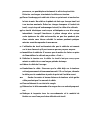
4. Relier les câbles du moteur à la batterie. Connecter le rouge (positif) à la
borne tournée vers l’extérieur du moteur et le noir (négatif) à la borne tournée
vers l’intérieur du moteur. Ensuite, connecter le câble rouge (positif) de
l’interrupteur à la borne positive (+) de la batterie 12 volts du véhicule, puis le
noir (négatif) à sa borne négative (-) (Fig. 1 et 2).
5. Fixer le crochet au câble. Tirer et tourner le bouton d’embrayage à la position
« Off » (roulement libre). Sortir un bout de câble du tambour. Retirer la goupille
du crochet à chape, passer l’œil du câble dans la chape, puis remettre la
goupille en place (Fig. 3 et 4).
6. Toujours utiliser la broche protège-mains au moment de bobiner le câble à la
main ou de le rembobiner (Fig. 7). Elle permet de garder mains et doigts à
bonne distance du tambour rotatif.
La page charge ...
La page charge ...
La page charge ...
La page charge ...
La page charge ...
La page charge ...
La page charge ...
La page charge ...
La page charge ...
La page charge ...
La page charge ...
La page charge ...
La page charge ...
-
 1
1
-
 2
2
-
 3
3
-
 4
4
-
 5
5
-
 6
6
-
 7
7
-
 8
8
-
 9
9
-
 10
10
-
 11
11
-
 12
12
-
 13
13
-
 14
14
-
 15
15
-
 16
16
-
 17
17
-
 18
18
-
 19
19
-
 20
20
-
 21
21
-
 22
22
-
 23
23
-
 24
24
-
 25
25
-
 26
26
-
 27
27
-
 28
28
-
 29
29
-
 30
30
-
 31
31
-
 32
32
-
 33
33


Champion Power Equipment 20049 Le manuel du propriétaire
- Taper
- Le manuel du propriétaire
- Ce manuel convient également à
dans d''autres langues
Documents connexes


Autres documents
-
Warn 87800 Guide d'installation
-
-
-
-
TrailFX WA008 Guide d'installation
-
Arctic Cat KIT-WINCH, PV3000 [PRLR] Manuel utilisateur
-
-
 Superwinch 1618201 Manuel utilisateur
-
Ingersoll-Rand PS10000RGC Mode d'emploi
-
