Epson BrightLink 475Wi Guide d'installation
- Taper
- Guide d'installation

Installation Guide
Guide d’installation

2
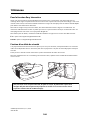
About This Installation Guide
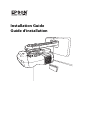
This guide describes how to mount the ultra-short-throw projectors listed below to a wall using the included
Epson® wall mount. It also explains how to install the Control Pad and Touch Unit after wall mount installation.
The following projectors are covered by this guide:
• BrightLink® 475Wi/480i/485Wi/575Wi/585Wi/595Wi and 575Wi+/585Wi+/595Wi+
• BrightLink Pro 1410Wi/1420Wi/1430Wi
• PowerLite® 470/475W/480/485W/570/575W/580/585W
Safety Instructions
For your safety, read all the instructions in this guide before using the wall mount. Incorrect handling that
ignores instructions in this guide could damage the wall mount or could result in personal injury or property
damage. Keep this installation guide on hand for future reference.
Read the safety instructions in the User's Guide for your projector and follow the instructions in this document.
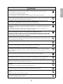
Explanation of Symbols
The warning marks shown below are used throughout this installation guide to prevent personal injury or
property damage. Make sure you understand these warnings when reading this installation guide.
Safety Precautions for Installation
This symbol indicates information that, if ignored, could possibly result in personal injury or even death
due to incorrect handling.
This symbol indicates information that, if ignored, could possibly result in personal injury or physical
damage due to incorrect handling.
This symbol indicates related or useful information.
Symbol indicating an action that must not be done
Symbol indicating an action that should be done
The wall mount is designed specifically for mounting a projector to a wall. If anything other than a
projector is mounted, the weight may result in damage.
If the wall mount falls, it could cause personal injury or property damage.
The installation work (wall mounting) should be performed by specialists who have technical knowledge
and ability. Incomplete or incorrect installation could cause the wall mount to fall and cause personal
injury or property damage.
Follow the instructions in this guide when installing the wall mount.
If the instructions are not followed, the wall mount may fall, resulting in personal injury or property damage.
Follow the instructions in this guide to install and operate the Touch Unit.
If the Touch Unit is not installed and operated properly, the light emitted from the laser could cause injury to
eyesight.
Warning
Caution
Warning

3
English
Handle the power cord carefully.
Incorrect handling may cause fire or electric shock. Observe the following precautions when handling:
• Do not handle the power plug with wet hands.
• Do not use a power cord that is damaged or modified.
• Do not pull the power cord with too much force when routing the cable through the wall mount.
Do not install the wall mount in a place where it might be subjected to vibration or shock.
Vibration or shock could cause damage to the projector or mounting surface. It could also cause the wall mount or
projector to fall and cause personal injury or property damage.
The installation work should be performed by at least two qualified service personnel. If you need to
loosen any screws during installation, be careful not to drop the wall mount.
If the wall mount or projector falls, it could cause personal injury or property damage.
Install the wall mount so that it can sufficiently support the weight of the projector and wall mount, and
resist any horizontal vibration. Use M10 nuts and bolts and make sure to use appropriate wall anchors for
your wall type.
Nuts and bolts smaller than M10 could cause the wall mount to fall. Epson accepts no responsibility for any
damage or injury caused by lack of wall strength or inadequate installation.
When you mount the projector on the wall with the wall mount, the wall must be strong enough to hold the
projector, the wall mount, as well as the Control Pad and the Touch Unit, if necessary.
This wall mount should be installed on a concrete wall. Confirm the weight of the projector, the wall mount,
the Control Pad, and the Touch Unit before installation, and maintain the strength of the wall. If the wall is
not strong enough, reinforce the wall before installation.
Inspect the wall mount on a regular basis to ensure there are no broken parts or loose screws.
If there are any broken parts, stop using the wall mount immediately. If the wall mount or projector falls, it could
cause personal injury or property damage.
Never modify the wall mount, Control Pad, or Touch Unit.
Do not hang on the wall mount or hang a heavy object on the wall mount.
If the projector or wall mount falls, it could cause personal injury or property damage.
Do not use adhesives, lubricants, or oils to install or adjust the wall mount.
If you use adhesives to prevent the screws from loosening or things such as lubricants or oils on the part of the
projector attached to the slide plate, the case may crack and cause the projector to fall, resulting in personal injury
or property damage.
Tighten all screws firmly after adjustment.
Otherwise, the projector or wall mount may fall and cause personal injury or property damage.
Never loosen the bolts and nuts after installation.
Confirm that the screws have not become loose on a regular basis. If you find any loose screws, tighten them
firmly. Otherwise, the projector or wall mount may fall and cause personal injury or property damage.
When performing wiring, make sure the cable does not come into contact with any screws or bolts.
Handling the cable incorrectly may cause fire or electric shock.
Do not apply optical devices such as a magnifying glass or telescope to the laser light diffused from the
Touch Unit.
If such optical devices are applied, it could cause personal injury or fire.
Do not look into the Touch Unit’s laser diffusion ports.
This could cause injury to eyesight. Extra care should be taken when children are present.
Do not view the laser light using optical devices such as a magnifying glass within a range of 2.75 inches
(70 mm).
Viewing at close range could cause injury to eyesight.
Connect the Touch Unit to BrightLink 595Wi/595Wi+ and BrightLink Pro 1430Wi models only. Do not
connect it to any other projectors or devices.
Warning

4
Installation Location
• Before installing the projector, verify the power supply wiring for the installation location.
• Install the projector away from other electric devices such as fluorescent lights or air conditioners. Some
kinds of fluorescent lights could interfere with the remote control of the projector.
• Install the projector away from direct sunlight and other bright light sources.
• It is recommended to keep VGA computer cable length less than 65 ft (20 meters) to reduce external
noise.
• Install the projector in a location where the projected image is within reach.
• The projector must be installed in one of the following locations in order for the Touch Unit to function
properly:
• Mounted on a wall or suspended from the ceiling with images projected from in front of the screen.
• Mounted vertically on a table with images projected from the front of the table. If using this
installation method, you need the optional interactive table mount (ELPMB29) and attachment plate
(ELPPT05).
• When powering the Control Pad using batteries, verify that the installation location meets the following
conditions:
• Install the Control Pad on the same surface as the projection screen. If the projection screen and the
Control Pad installation point are uneven, install the Control Pad approximately 8 in (20 cm) from the
edge of the screen.
• Make sure there are no obstacles between the Control Pad and the projector (not including the Touch
Unit).
• Use the optional Remote Control Cable Set (model ELPKC28, part number V12H005C28) to supply power
to the Control Pad in the following situations:
• The required conditions above are not met.
• The projection screen and the Control Pad installation point are uneven and the difference in height is
more than 2 inches (5 cm).
• The projector is placed on a table and projecting to the screen.
• Multiple projectors are being used.
Do not use the Touch Unit if you are using or near medical equipment such as a pacemaker.
The magnet within the Touch Unit generates electromagnetic interference which could cause medical equipment
to malfunction.
Do not install the wall mount in a location where the operating temperature for your projector model may
be exceeded. Such an environment may damage the projector.
Install the wall mount in a place free from excessive dust and humidity to prevent the lens or optical
components from becoming dirty.
Do not use excessive force when adjusting the wall mount.
The wall mount may break, resulting in personal injury.
Keep magnetic storage media (for example, magnetic cards or electronic devices such as computers,
digital watches, or cell phones) away from the Touch Unit.
The magnet within the Touch Unit generates electromagnetic interference which could corrupt data or cause the
media or device to malfunction.
Warning
Caution

5
English
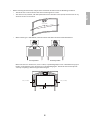
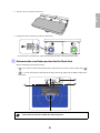
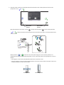
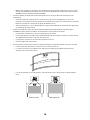
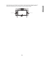
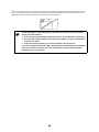
• Before installing the Touch Unit, verify that the installation location meets the following conditions:
• The Touch Unit can be secured to the surface with magnets or screws.
• The surface is flat, smooth, and unwarped with no more than 0.2 inches (5 mm) of unevenness in any
direction on the screen surface.
• When installing on a whiteboard, install the Touch Unit within the frame of the whiteboard.
Make sure there are no obstacles, such as cables, or protruding objects such as whiteboard trays, pen
holders, or thick frames in the shaded areas in the following figure. The Touch Unit will not operate
correctly if anything is obstructing the infrared signal.
0.2 in. (5 mm)
Correct position Incorrect position
0.8 in. (20 mm)
4.0 in. (100 mm)4.0 in. (100 mm)

6
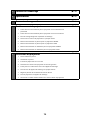
1 Package Contents
s 8
2 Specifications
s 10
3 Connecting Devices
s 14
4 Positioning the Projector
1. Installation worksheet for projecting on a pre-installed wall-mounted board
2. Installation worksheet for projecting on a plain wall
3. Diagonal image size and mounting position
4. Distance from projection surface to wall plate
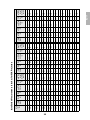
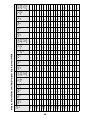
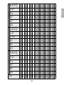
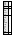
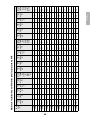
5. Installation measurement tables
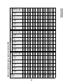
6. Installation Measurements in Inches for WXGA Projectors
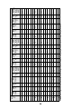
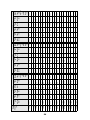
7. Installation Measurements in Inches for XGA Projectors
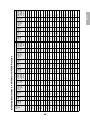
8. Installation Measurements in Millimeters for WXGA Projectors
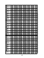
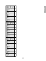
9. nstallation Measurements in Millimeters for XGA Projectors
s 16
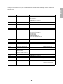
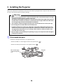
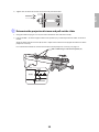
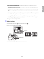
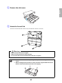
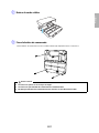
5 Installing the Projector
1. Disassemble the parts
2. Assemble the parts
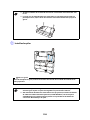
3. Install the wall plate on the wall
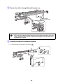
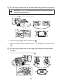
4. Determine the projection distance and pull out the slider
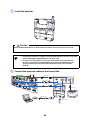
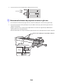
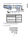
5. Route the cables through the wall mount arm
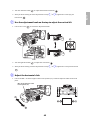
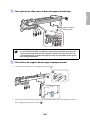
6. Attach the mount arm to the wall plate
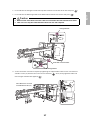
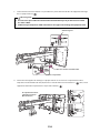
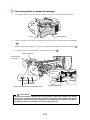
7. Adjust the vertical slide position of the arm
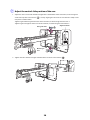
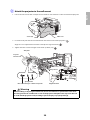
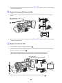
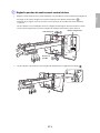
8. Attach the projector to the wall mount
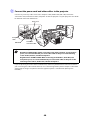
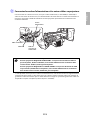
9. Connect the power cord and other cables to the projector
s 30

7
English
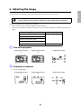
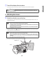
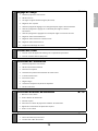
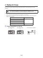
6 Adjusting the Image
1. Turn on the projector
2. Display the test pattern
3. Change the aspect ratio if necessary
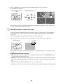
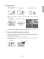
4. Adjust the focus
5. Use the adjustment knob on the left side to adjust the horizontal roll
6. Use the adjustment knob on the right side to adjust the horizontal rotation
7. Use the adjustment knob on the top to adjust the vertical tilt
8. Adjust the horizontal slide
9. Adjust the forward/backward slide
10. Adjust the vertical slide
11. Turn off the display of the test pattern
s 41
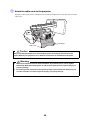
7 Attaching the Covers
1. Attach the wall plate cover and end cap
2. Attach the cable cover to the projector
s 47
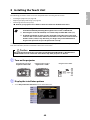
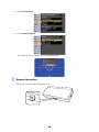
8 Installing the Touch Unit
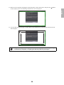
1. Turn on the projector
2. Display the installation pattern
3. Remove the markers
4. Determine the installation position for the Touch Unit
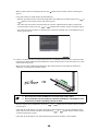
5. Install the Touch Unit
6. Connect the cable
7. Adjust the angle
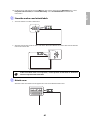
8. Store the markers and attach labels
9. Attach cover
s 49
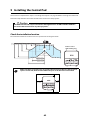
9 Installing the Control Pad
1. Remove the cable cover
2. Attach the Control Pad
3. Install the batteries
4. Connect the projector cables to the Control Pad
5. Attach the port protection stickers
6. Attach the cable cover
s 62
10 Appendix
1. Using the Easy Interactive Function
2. Attaching a Security Cable
s 66

8
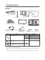
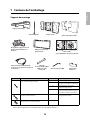
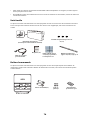
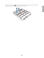
1 Package Contents
Wall Mount
• Use the bolts or screws supplied with the wall mount to install it as directed in this guide. Do not
substitute these bolts with any other types.
• You need to use commercially available M10 × 60 mm anchors (at least 3) to attach the wall plate to the
wall.
• Gather the tools and parts you need before you begin installation, including a #3 cross-head screwdriver.
Shape Name Quantity Application
M4 × 12 mm hexagon socket head cap bolt with
washer/spring washer
6 For wall plate assembly
4 For 3-axis adjustment unit/wall mount
installation
4 For slide plate/projector installation
2 For slide plate/3-axis adjustment unit
installation (secured when shipped)
M6 × 20 mm hexagon shoulder bolt with washer/
spring washer
1 For wall mount/wall plate installation
M6 × 20 mm cross recessed head shoulder screw
with plastic washer
3
Hexagon wrench (for M4)
Wall plate cover
Wall mount
Template sheet
(for installing the wall plate)
End cap
3-axis adjustment unit and slide
plate (attached when shipped)
Open-ended wrench
13 mm (for M8 and M6) ×
6 mm (for hexagonal
shaft)
Wall plate
VGA computer cable (may be included
with projector or wall mount)
Hexagonal shaft
Wall plate cover extender

9
English
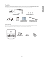
Touch Unit
The following parts are packaged with your projector and are necessary when attaching the Touch Unit. When
installing the Touch Unit on a non-magnetic surface, you will also need three M4 screws.
Control Pad
The following parts are packaged with your projector and are necessary when attaching the Control Pad.
When installing the Control Pad on a wall, you will also need four M4 × 20 mm screws.
Tape (approx. 2.4 inches
[6 cm]) for securing the
markers (×12)
Label (×4)
Touch Unit and markers
(markers are inside the unit)
Touch Unit connection cable
Infrared deflector (approx.
11.2 inches [28.5 cm]) (×8)
Spacer for screw hole (×3)
AA size batteries (× 2) Port protection
stickers
Control Pad
Rubber feet

10
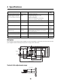
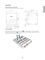
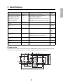
2Specifications
Wall plate
The wall plate is in three pieces when shipped. Use the included M4 × 12 mm bolts (×6) to attach the separate
pieces together before mounting the projector. See page 31 for instructions.
Vertical slide adjustment range
Item Specification Additional information Reference
Page
Wall mount weight (including the
3-axis adjustment unit, slide plate,
wall plate, wall plate cover, wall
plate cover extender, and end cap)
Approx. 18.5 lb
(8.4 kg)
Wall mount: 6.6 lb (3.0 kg)
3-axis adjustment unit: 2.6 lb (1.2 kg)
Slide plate: 1.8 lb (0.8 kg)
Wall plate: 6.0 lb (2.7 kg)
Wall plate cover and end cap: 0.9 lb (0.4 kg)
Wall plate cover extender: 0.6 lb (0.3 kg)
—
Maximum load capacity 15.4 lb (7 kg) — —
Vertical slide adjustment range ± 1.5 in. (38 mm) — Refer to the
illustration
below
Horizontal slide adjustment range ± 1.8 in. (45 mm) — Refer to the
illustration on
page 11
Forward/backward slide
adjustment range
0 to 14.2 in.
(360 mm)
Arm slide adjustment range: 0 to 10.7 in. (273 mm)
Adjustment from 3-axis adjustment unit installation
position: 3.4 in. (87 mm)
Refer to the
illustration on
page 11
Horizontal roll adjustment range ± 3° Fine adjustments possible with adjustment knob
s p. 44
Horizontal rotation adjustment
range
± 8° Fine adjustments possible with adjustment knob
s p. 44
Vertical tilt adjustment range ± 3° Fine adjustments possible with adjustment knob
s p. 45
5.1 in.
(130 mm)
1.0 in.
(25 mm)
1.3 in.
(33 mm)
3.2 in.
(80 mm)
4.2 in.
(106.5 mm)
3.1 in.
(79 mm)
2.4 in.
(60 mm)
4.6 in. (117 mm)
8.8 in. (223 mm)
6.3 in. (160 mm)
8.4 in. (213 mm)
19.5 in. (496 mm)
8.7 in. (222 mm)
9.7 in. (246 mm)
1.2 in.
(30.6 mm)
1.5 in. (38 mm)
1.5 in. (38 mm)

11
English
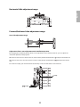
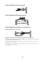
Horizontal slide adjustment range
Forward/backward slide adjustment range
Arm slide adjustment range
Adjustment from 3-axis adjustment unit installation position
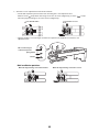
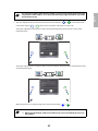
By changing the installation position of the 3-axis adjustment unit to the front or back, you can adjust the
installation position of the projector.
When the screen size is less than 75 inches, install it at the position marked with a stamp on the mount arm.
When the screen size is 75 inches or more, install it at the position marked with a stamp on the mount
arm.
To see these stamps, you need to remove the two top screws and slide out the arm extension.
1.8 in. (45 mm)
1.8 in. (45 mm)
10.7 in. (273 mm)
3.4 in.
(87 mm)
Stamp
Stamp

12
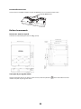
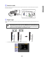
Touch Unit
External dimensions and weight
The Touch Unit weighs approximately 16 ounces (450 g).
Attached labels
The Touch Unit is a Class 1 laser product that conforms to the JIS C 6802:2011 standard. There are warning
labels affixed to the Touch Unit to indicate that it is a Class 1 laser product. The labels contain the following
information:
• Invisible laser radiation
• Do not view the beam directly with optical instruments
• Class 1 laser product
Laser diffusion port
The laser beam is diffused from the laser diffusion ports on the back of the Touch Unit.
8.3 in. (210 mm)
3.7 in. (95 mm)
2.0 in.
(51 mm)
Laser diffusion ports

13
English
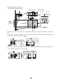
Control Pad
External dimensions and weight
The Control Pad weighs approximately 8.5 ounces (240 g).
Cable routing holes
When routing cables through a wall, use the position ( ) in the following figure as the cable routing hole.
Otherwise, remove the cable cover ( ) and route the cables through the opening. Route the printer cable
along the groove on the back of the Control Pad.
5.4 in (135.9 mm)
0,6 in
(15.47 mm)
0.1 in (3.5 mm)
5.9 in (149 mm)
1.1 in
(29 mm)
4.2 in (107 mm)
4.0 in (104 mm)
1.2 in
(30.9 mm)
6.0 in (153.5 mm)
0.4 in
(11.5 mm)
4.3 in (109 mm)
4.4 in (111 mm)

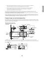
14
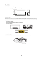
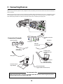
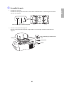
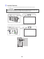
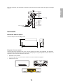
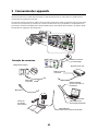
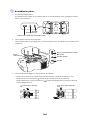
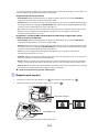
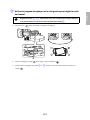
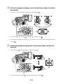
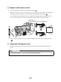
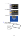
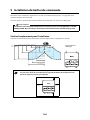
3Connecting Devices
Make sure you have the power cord, computer cable, and other parts at the location where the wall mount is
to be installed.
Make sure you also have all necessary cables for the Touch Unit and other devices, such as a document camera
or microphone, that you will connect to the projector. Your projector’s connection panel may differ slightly
from the displayed model. For details, refer to the online User’s Guide for your projector.
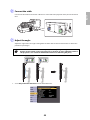
External speakers
LAN device
Microphone
USB cable (for Easy
Interactive Function)
Document camera
(Epson DC-06)
Computer
Computer cable
(for computer video
output)
Connection Example
Dedicated USB cable
(supplied with document camera)
Audio cable
(not included)
LAN cable
(not included)
Touch Unit connection
cable
Touch Unit
When interacting with a computer, you need a USB cable. However, when using the projector's
built-in toolbar, you do not need a USB cable.
For Interactive Use

15
English
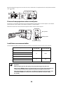
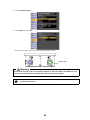
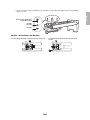
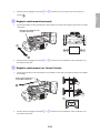
Connecting the Control Pad
The Control Pad is included with the BrightLink Pro 1410Wi/1420Wi/1430Wi projectors. It provides a
convenient alternative to the remote control for turning on the projector, changing the source, and selecting
whiteboard mode. You can also use the control pad to capture, print, and save your projected images.
You must install the control pad on the same surface as the projector, within the range specified in the
installation instructions. You can use the included batteries to power the control pad, or the optional remote
control cable set (model ELPKC28, part number V12H005C28).
See ”Installing the Control Pad” on page 62 for instructions.

16
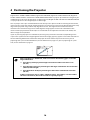
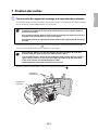
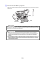
4 Positioning the Projector
BrightLink Pro 1410Wi/1420Wi/1430Wi, BrightLink 475W/485W, BrightLink 575Wi/585Wi/595Wi, BrightLink
575Wi+/585Wi+/595Wi+ and PowerLite 475W/485W/575W/585W can project up to 100 inches diagonally for
a WXGA image or 88 inches diagonally for an XGA image. The BrightLink 480i and PowerLite 470/480/570/580
can project up to 93 inches diagonally for an XGA image.
You can project onto a pre-installed whiteboard or directly onto a plain wall. When installing the Touch Unit,
install it on the screen that is being used for projection; you need at least 4.7 inches (120 mm) between the top
edge of the projected image and the top edge of the screen. The height of the included wall mount
determines the maximum image size and how high the image appears on the wall or whiteboard. The
distance of the projector from the wall (once it is mounted on the adjustable arm of the wall mount) also
affects image size and position.
If you are planning to project on a whiteboard, the image may not fill the entire board, depending on the
aspect ratio. If you match the image height to the board’s height, gaps may appear on the sides of the board.
Use the following worksheets to determine the proper location of the wall plate on the wall. If you are
projecting onto a pre-installed whiteboard, use the worksheet on page 17. If you are projecting on a plain
wall, use the worksheet on page 18.
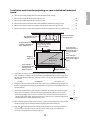
When installing on a whiteboard, make sure to leave the following gaps around the
edge of the board:
❏ From the top of the projected image to the bottom of the Touch Unit: 1 inch
(25 mm)
❏ From the edges of the projected image to the edges of the board: at least 4 inches
(100 mm) left and right
❏ From the bottom of the projected image to the bottom of the board: 0.8 inches
(20 mm)
If there are obstacles such as cables, whiteboard trays, pen holders, or frames within
the areas listed above, the Touch Unit will not operate properly.

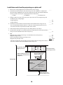
17
English
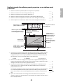
Installation worksheet for projecting on a pre-installed wall-mounted
board
1. Measure the ceiling height (distance from the floor to the ceiling). _____
2. Measure the height of the board’s image area (h). _____ (h)
3. Measure the width of the board’s image area (w). _____ (w)
4. Measure the distance from the floor to the bottom of the board’s image area (f). _____ (f)
5. Measure the distance from the ceiling to the top of the board’s image area (d). _____ (d)
6. Measure the thickness of the board (distance from the projection surface to the wall) (x). _____ (x)
7. Determine the aspect ratio of the board or of the images that will be projected. For
new computers or laptops, this will most likely be WXGA (16:10). For older equipment,
this will most likely be XGA (4:3). You may need to consult your IT department for this
information.
___ 4:3 XGA ___ 16:10 WXGA ___ 16:9 Widescreen
8. Using the tables on pages 21 to 28 for your aspect ratio and desired image height (h),
find the required distance between the top of the image area and the bottom holes of
the wall plate (c).
_____ (c)
9. Determine the position for your projector installation by adding the values for (f), (h),
and (c), plus an additional 10 inches for the height of the wall plate plus the cover.
If the ceiling height of your room (as noted in step 1) does not meet the minimum
ceiling height required for your board, you may need to select a smaller image size or
move the board to a lower position on the wall.
_____ (f)
_____ (h)
_____ (c)
+10
inches
_____ total
10. After confirming your image size, use tape or a pencil to mark the distance (c) from the
top of the image area on the board to the bottom holes of the wall plate.
11. Align the line (horizontal) on the template sheet with the (c) mark, then align the
center line on the template sheet with the center of the image area. Follow the
instructions on page 30 to install the projector.
10 in. (254 mm)—height of
wall plate plus cover
Required distance from top
of image area to bottom
holes of wall plate (c)
Diagonal size of
image area (S)
Height of
image area (h)
Distance from ceiling to
top of image area (d)
Width of image area (w)
Distance from floor to
bottom of image area (f)
4.0 in. (100 mm)—
distance from edge of
image area to edge of
board
1.0 in. (25 mm)—distance
from top of image area to
bottom of Touch Unit
0.8 in. (20 mm)—
distance from bottom
of image area to
bottom of board
4.7 in. (119 mm)—
distance from top of
image area to top of
board (Touch Unit
only)

18
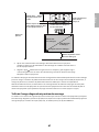
Installation worksheet for projecting on a plain wall
1. Measure the ceiling height (distance from the floor to the ceiling). _____
2. Determine the desired aspect ratio of the image. For new computers or laptops, this
will most likely be WXGA (16:10). For older equipment, this will most likely be XGA (4:3).
You may need to consult your IT department for this information.
___ 4:3 XGA ___ 16:10 WXGA ___ 16:9 Widescreen
3. Using the tables on pages 21 to 25 for your aspect ratio, select the largest image size
available for your ceiling height.
Image height (h)
Image width (w)
_____ (h)
_____ (w)
4. Determine the desired distance from the floor to the bottom of the image area (f).
The recommended minimum distance is 30 inches. Images appearing less than 28
inches from the floor may be obstructed for some viewers.
_____ (f)
5. Find the top of the projected image area by adding distances (f) and (h). _____
6. Use the tables on pages 21 to 28 to determine the required distance from the top of the
image area to the bottom holes of the wall plate (c). _____ (c)
7. Add:
Required distance from top of image area to bottom holes of wall plate (c)
Height of image area (h)
Distance from floor to bottom of image area (f)
Height of wall plate plus cover
If the total exceeds the ceiling height, you will need to reduce the image size or reduce
the distance from the floor to the bottom of the image area.
_____ (c)
_____ (h)
_____ (f)
+10
inches
_____ total
10 in. (254 mm)—height of
wall plate plus cover
Required distance from top of
image area to bottom holes of
wall plate (c)
Diagonal size of
image area (S)
Height of
image area (h)
Distance from ceiling
to top of image area (d)
Width of image area (w)
Distance from floor to
bottom of image area (f)
1 in. (25 mm)—distance
from top of image area to
bottom of Touch Unit
Ceiling height

19
English
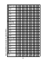
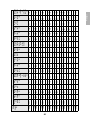
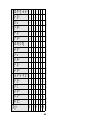
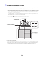
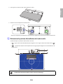
The tables on the following pages provide installation information for all supported image sizes. The
minimum ceiling height is based on an image 30 inches from the floor; if the image is lower, the minimum
ceiling height is reduced by the corresponding measurement.
Use the worksheets, the illustrations, and the information in the tables on the following pages to determine
the projection distance and placement of the wall plate. The recommended range for projection distance (a)
as shown on the following pages is 2.5 to 12.2 inches (62 to 311 mm).
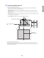
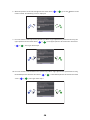
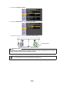
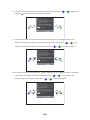
Diagonal image size and mounting position
The numbers on the slider measure (b) are the same as the projection distance (a) when the diagonal image
size (S) is 75 inches or more. Because the installation position of the projector changes when (S) is less than 75
inches, the numbers for (a) and (b) differ.
In order to see the stamp and the numbers on the slider scale, you need to slide out the arm extension.
When the diagonal image size is 75 inches or more, mount the 3-axis adjustment unit at the position marked
with a stamp.
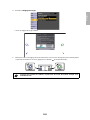
8. After confirming your image size, use tape or a pencil to mark the distance (c) from the
top of the image area on the board to the bottom holes of the wall plate.
9. Align the line (horizontal) on the template sheet with the (c) mark, then align the
center line on the template sheet with the center of the image area. Follow the
instructions on page 30 to install the projector.
Wall plate
Projection
surface
Offset value for the position of the
center of the screen and the center of
the wall plate
Distance from wall to
projection surface
2.8 in. (70.5 mm)
8.6 in.
(218 mm)
Height of
projected
image
4.0 in. (100 mm)
1 in. (25 mm)
0.8 in. (20 mm)
1.2 in. (30.6 mm)
4.7 in. (120 mm)

20
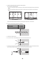
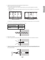
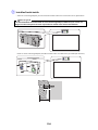
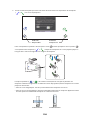
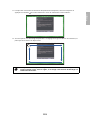
When the diagonal image size is less than 75 inches, mount the 3-axis adjustment unit at the position marked
with a stamp.
Distance from projection surface to wall plate
The distance (c) from the projection surface to the bottom mounting holes on the wall plate is the number
given when the vertical slide is set to the base position, as shown below.
Match the notch on the wall mount to the position of the stamp on the wall plate.
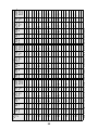
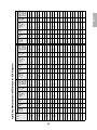
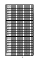
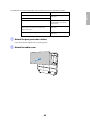
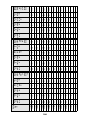
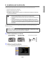
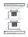
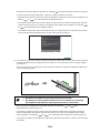
Installation measurement tables
Use the following table to determine which installation measurement table to use for your projector.
Projector model Maximum image
size (diagonal)
Installation
measurement table
BrightLink Pro 1410Wi/1420Wi/1430Wi
100 WXGA
BrightLink 475W/485W/575Wi/585Wi/595Wi
BrightLink 575Wi+/585Wi+/595Wi+
PowerLite 475W/485W/575W/585W
BrightLink 480i
93 XGA
PowerLite 470/480/570/580
The measurements may differ depending on the location where you place the
projector.
When projecting in Tele, the quality of the projected images may decrease.
When using a WXGA projector to project images at a 4:3 aspect ratio, the images are
resized automatically and the quality of the projected images may decrease.
When the wall plate cover extender is installed, the minimum diagonal image size is
increased to: WXGA 67” (16:10), 65” (16:9), 59” (4:3); XGA 62” (4:3), 57” (16:9),
59”(16:10).
Base position
Stamp on plate
Notch on mount arm
La page charge ...
La page charge ...
La page charge ...
La page charge ...
La page charge ...
La page charge ...
La page charge ...
La page charge ...
La page charge ...
La page charge ...
La page charge ...
La page charge ...
La page charge ...
La page charge ...
La page charge ...
La page charge ...
La page charge ...
La page charge ...
La page charge ...
La page charge ...
La page charge ...
La page charge ...
La page charge ...
La page charge ...
La page charge ...
La page charge ...
La page charge ...
La page charge ...
La page charge ...
La page charge ...
La page charge ...
La page charge ...
La page charge ...
La page charge ...
La page charge ...
La page charge ...
La page charge ...
La page charge ...
La page charge ...
La page charge ...
La page charge ...
La page charge ...
La page charge ...
La page charge ...
La page charge ...
La page charge ...
La page charge ...
La page charge ...
La page charge ...
La page charge ...
La page charge ...
La page charge ...
La page charge ...
La page charge ...
La page charge ...
La page charge ...
La page charge ...
La page charge ...
La page charge ...
La page charge ...
La page charge ...
La page charge ...
La page charge ...
La page charge ...
La page charge ...
La page charge ...
La page charge ...
La page charge ...
La page charge ...
La page charge ...
La page charge ...
La page charge ...
La page charge ...
La page charge ...
La page charge ...
La page charge ...
La page charge ...
La page charge ...
La page charge ...
La page charge ...
La page charge ...
La page charge ...
La page charge ...
La page charge ...
La page charge ...
La page charge ...
La page charge ...
La page charge ...
La page charge ...
La page charge ...
La page charge ...
La page charge ...
La page charge ...
La page charge ...
La page charge ...
La page charge ...
La page charge ...
La page charge ...
La page charge ...
La page charge ...
La page charge ...
La page charge ...
La page charge ...
La page charge ...
La page charge ...
La page charge ...
La page charge ...
La page charge ...
La page charge ...
La page charge ...
La page charge ...
La page charge ...
La page charge ...
La page charge ...
La page charge ...
La page charge ...
La page charge ...
La page charge ...
La page charge ...
La page charge ...
-
 1
1
-
 2
2
-
 3
3
-
 4
4
-
 5
5
-
 6
6
-
 7
7
-
 8
8
-
 9
9
-
 10
10
-
 11
11
-
 12
12
-
 13
13
-
 14
14
-
 15
15
-
 16
16
-
 17
17
-
 18
18
-
 19
19
-
 20
20
-
 21
21
-
 22
22
-
 23
23
-
 24
24
-
 25
25
-
 26
26
-
 27
27
-
 28
28
-
 29
29
-
 30
30
-
 31
31
-
 32
32
-
 33
33
-
 34
34
-
 35
35
-
 36
36
-
 37
37
-
 38
38
-
 39
39
-
 40
40
-
 41
41
-
 42
42
-
 43
43
-
 44
44
-
 45
45
-
 46
46
-
 47
47
-
 48
48
-
 49
49
-
 50
50
-
 51
51
-
 52
52
-
 53
53
-
 54
54
-
 55
55
-
 56
56
-
 57
57
-
 58
58
-
 59
59
-
 60
60
-
 61
61
-
 62
62
-
 63
63
-
 64
64
-
 65
65
-
 66
66
-
 67
67
-
 68
68
-
 69
69
-
 70
70
-
 71
71
-
 72
72
-
 73
73
-
 74
74
-
 75
75
-
 76
76
-
 77
77
-
 78
78
-
 79
79
-
 80
80
-
 81
81
-
 82
82
-
 83
83
-
 84
84
-
 85
85
-
 86
86
-
 87
87
-
 88
88
-
 89
89
-
 90
90
-
 91
91
-
 92
92
-
 93
93
-
 94
94
-
 95
95
-
 96
96
-
 97
97
-
 98
98
-
 99
99
-
 100
100
-
 101
101
-
 102
102
-
 103
103
-
 104
104
-
 105
105
-
 106
106
-
 107
107
-
 108
108
-
 109
109
-
 110
110
-
 111
111
-
 112
112
-
 113
113
-
 114
114
-
 115
115
-
 116
116
-
 117
117
-
 118
118
-
 119
119
-
 120
120
-
 121
121
-
 122
122
-
 123
123
-
 124
124
-
 125
125
-
 126
126
-
 127
127
-
 128
128
-
 129
129
-
 130
130
-
 131
131
-
 132
132
-
 133
133
-
 134
134
-
 135
135
-
 136
136
-
 137
137
-
 138
138
-
 139
139
-
 140
140


Epson BrightLink 475Wi Guide d'installation
- Taper
- Guide d'installation
dans d''autres langues
Documents connexes
-
Epson Europe EB-1430Wi Manuel utilisateur
-
Epson BrightLink Pro 1470Ui Guide d'installation
-
-
Epson PowerLite 685W for SMART Guide d'installation
-
Epson BrightLink Solo Interactive Module Guide d'installation rapide
-
-
-
Epson BrightLink 595Wi Guide d'installation
-
Epson BrightLink Pro 1410Wi Supplement
-
Epson V11H281020 - PowerLite 400W WXGA LCD Projector Mode d'emploi
Autres documents
-
Casio YM-81 Mode d'emploi
-
Casio YM-80 Mode d'emploi
-
Kimex 016-1601 Guide d'installation
-
-
NEC NP-UM383WL-WK Le manuel du propriétaire
-
Sharp ANSV100T Mode d'emploi
-
MCL 8SP-TAB Fiche technique
-
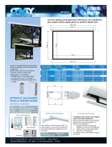 ORAY OPTCOMMANDRAD5 Fiche technique
-
Elite Screens ZRM-135HW-CINEGREY5D Guide d'installation
-
 SCS Sentinel 3245060990107 Le manuel du propriétaire

