
1
No: IS-0630 – Rev. A
1
Wattstopper
®
Daylight Sensor - EM Light Sensor
Installation Instructions
No: IS-0630– Rev. 1
EM-LIGHTSENSOR
Country of Origin: Made in China
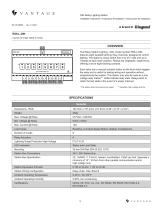
SYSTEM REQUIREMENTS
OVERVIEW
The Vantage EM-LIGHTSENSOR measures the intensity of light in an area and allows the
Vantage system to automatically adjust lighting xtures and blinds to maintain a consistent level
of light. For example, during the day as lighting levels in a room change, lighting xtures may
be programmed to dim or brighten. Natural light can be used to limit articial light, maximizing
energy savings, by closing or opening blinds to help maintain a predetermined ambient light
level. In the evening, lighting xtures may be programmed to automatically brighten, replacing the
light lost by the setting sun.
The Vantage EM-LIGHTSENSOR also behaves like a photocell turning lights on or off at a
preset level of light. In some cases (business signs, outside security lights, corridors, etc.),
lighting is desired during overcast conditions and not just at dusk or dawn. With the Vantage EM-
LIGHTSENSOR, an outdoor company sign that turns on at dusk could also be set to illuminate
during heavy cloud cover.
The Vantage EM-LIGHTSENSOR is designed to be virtually unnoticeable. The spectrum of light
measured is “Visible Light”. The scale is nearly innite ranging from 0 through 10,000fc. This
allows light samples from indoor and outdoor locations. Note: the EM-LIGHTSENSOR must be
protected from the elements if installed to measure outdoor light.
The EM-LIGHTSENSOR is compatible with InFusion Design Center software or QLink software 3.0 with Controller rmware version
5.91 or higher. For new projects it is recommended that rmware and software be kept to the most current release.
Description Specication
Dimensions, (Diam. x H) Overall: 2.0 in x 1.6 in (51mm x 41mm)
Finished: 2.0 in x 0.16 in (51mm x 4 mm)
Color White
Mounting Ceiling or wall mountable
Optimum Mounting Height 8 ft (2.5 m)
Directional Detection Pattern Rotate for light source reading
Voltage 12VDC
Current Draw 10mA
Ambient Operating Temperature 32 - 95°F (0 - 35°C)
Ambient Operating Humidity 5 - 95% non-condensing
SPECIFICATIONS

2
No: IS-0630 – Rev. A
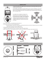
4. Cut a round, 29mm (1.125”) diameter hole in the sheet rock.
5. Connect the wires to the sensor as illustrated above.
a. Squeeze the grips on either side of the sensor and carefully slide part way into the hole making sure the sensor is straight
up/level with the ceiling or wall (see diagram below).
6. Test operation before pushing all the way into the ceiling or wall.
7. Rotate the cutaway section of the face, if necessary, to get the best light readings.
8. After completing tests, nish pushing the sensor in the hole until it is ush with the ceiling or wall as illustrated below.
CORRECT
WRONG WAY
INSTALLATION
1. To minimize possible false triggering, try to place the sensor where direct sunlight does not hit
it (unless you want it to). Be aware of reective surfaces that may reect light sources generating
unwanted light measurements.
2. The sensor is connected to the Vantage system by three (3) wires, Output/Sensor, Ground and
Power. The three wires connect to button 10 on a keypad or contact 10 on a CIS (Contact Input
Station). A six wire pigtail is used when connecting to the back of a keypad and direct wiring is used
when connecting to a CIS.
SENSORGND
+12VDC
(10mA)
3. The light sensor is designed to read light more
effectively using a directional cutaway design in the
face of the sensor. By rotating the cutaway section on
the face of the sensor, in a 360° circle, it is possible to
maximize the sensor’s light input from any direction.
It still picks up light from other directions but is more
sensitive to the direction of the cutout channel in the
face design.
MULTI-VIEW LINE DRAWING
2.0" 1.0"
1.6" 0.875"

800.555.9891
www.legrand.us/wattstopper
No. IS-0630 – rev. 1
© Copyright 2018 Legrand All Rights Reserved.
© Copyright 2018 Tous droits réservés Legrand.
© Copyright 2018 Legrand Todos los derechos reservados.
Wattstopper warranties its products to be free
of defects in materials and workmanship for a
period of five (5) years. There are no obligations
or liabilities on the part of Wattstopper for
consequential damages arising out of, or in
connection with, the use or performance of this
product or other indirect damages with respect
to loss of property, revenue or profit, or cost of
removal, installation or reinstallation.
Wattstopper garantit que ses produits sont
exempts de défauts de matériaux et de fabrication
pour une période de cinq (5) ans. Wattstopper
ne peut être tenu responsable de tout dommage
consécutif causé par ou lié à l’utilisation ou
à la performance de ce produit ou tout autre
dommage indirect lié à la perte de propriété, de
revenus, ou de profits, ou aux coûts d’enlèvement,
d’installation ou de réinstallation.
Wattstopper garantiza que sus productos
están libres de defectos en materiales y mano
de obra por un período de cinco (5) años. No
existen obligaciones ni responsabilidades por
parte de Wattstopper por daños consecuentes
que se deriven o estén relacionados con el
uso o el rendimiento de este producto u otros
daños indirectos con respecto a la pérdida
de propiedad, renta o ganancias, o al costo
de extracción, instalación o reinstalación.
WARRANTY INFORMATION INFORMATIONS RELATIVES À LA GARANTIE INFORMACIÓN DE LA GARANTÍA
SET UP IN SOFTWARE
InFusion: Highlight the station that the EM-LIGHTSENSOR will be connected to. In the Object Editor click on Auxiliary for a keypad
or highlight contact 10 for a CIS and set Input 10 to EM-LIGHTSENSOR. In Design Center the EM-LIGHTSENSOR must be
programmed to a time control.
Change to Programming View and select Timers
• Add a timer and name it
• Set the Timer to run every 10 seconds or more
• With the Timer highlighted click on Task Wizard
• Select Lighting | Advanced Control | Scenarios | Track Light Sensor, click Next
• Select the correct EM-LIGHTSENSOR, click Next
• Select the Loads to control, click Next
• Select the Load Off/On/Ramp Time for the loads, click Next
• Finish
• In addition to timers the Set Area Level task is commonly used in conjunction with the EM-LightSensor for daylight harvesting
QLink: In QLink right click on the station you will connect the EM-LIGHTSENSOR to and select Properties. Select Switch 10 |
Vantage Sensor | OK. To connect to a CIS station, right click on the station and select Properties. Place a check mark in the box
next to Vantage Sensor or Input 10 box and click OK. Click the ‘+’ in front of the CIS or Keypad that the sensor is connected to, to
expand the hierarchy. Right click on the CIS or Keypad number 10 button and select Properties. The default settings are,
Low Range 0, High Range 10,000 and Report When Sensor Value Is In Range are used for most applications. Click OK to close this
screen. Right click again on the sensor node and select Program. In the Event Programming window select the Function “Sensor.”
The Sensor Function (Parameters) window is opened.
Load Off (0%) Sensor Value: is the amount of light measured before all articial lights fade OFF to 0%.
Load On (100%) Sensor Value: is the amount of light measured before articial lights fade ON to 100%. If the light is dimmable it
will raise and/or lower as needed to any percentage from 0% - 100%. Adjustments for Load Fade Rate and Sensor Update Rate may
also be set.
Sensor Value: When on line this reports the current light level read by the EM-LIGHTSENSOR. This reading is important in
determining the amount of light read by the sensor in specic applications. This number will help the programmer determine the Load
Off and Load On values for individual applications. After the Sensor Functions are set, select the loads that will be controlled by the
Vantage EM-LIGHTSENSOR. Notice that the logic for the load level is reverse. In the Event Programming Window the load section
is titled, “Sensor loads at minimum on %.” Select the loads and set them to 0% for most applications. Other programming styles are
available in both InFusion and QLink Systems.
-
 1
1
-
 2
2
-
 3
3


wattstopper EM-Light Sensor Guide d'installation
- Taper
- Guide d'installation
- Ce manuel convient également à
dans d''autres langues
Documents connexes
Autres documents
-
 ZyXEL Communications VANTAGE REPORT 2.3 - Le manuel du propriétaire
-
ZyXEL VRPT Guide de démarrage rapide
-
Legrand Power Station Booster Guide d'installation
-
-
-
-
 Vantage RS8-L-DIN Guide d'installation
-
Philips 241B6QPYEB/00 Manuel utilisateur

