Astria Fireplaces MPBST Manuel utilisateur
- Catégorie
- Cheminées
- Taper
- Manuel utilisateur

MODELS
MPB B-Vent See-Through
Gas Fireplaces
CARE AND OPERATION INSTRUCTIONS
P/N 875024M Rev. E 04/2013
This manual is part of a set of two supporting this product.
Refer to P/N 850023M for Installation Instructions.
Ce manuel est disponible en francais, simplement
en faire la demande. Numéro de la pièce 875024CF.
OTL Report No. 116-F-27-5
MPB35ST-NM-B
MPB35ST-PM-B
MILLIVOLT:
MPB35ST-NE-B
ELECTRONIC:
INSTALLER: Leave this manual with the appliance.
CONSUMER: Retain this manual for future reference.
INSTALLATEUR : Laissez cette notice avec l'appareil.
CONSOMMATEUR : Conservez cette notice pour consultation ultérieure.
DON’T
THROW
IT AWAY!
This manual contains
important operating
and safety
information.
Wait...
AVERTISSEMENT : Assurez-vous de bien suivre les
instructions données dans cette notice pour réduire au
minimum le risque d’incindie ou d’explosion ou pour
éviter tout dommage matériel, toute blessure ou la mort.
WARNING: If the information in these instructions
is not followed exactly, a fire or explosion may
result, causing property damage, personal injury,
or death.
WARNING /AVERTISSEMENT/AVISO
HOT GLASS WILL
CAUSE BURNS.
DO NOT TOUCH GLASS
UNTIL COOLED
NEVER ALLOW CHILDREN
TO TOUCH GLASS.
UNE SURFACE VITRÉE CHAUDE
PEUT CAUSER DES BRÛLURES.
LAISSER REFROIDIR LA SURFACE
VITRÉE AVANT D'Y TOUCHER.
NE PERMETTEZ JAMAIS À UN ENFANT
DE TOUCHER LA SURFACE VITRÉE.
EL VIDRIO CALIENTE
CAUSARÁ QUEMADURAS.
USTED DEBE NUNCA
TOCAR EL VIDRIO CALIENTE.
LOS NIÑOS DEBEN NUNCA
TOCAR EL VIDRIO.
- Do not store or use gasoline or other flammable
vapors and liquids in the vicinity of this or any other
appliance.
- WHAT TO DO IF YOU SMELL GAS:
• Do not try to light any appliance.
• Do not touch any electrical switch; do not use any
phone in your building.
• Immediately call your gas supplier from a
neighbor’s phone. Follow the gas supplier’s
instructions.
• If you cannot reach your gas supplier, call the fire
department.
- Installation and service must be performed by a
qualified installer, service agency or the gas supplier.
- Ne pas entreposer ni utilizer d’essence ni d’autres vapeurs
ou liquides inflammables dans le voisinage de cet appareil
ou de tout autre appareil.
- QUE FAIRE SI VOUS SENTEZ UNE ODEUR DE GAZ :
• Ne pas tenter d’allumer d’appareil.
• Ne touchez à aucan interrupteur. Ne pas vous servir des
téléphones se trouvant dans le bâtiment où vous trouvez.
• Appelez immédiatement votre fournisseur de gaz depuis
un voisin. Suivez les instructions du fournisseur.
• Si vous ne pouvez rejoindre le fournisseur de gaz,
appelez le service des incindies.
- L’installation et l’entretien doivent être assurés par un
installateur ou un service d’entretien qualifié ou par le
fournisseur de gaz.
▪
F
▪
R
▪
E
▪
E
▪
▪
See Page 2 For Details
▪
SAFETY
GUARD
PROTECTS AGAINST BURNS
Table of Contents ........................................... 2
Safety and Your Fireplace .................................... 2
FREE Safety Guard Offer (Protects Against Burns) ................. 2
Important Safety Information ................................. 4
Attaching the Safety-in-Operation Warnings ..................... 5
[EN FRANÇAIS] L’information de sûreté importante ............... 3–4
Apposition des mises en garde relatives à la sécurité d’utilisation .... 5
[EN ESPAÑOL] Información importante de seguridad . . . . . . . . . . . . . . 3–4
Colocación de advertencias de seguridad en operación ............ 5
WHAT'S INSIDE
Decorative Product: Not for use as a heating appliance.
NOTICE: Fireplace is not to be operated by a thermostat.
US
Portland

Safety and
Your Fireplace
To prevent severe burns and injuries, install
a screen or physical barrier to prevent direct
contact with the glass.
To order a FREE Lennox
®
SAFETY GUARD
for your fireplace, see details at left.
Follow the safety instructions below
and be sure everyone in your household
understands this burn hazard:
•The surfaces on your fireplace get
EXTREMELY HOT!
•The glass on the front
of the fireplace reaches
EXTREMELY HIGH
temperatures and can
cause severe burns if touched.
•Keep children away from an operating
fireplace. Closely supervise children in
any room where a fireplace is operating
to prevent contact with glass.
•Keep clothing, furniture,
gasoline, and other
flammable liquids away
from the fireplace.
•Even after the gas is turned off, fireplace
surfaces remain extremely hot.
Be sure to attach the enclosed Safety-in-
Operation Warnings where you turn on your
fireplace, to help remind everyone of the
dangers associated with high temperatures
(see page 5).
Read Important Safety Information on
page 4.
All parts of your Lennox
Hearth Products fireplace
get EXTREMELY HOT!
Table of Contents
Safety and Your Fireplace ................................. 2
Important Safety Information .............................. 4
Attaching the Safety-in-Operation Warnings .................. 5
General Information ...................................... 6
Operation/Care of Your Appliance ..............................8
Gas Controls/Control Compartment, Access ......................8
Variable Flame Adjustment ....................................9
Venting Operation / Spill Switch ................................9
Outside Combustion Air Control ..............................10
Maintenance ..............................................11
Front Glass Enclosure Panel, Removal and Installation .............12
Logs, Vermiculite & Ember Placement ...........................12
Burner Adjustments ........................................15
Millivolt Appliance Checkout .................................16
Electronic Appliance Checkout ................................16
Warranty ................................................17
Replacement Parts ........................................17
Product Reference Information ...............................17
Wiring Diagrams ..........................................17
Accessory Components .....................................18
Lighting Instructions – Millivolt ...............................22
Lighting Instructions – Electronic .............................24
Maintenance Schedule ......................................26
Troubleshooting Guide – Millivolt. . . . . . . . . . . . . . . . . . . . . . . . . . . . . .27
Troubleshooting Guide – Electronic ............................27
Replacement Parts List .....................................29
• FREE
SAFETY GUARD
OFFER •
The Lennox® SAFETY GUARD protects against
severe burns and injuries by preventing direct contact
with the front glass surface of your fireplace.
To receive your FREE SAFETY GUARD, call 1-800-655-2008, or visit
www.LennoxHearthProducts.com/buying-guide/safety-guard
NOTE: Safety Guards may not be available for some
older models that are no longer in production.
Thank you for your purchase. We appreciate your business!
Please carefully read and follow all instructions in this manual.
Pay special attention to all warnings and safety information.
Following these safety, care, and operation instructions will help ensure
many years of dependable and enjoyable service from your fireplace.
Register your product online today!
To help us keep you up-to-date on product information and offers,
please take a few moments to register your product online at
www.LennoxHearthProducts.com
> Owner Resources > Product Registration

Afin d'éviter de vous brûler gravement ou de
vous blesser, installez une grille ou une barrière
physique pour empêcher tout contact direct
avec la vitre.
Pour commander un PANNEAU DE PROTECTION
Lennox® GRATUIT pour votre foyer, consultez
les détails dans la partie gauche.
Suivez les instructions de sécurité ci-dessous
et veillez à ce que tous les membres de votre
famille soient conscients du danger de brûlure
encouru :
• Les surfaces de votre foyer deviennent
EXTRÊMEMENT CHAUDES !
•La vitre située à l'avant du foyer
atteint des températures
EXTRÊMEMENT ÉLEVÉES et peut causer
de graves blessures en cas de contact.
•Tenez les enfants à l'écart du foyer lorsqu'il
fonctionne. Surveillez attentivement
les enfants dans les pièces où un foyer
est utilisé afin d'éviter qu'ils ne soient
en contact avec la vitre.
•Tenez tous les vêtements, les
meubles, l'essence et tout autre
liquide inflammable à l'écart du foyer.
•Même après fermeture du gaz, les surfaces
du foyer restent extrêmement chaudes.
Veillez à coller les Étiquettes de mise en garde
relatives à la sécurité d'utilisation à l'endroit
où vous utilisez le foyer, pour rappeler à tous les
utilisateurs les dangers liés aux températures
élevées (voir page 5).
Lisez la section Informations importantes
relatives à la sécurité, page 4.
Toutes les parties de votre foyer
Lennox Hearth Products deviennent
EXTRÊMEMENT CHAUDES !
Instale una malla o barrera física para evitar
el contacto directo con el vidrio y prevenir
las quemaduras y lesiones graves.
Ver los detalles a la izquierda para ordenar
un Lennox® SAFETY GUARD GRATIS
para su chimenea.
Siga las instrucciones de seguridad a
continuación y asegúrese de que todos
en su hogar sepan acerca de este peligro
de quemadura:
•¡Las superficies de la chimenea se ponen
MUY CALIENTES!
•El vidrio delante de la chimenea alcanza
temperaturas EXTREMADAMENTE ALTAS y
puede causar quemaduras graves si se toca.
•Mantenga a los niños alejados de la
chimenea en funcionamiento. Supervise
en forma cercana a los niños en cualquier
cuarto donde haya una chimenea
funcionando para impedir el contacto
con el vidrio.
•Mantenga la ropa, mobiliario, gasolina
y otros líquidos inflamables alejados
de la chimenea.
•Aún después de haber apagado el gas,
las superficies de la chimenea permanecen
extremadamente calientes.
Asegúrese de colocar las Etiquetas de
advertencia de seguridad de operación en
el lugar donde enciende la chimenea, para
que todos recuerden los peligros asociados
con las altas temperaturas (ver la página 5).
Lea la Información importante de seguridad
en la página 4.
¡Todas las partes de la chimenea
Lennox Hearth Products se ponen
MUY CALIENTES!
Seguridad y
su chimenea
La sécurité et
votre foyer
[FRENCH] [SPANISH]

Important Safety Information
1. WARNING: Do not operate appliance with the glass front
removed, cracked or broken.
2. Do not use this appliance if any part has been under water.
Immediately call a qualified service technician to inspect the
appliance and to replace any part of the control system and
any gas control which has been under water.
3. Due to high temperatures, the appliance should be located
out of traffic and away from furniture and draperies.
4. Children and adults should be alerted to the hazards of high
surface temperature and should stay away to avoid burns or
clothing ignition.
5. Clothing or other flammable material should not be placed
on or near the appliance.
6. Young children should be carefully supervised when they
are in the same room as the appliance. Toddlers, young
children, and others may be susceptible to accidental contact
burns. A physical barrier is recommended if there are at-risk
individuals in the house. To restrict access to a fireplace or
stove, install an adjustable safety gate to keep toddlers,
young children, and other at-risk individuals out of the room
and away from hot surfaces.
7. Any safety screen or guard removed for servicing an
appliance must be replaced prior to operating the appliance.
8. Installation and repair should be done by a qualified service
person. The appliance should be inspected before use and
at least annually by a professional service person. More
frequent cleaning may be required due to excessive lint
from carpeting, bedding material, et cetera. It is imperative
that control compartments, burners, and circulating
air passageways of the appliance be kept clean. See
maintenance instructions on page 11.
L'information de sûreté importante
1. AVERTISSEMENT. Ne pas utiliser l’appareil si le panneau frontal en
verre n’est pas en place, est craqué ou brisé.
2. Ne pas utiliser cet appareil s’il a été plongé, même partiellement,
dans l’eau. Appeler un technicien qualifié pour inspecter
l’appareil et remplacer toute partie du système de commande
et toute commande qui a été plongée dans l’eau.
3. En raison des températures élevées, l’appareil devrait être installé
dans un endroit où il y a peu de circulation et loin du mobilier et
des tentures.
4. Les enfants et les adultes devraient être informés des dangers que
posent les températures de surface élevées et se tenir à distance
afin d’éviter des brûlures ou que leurs vêtements ne s’enflamment.
5. On ne devrait pas placer de vêtements ni d’autres matières
inflammables sur l’appareil ni à proximité.
6. Les jeunes enfants devraient être surveillés étroitement lorsqu’ils
se trouvent dans la même pièce que l’appareil. Les tout petits,
les jeunes enfants ou les adultes peuvent subir des brûlures s’ils
viennent en contact avec la surface chaude. Il est recommandé
d’installer une barrière physique si des personnes à risques habitent
la maison. Pour empêcher l’accès à un foyer ou à un poêle, installez
une barrière de sécurité ; cette mesure empêchera les tout petits,
les jeunes enfants et toute autre personne à risque d’avoir accès à
la pièce et aux surfaces chaudes.
7. Tout écran ou protecteur retiré pour permettre l’entretien de l’appareil
doit être remis en place avant de mettre l’appareil en marche.
8. L’installation et la réparation devrait être confiées à un technicien
qualifié. L’appareil devrait faire l’objet d’une inspection par un
technicien professionnel avant d’être utilisé et au moins une fois l’an
par la suite. Des nettoyages plus fréquents peuvent être nécessaires
si les tapis, la literie, et cetera produisent une quantité importante
de poussière. Il est essentiel que les compartiments abritant les
commandes, les brûleurs et les conduits de circulation d’air de
l’appareil soient tenus propres. Voyez les instructions d’entretien
à la page 11.
[SPANISH]
Información importante de seguridad
1. ADVERTENCIA: No opere el artefacto con el frente de vidrio quitado,
agrietado o roto.
2. No use este artefacto si alguna de sus partes ha estado bajo agua.
Llame de inmediato a un técnico de servicio calificado para que
inspeccione el artefacto y reemplace cualquier parte del sistema
de control y cualquier control de gas que haya estado bajo agua.
3. Debido a las altas temperaturas, el artefacto debe situarse fuera
de las áreas de tráfico y lejos del mobiliario y cortinas.
4. Se debe alertar a los niños y adultos sobre los peligros de
las altas temperaturas en la superficie y que se mantengan
alejados para evitar quemaduras o ignición de la ropa.
5. No debe colocarse ropa u otros materiales inflamables
sobre y cerca del artefacto.
6. Se debe supervisar de cerca a los niños cuando estén en el mismo
cuarto que el artefacto. Los niños pequeños, los jóvenes y otras
personas pueden ser susceptibles a quemaduras por contacto
accidental. Se recomienda instalar una barrera física si hay
personas en riesgo en la casa. Para restringir el acceso a una
chimenea o estufa, instale una puerta de seguridad ajustable
para mantener a los niños pequeños, jóvenes y otras personas
en riesgo fuera del cuarto y lejos de las superficies calientes.
7. Cualquier malla o resguardo de seguridad quitado para dar servicio a
un artefacto, debe reinstalarse antes de operar el artefacto.
8. Una persona de servicio competente debe realizar la instalación y
reparación. Una persona de servicio profesional debe inspeccionar
el artefacto antes de usar al menos una vez por año. Se puede
requerir limpieza más frecuente debido a la pelusa excesiva del
alfombrado, del material de cobijas, etc. Es imprescindible mantener
limpios los compartimientos de control, los quemadores y los
pasajes de circulación del aire del artefacto. Ver las instrucciones de
mantenimiento en la página 11.
4

5
APPOSITION DES MISES EN GARDE RELATIVES
À LA SÉCURITÉ D’UTILISATION
Votre foyer a été livré avec des étiquettes de sécurité qui
doivent être collées à côté des dispositifs de contrôle
du foyer. Une étiquette de sécurité devrait être collée
sur la plaque de l’interrupteur contrôlant l’allumage du
foyer (voir Figure A) et, le cas échéant, sur le boîtier
de la télécommande (Figure B). Les mises en garde
auraient dû être collées au moment de l’installation
initiale du foyer. Si ce n’est pas le cas, prenez les
étiquettes adhésives multilingues fournies avec ces
instructions et procédez comme suit:
1. Repérez l’interrupteur qui contrôle le foyer (vérifiez
que l’interrupteur contrôle le fonctionnement du
foyer en le faisant basculer de Marche à Arrêt, et
vice-versa). Nettoyez soigneusement la plaque
murale de l’interrupteur pour éliminer la poussière
et les traces de graisse ou d’huile. Collez l’étiquette
sur la surface de la plaque de l’interrupteur mural
qui contrôle le foyer (Figure A). Choisissez la langue
qui est principalement parlée dans la résidence
du propriétaire.
2. Si une télécommande est utilisée pour contrôler
le foyer, nettoyez la soigneusement pour éliminer
la poussière et les traces de graisse ou d’huile.
Collez l’étiquette sur le boîtier de la télécommande
(Figure B). Choisissez la langue qui est principale-
ment parlée dans la résidence du propriétaire.
3. Si vous ne trouvez pas les étiquettes, veuillez
appeler Lennox Hearth Products ou votre distribu-
teur Lennox Hearth Products local pour recevoir
gratuitement des étiquettes supplémentaires.
Étiquettes de remplacement, n° cat. H8024
LENNOX HEARTH PRODUCTS
1-800-655-2008
Remarque : Le texte anglais est rouge sur un support
transparent. Le texte français et espagnol est blanc
sur un support noir.
COLOCACIÓN DE ADVERTENCIAS DE SEGURIDAD
EN OPERACIÓN
Su chimenea incluye etiquetas de instrucciones de
seguridad que deben colocarse en el punto de operación
y control de la chimenea. Se debe colocar una etiqueta
de instrucciones de seguridad en la placa del interruptor
de pared desde el cual se enciende y se apaga la
chimenea (ver la Figura A) y en el transmisor de control
remoto (Figura B) si se usa. Las advertencias ya deben
haberse colocado cuando se completó la instalación
inicial de la chimenea. Si no están colocadas en estos
lugares, encuentre las etiquetas adhesivas multilingües
proporcionadas con estas instrucciones y prosiga de
la siguiente manera:
1. Identifique el interruptor de pared que controla
la chimenea (verifique que el interruptor opera la
chimenea encendiéndola y apagándola). Limpie
bien la placa del interruptor de pared para quitar el
polvo y aceite. Pegue la etiqueta en la superficie de
la placa del interruptor que controla la chimenea
(Figura A). Seleccione el idioma que más se habla
en la casa.
2. Si se usa un control remoto para controlar la
chimenea, encuentre el transmisor y límpielo bien
para quitar el polvo y aceite. Pegue la etiqueta en la
superficie del transmisor (Figura B). Seleccione el
idioma que más se habla en la casa.
3. Si no puede encontrar las etiquetas, sírvase llamar a
Lennox Hearth Products o al distribuidor de Lennox
Hearth Products más cercano para recibir etiquetas
de instrucciones de seguridad adicionales gratuitas.
Juego de etiquetas de repuesto - Nº de cat. H8024
LENNOX HEARTH PRODUCTS
1-800-655-2008
Nota: La etiqueta en inglés es transparente con texto
rojo. Las etiquetas en francés y español son negras
con texto blanco.
ATTACHING SAFETY IN OPERATION WARNINGS
Your fireplace has been furnished with safety instruc-
tion labels that are to be affixed to the operation and
control point of the fireplace. A safety instruction
label should be affixed to the wall switch plate where
the fireplace is turned on and off (See Figure A) and
if used on the remote control handheld transmitter
(Figure B). The warnings should already have been
put in place when the fireplace initial set-up was
completed. If they are not affixed at these spots,
locate the multi-lingual adhesive labels provided
with these instructions and proceed as follows:
1. Locate the wall switch that controls the fireplace
(verify the switch operates the fireplace by turn-
ing it on and off). Clean the wall switch plate
thoroughly to remove any dust and oils. Affix the
label to the surface of the plate of the wall switch
that controls the fireplace (Figure A). Choose
the language primarily spoken in the home.
2. If a remote control is used to control the fireplace,
locate the transmitter and clean it thoroughly
to remove any dust and oils. Affix the label to
the surface of handheld transmitter (Figure B).
Choose the language primarily spoken in the
home.
3. If you are unable to locate the labels, please call
Lennox Hearth Products or your nearest Lennox
Hearth Products dealer to receive additional
safety instruction labels free of charge.
Cat. No. H8024 Replacement Label Kit
LENNOX HEARTH PRODUCTS
1-800-655-2008
NOTE: English is red text on clear label. French
and Spanish are white text on black label.
HOMEOWNER’S INSTRUCTIONS - ATTACHING SAFETY IN OPERATION WARNINGS
SAFETY LABEL
DIAGRAMS
DIAGRAMAS DE ETIQUETAS
DE SEGURIDAD
DIAGRAMMES DES ÉTIQUETTES
DE SÉCURITÉ
Figure A Figure B
Illustrations are for example only.
Your accessories may be different.
Les illustrations sont par exemple
uniquement. Vos accessoires
peuvent être différents.
Las ilustraciones son sólo ejemplos.
Tu accesorios pueden ser diferentes.

6
NOTE: DIAGRAMS & ILLUSTRATIONS ARE NOT TO SCALE.
WARRANTY INFORMATION
Your gas appliance is covered by a limited
20-year warranty. You will find a copy of
the warranty accompanying this manual.
Please read the warranty to be familiar
with its coverage.
Retain this manual. File it with your other
documents for future reference.
Failure to comply with the installation and
operating instructions provided will result
in an improperly installed and operating
appliance, voiding its warranty.
Do not attempt to alter or modify
the construction of the appliance or
its components. Any modification or
alteration may void the warranty,
certification, and listings of this unit.
NEGATIVE PRESSURE WARNING
APPLIANCE INSTALLATION, SERVICE,
AND MAINTENANCE NOTICES
WARNING: Improper installation,
adjustment, alteration, service or
maintenance can cause injury or property
damage. Refer to the owner’s information
manual provided with this appliance.
For assistance or additional information
consult a qualified installer, service
agency or the gas supplier.
AVERTISSEMENT : Une installation, un
réglage, une modification, une réparation
ou un entretien mal effectué peut
causer des dommages matériels ou des
blessures. Voir la notice de l’utilisateur
qui accompgne l’appareil. Pour de l’aide
ou des renseignements supplémentaires,
consultez un installateur, un technicien
agréé ou le fournisseur de gaz.
Only trim kit(s) supplied by the
manufacturer shall be used in the
installation of this appliance.
Seules les trousses de garniture fournies
par le fabricant doivent être utilisées pour
l’installation de cet appareil.
These appliances must not be connected
to a chimney or flue serving a separate
solid fuel burning appliance.
Draft relief openings must not be covered
or blocked.
Any change to this appliance and/or its
operating controls is dangerous. Improper
installation or use of this appliance can
cause serious injury or death from fire,
burns, explosion or carbon monoxide
poisoning.
CARBON MONOXIDE POISONING: Early
signs of carbon monoxide poisoning are
similar to the flu with headaches, dizziness
and/or nausea. If you have these signs,
obtain fresh air immediately. Turn off the
gas supply to the appliance and have it
serviced by a qualified professional, as
it may not be operating correctly. Some
people are more affected by carbon
monoxide than others, including pregnant
women, people with heart or lung disease
or anemia, those under the influence of
alcohol, and those at high altitudes.
Turn off gas and electrical power to the
fireplace and allow it to cool before
cleaning or servicing the appliance.
General Information
The fireplace models covered in this manual are
B-vented decorative gas appliances designed for
residential application.
The Millivolt appliances have a millivolt gas
control valve with piezo ignition system.
The Electronic appliances have an electronic
intermittent pilot ignition system. External elec-
trical power is required to operate these units.
These appliances comply with National Safety
Standards and are tested and listed by OMNI-Test
Laboratories (Report No. 116-F-27-5) to ANSI
Z21.500 (in Canada, CSA 2.22), and CAN/CGA-
2.17-M91 in both USA and Canada, as vented
gas fireplaces.
APPLIANCE OPERATION NOTICES
Do not operate appliance with the glass
front removed, cracked, or broken.
These fireplaces are vented gas
appliances. Do not burn wood or other
material in these appliances.
This appliance is only for use with the
type of gas indicated on rating plate. This
appliance is not convertible for use with
other gases, unless a certified kit is used.
These appliances are designed to operate
on natural gas or propane gas only. The
use of other fuels or combinations of
fuels will degrade the performance of this
system and may be dangerous.
Cet appareil doit être utilisé uniquement
avec les types de gaz indiqués sur la
plaque signalétique. Ne pas l’utiliser avec
d’autres gaz sauf si un kit de conversion
certifié est installé.
Provide adequate clearances around
air openings and adequate accessibility
clearance for service and proper
operation. Never obstruct the front or
back openings of the appliance.
Do not use this appliance if any part has
been under water. Immediately call a
qualified service technician to inspect the
appliance and to replace any part of the
control system and any gas control that
has been under water.
These fireplaces are designed as decor-
ative appliances and are not intended for
use as area heaters. They must not be
equipped with wall thermostats or remote
controls with thermostat functions.
CAUTION: Hot while in operation. Do not
touch. Severe Burns may result. Keep
children, clothing furniture, gasoline and
other liquids having flammable vapors
away.
ATTENTION : L’appareil est chaud lorsqu’il
fonctionne. Ne pas toucher l’appareil.
Risque de brûlures graves. Surveiller
les enfants. Garder les vêtements, les
meubles, l’essence ou autres liquides
produisant des vapeur inflammables loin
de l’appareil.
This appliance uses room air for
combustion. It is imperative that
provisions for adequate combustion and
ventilation air be made. This appliance is
NOT designed to and will not operate in a
negative pressure. Contact your dealer if
you suspect such a situation exists.
WARNING
B-Vent appliances are not
designed to operate in negatively
pressured environments (pres-
sure within the home is less than
pressures outside). Significant
negatively pressured environ-
ments caused by weather, home
design, or other devices may
impact the operation of these
appliances. Negative pres-
sures may result in poor flame
appearance, sooting, damage to
property and/or severe personal
injury. Do not operate these
appliances in negatively pres-
sured environments.

7
NOTE: DIAGRAMS & ILLUSTRATIONS ARE NOT TO SCALE.
The Installation must conform to local codes
or, in the absence of local codes, with the
National Fuel Gas Code, ANSI Z223.1/NFPA
54-latest edition, or the Natural Gas and Propane
Installation Code, CAN/CGA-B149.1-latest edi-
tion. The appliance, when installed, must be
electrically grounded in accordance with local
codes or, in the absence of local codes, the
latest edition of the National Electrical Code,
ANSI/NFPA 70, or the Canadian Electrical Code,
CSA C22.1 - latest editions.
Millivolt Models - BTU Input
Millivolt models come standard with the
manually-modulated gas valve; flame appear-
ance and heat output can be controlled at the
gas valve. Input of for these models is shown
in Table 1.
Electronic Models -
Electronic models have a fixed rate gas valve.
Input of electronic models is shown in Table
2.
Gas Pressure -
Tables 3 and 4 show the appliances' gas
pressure requirements.
Inlet Gas Supply Pressure
(all models)
Fuel # Minimum Maximum
Natural Gas 5.0" WC
(1.24 kPa)
10.5" WC
(2.62 kPa)
Propane 11.0" WC
(2.74 kPa)
13.0" WC
(3.24 kPa)
Table 3
Input (BTU) - Fixed Rate
(electronic models)
Models Fuel
Type
Input Rate
(BTU / HR)
MPB35ST-NE-B Nat. Gas 30,000
MPB35ST-PE-B
(if field converted)
Pro. Gas 28,000
Table 2
Manifold Gas Supply Pressure
(all models)
Fuel # Low
(millivolt only)
High
Natural
Gas
(Lo) 2.2" WC
(.55 kPa)
(Hi) 3.5" WC
(.87 kPa)
Propane (Lo) 6.3" WC
(1.57 kPa)
(Hi) 10.0" WC
(2.49 kPa)
Table 4
Input (BTU) Manually-Modulated Gas
Valves (millivolt models)
Models Fuel
Type
Input Rate
(BTU / HR)
MPB35ST-NM-B Nat. Gas 30,000 high
23,000 low
MPB35ST-PM-B Propane 28,000 high
22,000 low
Table 1
Test gauge connections are provided on the front
of the millivolt gas control valve, identified IN
for the inlet and OUT for the manifold side (see
Figure 2 on Page 9). A 1/8" NPT Test gauge con-
nection is provided at the inlet and outlet side of
the electronic gas control valve (see Figure 3
on Page 9).
Orifice Sizes - Sea Level to High Altitude
(All Models)
These appliances are tested and approved for
installation at elevations of 0-4500 feet (0-1372
meters) above sea level using the standard
burner orifice sizes (marked with an "*" in Table
5). For elevations above 4500 feet, contact your
gas supplier or qualified service technician.
Deration - At higher elevations, the amount
of BTU fuel value delivered must be reduced
by either:
• Using gas that has been derated by the gas
company.
• Changing the burner orice to a smaller size
as regulated by the local authorities having
jurisdiction and by the (USA) National Fuel
Gas Code NFPA 54/ANSI Z223.1 - latest
edition or, in Canada, the CAN/CGA-B149.1
codes - latest edition.
Install the appliance according to the regulations
of the local authorities having jurisdiction and,
in the USA, the National Fuel Gas Code NFPA
54 / ANSI Z223.1 - latest edition or, in Canada,
the CAN/CGA-B149.1 - latest edition.
Flame breadth, height and width will diminish
4% for every 1,000 feet of altitude.
Burner Orifice Sizes (all models)
Elevation
Feet (meters)
Natural
Gas
drill size (inches)
Propane
Gas
drill size (inches)
0-4500
(0-1372) #37 (.104") *
24M10•
1.55
mm
(.061")*
42M79•
Table 5 * Standard size installed at factory
• Part /Cat. Number
In Canada - CAN/CGA-2.17-M91 (R2009)(high
altitude): THE CONVERSION SHALL BE CAR-
RIED OUT BY A MANUFACTURER’S AUTHO-
RIZED REPRESENTATIVE, IN ACCORDANCE
WITH THE REQUIREMENTS OF THE MANU-
FACTURER, PROVINCIAL OR TERRITORIAL
AUTHORITIES HAVING JURISDICTION AND
IN ACCORDANCE WITH THE REQUIREMENTS
OF THE CAN/CGA-B149.1 OR CAN/CGA-B149.2
INSTALLATION CODES.
Burn-in Period
During the first few fires of this appliance there
will be some odor due to the curing of the
paint and burning off of lubricants used in the
manufacturing process. Depending on your
use, the burn-in period may take a few hours
or a few days.
KEEP YOUR HOUSE WELL VENTILATED
DURING THE CURING PROCESS. THE ODOR
AND HAZE EMITTED DURING THE CURING
PROCESS CAN BE QUITE NOTICEABLE AND
MAY SET OFF A SMOKE DETECTOR.
A white film may develop on the glass front
during the first few fires as part of the curing
process. The glass should be kept clean during
the first two weeks of use to prevent the film from
baking on (making it very difficult to remove).
See Cleaning Glass on Page 11.
The appliance and its appliance main gas
valve must be disconnected from the gas
supply piping system during any pressure
testing of that system at test pressures in
excess of 1/2 psi (3.5 kPa).
The appliance must be isolated from the gas
supply piping system by closing its equipment
shutoff valve during any pressure testing of
the gas supply piping system at test pres-
sures equal to or less than 1/2 psi (3.5 kPa).

8
NOTE: DIAGRAMS & ILLUSTRATIONS ARE NOT TO SCALE.
On millivolt systems, the piezo igniter, HI/LO
flame adjustment knob, and pilot and main
gas OFF/ON control knob are located below
the glass panel enclosure. The gas valve for
electronic systems is also located below the
glass enclosure panel. See Figure 1.
Operation of millivolt and electronic gas con-
trol systems are different. Before lighting and
operating your appliance determine if you have
a millivolt or electronic appliance. Familiarize
yourself with the gas control valve that your
appliance uses. Refer to Figure 1 for access
to the gas control valve.
Millivolt Appliances - Appliances with
Millivolt systems will be fitted with the gas
control valve shown in Figure 2.
Electronic Appliances - Appliances with
electronic systems will be fitted with the
electronic valve shown in Figure 3.
Millivolt Appliances -
To light millivolt appliances refer to Figure
1. Detailed lighting instructions are found on
Pages 22 and 23. Millivolt appliance lighting
instructions may also be found on the pull out
lighting instruction labels attached to the gas
control valve.
Once the pilot is lit, the main burner may be
turned ON and OFF using a wall switch, remote
control or unit-mounted rocker switch. To
operate: Toggle the switch between its ON
and OFF positions.
If your millivolt appliance is equipped with an
optional remote switch kit (wall switch or remote
control) and the pilot is lit, the appliance main
burner may be turned on and off using the
optional switch. When using an optional remote
switch, turn off the standard OFF/ON switch.
NOTE: To prevent excessive resistance in
burner circuit (which can cause burner opera-
tion problems), only one burner control switch
should be wired to valve.
Control
Compartment Access panel
Figure 1 - Gas Control Compartment Access
NOTE: The gas supply line must be installed in accordance with building codes by a qualified
installer approved and/or licensed as required by the locality. In the Commonwealth of Massachu-
setts, installation must be performed by a licensed plumber or gas fitter.
HI/LO (flame height
control knob)
OFF/PILOT/ON (gas control knob)
Gas Flex Line
Gas Valve
Piezo Igniter
OFF/ON Switch
Hinge Pin
OPERATION AND CARE OF YOUR APPLIANCE
WARNING
Young children should be carefully supervised when they are in the
same room as the appliance. Toddlers, young children and others
may be susceptible to accidental contact burns. A physical barrier is
recommended if there are at risk individuals in the house. To restrict
access to a fireplace or stove, install an adjustable safety gate to keep
toddlers, young children and other at risk individuals out of the room
and away from hot surfaces.
AVERTISSEMENT
Les jeunes enfants devraient être surveillés étroitement lorsqu’ils se trou-
vent dans la même pièce que l’appareil. Les tout petits, les jeunes enfants
ou les adultes peuvent subir des brûlures s’ils viennent en contact avec
la surface chaude. Il est recommandé d’installer une barrière physique
si des personnes à risques habitent la maison. Pour empêcher l’accès
à un foyer ou à un poêle, installez une barrière de sécurité; cette mesure
empêchera les tout petits, les jeunes enfants et toute autre personne à
risque d’avoir accès à la pièce et aux surfaces chaudes.
Gas Controls/Control Compartment Access
The standard controls for appliance operation are located behind the hinged drop-down panel
below the appliance front glass enclosure panel (see Figure 1). Optional control switches are also
available (see Page 18 - Remote Wall Switch or Remote Control).
To open the control compartment access panel, actuate the spring-loaded magnetic catches secur-
ing the panel. First, depress the outer top right corner of the panel until the catch "pops" the door
free. Then, gently pull the door forward until the left top corner "pops" free, allowing the panel to
swing out and down to open.
To ease door closure, depress the catches to place them in their retracted position, then close
the door.

9
NOTE: DIAGRAMS & ILLUSTRATIONS ARE NOT TO SCALE.
H
I
LO
W
HTPTHTPT
P
I
L
O
T
P
I
L
O
T
O
N
it
O
F
F
IN OUT
Manifold Pressure Tap
Inlet Pressure Tap
Pilot Adjustment
Screw
HI/LO Variable
Flame Height
Adjustment
Main Gas Control Knob
OFF/PILOT/ON
Figure 2 - SIT Millivolt Gas Valve
TPTH TP TH
Main Gas
Control Knob
OFF/PILOT/ON
HI/LO Variable
Flame Height
Adjustment
Gas
Outlet
Gas
Inlet
Terminals
TPTH,TP & TH
NOTE: The piezo igniter is located
below the valve (see Figure 1).
Electronic Appliances -
To light electronic appliances refer to the detailed
lighting instructions found on Pages 24 and
25 of these instructions. Electronic appliance
lighting instructions may also be found on the
pull out lighting instruction labels attached to
the gas control valve.
If your electronic appliance is equipped with an
optional remote wall switch or remote control kit
the appliance main burner may be turned on and
off with the wall switch or remote control.
Figure 3 - Honeywell Electronic Gas Valve
FFO
NI
PSI
NO
LORTNOC
GI N TI ER
Manifold
Pressure
Port ON / OFF Switch
Inlet
Pressure
Port
Electronic Gas
Control Valve
Variable Flame Height Adjustment
(Millivolt Appliances only)
All Millivolt appliances are equipped with a
variable gas control valve. Flame height for
these models may be adjusted through a range
between fixed low and high settings while the
appliance is in operation. Adjust the flame
height as desired after lighting the appliance
by rotating the variable adjustment control
knob (HI/LO) located on the front of the valve
(refer to Figure 2).
VENT OPERATION TEST
A vent operation test is required as part of the
installation to verify that proper venting condi-
tions exist and should be done periodically to
ensure nothing has changed that would affect
proper venting of the appliance.
Procedure:
1. ENSURE APPLIANCE IS OFF (PILOT ONLY)
AND COOL.
2. Open both latches on one of the glass
enclosure doors and slightly prop it open at
the bottom (approx. 1/4” gap). See Figure
6 on Page 12.
3. Turn on all the exhaust fans in the dwelling
(and any other appliances which remove
air from the dwelling, such as a furnace or
clothes dryer, etc)..
4. Ensure that all the doors and windows in
the room where the fireplace is located are
closed.
5. Light the appliance (see Lighting Instruc-
tions, Pages 22 to 25). Adjust flame height to
highest setting and operate for approximately
5-10 minutes. Do not leave appliance unat-
tended.
6. Take a smoke producing device and move it
along the bottom edge of the glass door (where
it is cracked open). If smoke is drawn into the
firebox, the vent operation is adequate.
IF THE SMOKE IS NOT DRAWN INTO THE
FIREBOX, TURN THE APPLIANCE OFF AND
CALL A QUALIFIED SERVICE TECHNICIAN.
SPILL SWITCH OPERATION
Manual-Reset (safety limit) Spill Switch
This appliance is equipped with a (safety limit)
spill switch that is designed to "trip" and discon-
nect the burner circuit if flue spillage occurs
(because of improper venting of combustion
products or vent blockage). If, during appliance
operation, the burner flame goes out (indepen-
dently of the burner OFF/ON wall switch), it may
be due to the operation of this (safety limit) spill
switch. If this switch "trips" it will need to be
manually reset by pressing the reset button on
switch (see Figure 4).
Procedure to Reset (safety limit) Spill Switch
ALLOW APPLIANCE TO COOL COMPLETELY
BEFORE ACCESSING AND RESETTING
To access the spill switch:
1. Pull off the top louvered panel.
2. Locate and press the red reset button on
the switch (it will click & lock in).
The appliance should then relight and remain
lit. If this does not occur, turn off the appli-
ance and call a qualified service technician.
Press Reset Button on
Spill Switch
Remove Top
Louvered
Panel (or
optional
radiant panel,
if applicable)
Figure 4 - Spill Switch

10
NOTE: DIAGRAMS & ILLUSTRATIONS ARE NOT TO SCALE.
WARNING
Do not operate the shutoff lever
unless a complete outside com-
bustion air system has been
installed with your appliance.
Glass Front
Figure 5
Control Compartment Access Panel
Outside Air Control Lever
with Stop Behind
Securing Screw
Outside Air Control Lever
and Securing Screw Location
Outside Combustion Air Controls
Many appliances are equipped, when installed,
with an outside (make-up air) vent system
that is designed to provide the appliance with
outside make-up air for combustion when in
operation.
The outside air control lever for the outside
air system is standard on all appliances but
should not be operated if the complete system
is not installed. Refer to Figure 5. When the
complete outside air vent system is installed,
the installer will remove the securing screw
from the combustion air control lever located
on the right side of the fireplace opening.
If the securing screw has not been removed
and you have reason to believe that you have
a complete outside air system, contact your
distributor to have your appliance inspected for
the presence of the complete system. DO NOT
assume that you have this system in place.
To open the outside air shutter, open the bottom
control access panel, and pull the outside air
control lever all the way out. The outside air
shutter should be fully open when the fireplace
is in use and completely closed when the fire-
place is not being used. Closing it when not in
use will prevent outside cold air from entering
the dwelling.
The hand operated outside air control lever is
located on the right side of the fireplace open-
ing. See Figure 5.
To open the outside air , open the bottom con-
trol access panel, reach into the gap between
the firebox bottom and pull the outside air
control lever all the way out.
The outside air shutter should be fully open when
the fireplace is in use and completely closed
when the fireplace is not being used. Closing
it when not in use will prevent outside cold air
from entering the dwelling.
Operate the actuator through several cycles
including the closed position. Ensuring proper
operation and freedom of movement. Return
the actuator arm to the closed position.

11
NOTE: DIAGRAMS & ILLUSTRATIONS ARE NOT TO SCALE.
MAINTENANCE
(See Maintenance Schedule, Page 26)
Refer to the maintenance schedule for main-
tenance tasks, procedures, frequency and by
whom they should be performed. Always verify
proper operation of the appliance after servicing.
WARNING
Turn off gas and electrical power
to the fireplace and allow it to
cool before cleaning or servicing
the appliance.
CAUTION: Wear gloves and safety
glasses for protection while doing
required maintenance.
Verify proper operation after servicing.
S'assurer que l'appareil fonctionne adé-
quatement une fois l'entretien terminé.
Always turn off gas to the pilot (millivolt
appliances) before cleaning. Before re-
lighting, refer to the lighting instructions
in this manual. Instructions are also found
on a pull-out panel located in the control
compartment.
Always keep the appliance area clear
and free from combustible materials,
gasoline and other flammable vapors
and liquids.
Inspect Venting System
The appliance and venting system should be
thoroughly inspected before initial use and at
least annually by a qualified service technician
(inspection should include ensuring that exhaust
passage is unobstructed and vent components
are properly assembled and not damaged).
Homeowner must contact a qualified service
technician at once if any abnormal condition
is observed.
If the venting system is disassembled for any
reason, a qualified service technician should
follow vent installation instructions for proper
reassembly and proper sealing of the venting
system components. However, more frequent
periodic inspections and cleanings should be
performed by the homeowner.
Cleaning Glass
(see Front Glass Enclosure Panel, Removal and
Installation on Page 10)
NOTE: Clean glass after first two weeks of
operation (after Burn-In period is over) and then
only when necessary and when the fireplace is
cool. Wipe surface with clean, dampened, soft
cloth. Follow with a dry, soft towel as desired.
Take care not to scratch the glass surface.
IMPORTANT: Do not use abrasive clean-
ers on glass. Never clean the glass when
it is hot.
The viewing glass should be cleaned periodi-
cally to remove any build-up caused from the
following:
• During start-up, it is normal for condensa-
tion to form on the inside of the glass (this
condensation and fog will usually disappear
in a few minutes). The moisture can cause
lint, dust and other airborne particles to cling
to the glass surface.
• Initial curing of the high temperature paint
and burning off of lubricants used in the
manufacturing process may result in a film
on the glass.
• A white coating may form on the glass as
a result of impurities and minerals in the
fuel.
It is recommended that the glass be cleaned
two or three times during each year, depending
on the circumstances present. The following
cleaning solutions are approved for use to
clean glass:
• Non-ammonia based household cleaner
• 50%-50% mix of white vinegar and water
• Gas replace/stove glass cleaner
Inspect Glass Gasket - Visually inspect the
gasket on the backside of the glass enclosure
panels. The gasket surface must be clean, free
of irregularities and seated firmly.
Clean Control Compartment
Keep control compartment clean by vacuuming
or brushing at least twice a year. More frequent
cleaning may be required due to excessive lint
from carpeting, bedding materials, etc. It is
important that control compartments, burners
and circulating air passageways of the appliance
be kept clean.
Clean Logs And Burner
Carefully remove the logs (use care when han-
dling the fiber logs, as they become quite fragile
after curing). Vacuum out any foreign matter
(lint, carbon, etc). on the burner. Ensure the
burner ports are “open.” Remove any carbon
deposits from the under side of the logs using
a vacuum cleaner, or a soft bristled brush (i.e.
paint brush).
NOTE: Improper positioning of logs can create
carbon build-up and will alter the performance
of the appliance.
Replacing Logs
If the logs become damaged by accident or
improper handling and need replacement,
use only the proper replacement logs from
manufacturer (see Page 29 for ordering
information).
Re-Install Embers, Logs and Vermiculite
Carefully follow placement instructions on
Pages 12 to 15). All logs should fit onto cor-
responding pins and/or log stoppers. This will
ensure a proper flame and safe combustion.
Inspect Wiring
Refer to wiring diagrams on Page 17.
CAUTION: Label all wires prior to discon-
nection when servicing controls. Wiring
errors can cause improper and dangerous
operation. Verify proper operation after
servicing.
ATTENTION: Au moment de l'entretien
des commandes, étiquetez tous les fils
avant de les débrancher. Des erreurs
de cáblage peuvent entraîner un fonc-
tionnement inadéquat et dangereux.
Inspect and clean all wire connections. Ensure
that there is no melting or damage. Inspection
should include:
• Terminals at the Valve
• OFF/ON Switch
• (Optional Control Switch) Remote Control
or Remote Wall Switch Kit
Inspect Burner Flame and Pilot Flame
Appearance
Periodically do a visual check of the burner
flame and the pilot flame. Ensure that the
burner flame appearance resembles the flame
shown in Figure 15 and as described in flame
Appearance and Sooting on Page 15. Refer
to Figures 17 and 18 on Page 16 for more
information about the pilot flame appearance.
Contact a qualified service technician at once
if any abnormal condition is observed.
Small Area Paint Touch-up
Only use a factory supplied paint kit for touch-
ups. Paint is available at your local Lennox
Hearth Products dealer. Never attempt to
paint a hot fireplace.
If the surface later becomes stained or marred,
it may be lightly sanded and touched up with
spray paint.

WARNINGS
•DONOTattempttoinstallthe
logs until the appliance instal-
lation has been completed, the
gas line connected and tested
for leaks and the initial burner
operation has been checked
out.
•Thesizeandpositionofthelog
set was engineered to give the
appliance a safe, reliable and
attractive flame pattern. Any
attempt to use a different log
set in the fireplace will void
the warranty and will result in
incomplete combustion, soot-
ing, and poor flame quality.
•Logs get very hot and will
remain hot up to one hour after
gas supply is turned off. Handle
only when logs are cool. Turn
off all electricity to the appli-
ance before you install grate,
volcanic stone, vermiculite,
embers and logs.
12
NOTE: DIAGRAMS & ILLUSTRATIONS ARE NOT TO SCALE.
Installing Grate, Vermiculite, Glowing
Embers And Logs
Lower Compartment
Door & Hinge
Glass Door
(Enclosure Panel)
Top Flange
Glass Door
Figure 6
Firebox Floor
Glass Door Latch
Bottom Vee-flange
Glass Door
Only doors certified with the appliance
shall be used.
Seules des portes certifiées pour cet
appareil doivent être utilisées.
WARNING: DO NOT abuse glass door by
striking or slamming shut.
These fireplaces are designed to operate only
with the glass enclosure panels properly
installed. Generally the glass enclosure panels
should not be removed except to gain access
to the components within the firebox, and the
appliance may only be operated without the
front glass enclosure panel in place for very
brief periods of time during initial appliance
checkout and adjustment.
Removing Glass Enclosure Panels
(see Figure 6)
1. Remove the top louver assembly or radiant
panel by pulling it out and off.
2. Open the control compartment access panel
by actuating the spring-loaded magnetic
catches securing the panel (gently depress
the outer top corners of the louvered or
radiant panel until the catches "pop" the door
free, allowing it to swing out and down to
the open position).
3. Locate the two (2) latches at the top of the
control compartment. To disengage the two
latches from the bottom vee-flange of the
glass enclosure panel, reach for the handles
located towards the back of the latches and
pull the handles down toward the front of
the appliance.
4. Swing the bottom of the door out and raise
it slightly to lift the top flange of the door
frame away from the appliance.
Installing Glass Enclosure Panels
(see Figure 6)
1. Visually inspect the gasket on the backside
of the panels. The gasket surface must be
clean, free of irregularities and seated firmly.
2. Position the glass enclosure panel in front
of the firebox opening at a 45 degree angle
and engage the top flange over the lip at the
top of the firebox opening. See Figure 6.
3. Swing the glass enclosure panel down and
back. Ensure the gasket seats evenly as the
panel draws shut. Engage the Vee-flange at
the bottom of the panel with the latches and
close the latches to secure the panel.
4. Close the bottom control compartment
access panel.
Front Glass Enclosure Panel, Removal
and Installation
WARNING
• Do not attempt to substitute the
materials used on this door,
or replace cracked or broken
glass.
• Handle this glass with extreme
care! Glass is susceptible to
damage – Do not scratch or
handle roughly while reinstall-
ing the glass door frame.
• The glass door(s) of this appli-
ance must only be replaced as
a complete unit as provided
by the manufacturer. Do not
attempt to replace broken,
cracked or chipped glass sepa-
rately.
• Do not attempt to touch the
front enclosure glass with your
hands while the fireplace is in
use.
WARNING
Do not operate appliance with
the glass front removed, cracked
or broken.
AVERTISSEMENT
Ne pas utiliser l'appareil si le
panneau frontal en verre n'est
pas en place, est craqué ou
brisé.
WARNING
Any safety screen or guard
removed for servicing the appli-
ance must be replaced prior to
operating the appliance.
AVERTISSEMENT
Tout écran ou protecteur retiré
pour permettre l’entretien de
l’appareil doit être remis en
place avant de mettre l’appareil
en marche.
NOTE: When installing the glass door, ensure
the spacing on both sides are equal.

13
NOTE: DIAGRAMS & ILLUSTRATIONS ARE NOT TO SCALE.
LOG SET
Catalog Number
H3210
* Item
Description
A
Log, Center
B
Log, Left Rear
C
Log, Left Front
D
Log, Right Rear
E
Log, Top Center
F
Log, Front Center
* Item "letters" above correspond to photos on right
LOG SET - IDENTIFICATION
REFERENCE
Firebox Accessories / Parts
Cat. No. Model No. Description
88L53 FGE Bag of Glowing Embers
(1 oz. rockwool)
H6319 Vermiculite, Bag (2 liters)
F
D
Bottom View of Logs (in packaging)
Top View of Logs
C
E
A
B
Glowing Embers
Bag of Glowing
Embers (rockwool)
Separate into Quarter
Size (separate) Pieces
Top View of Logs - Installed
E
B
C
F
A
D
F
E
A
C
B
D
Figure 7 (Valve Access Side)
WARNING
•
This appliance is not designed
to burn wood. Any attempt to
do so could cause irreparable
damage to appliance and prove
hazardous to your safety.
•
If logs are not installed accord-
ing to the log installation
instructions, flame impinge-
ment and improper combustion
could occur and result in soot
and/or excessive production of
carbon monoxide (CO), a color-
less, odorless, toxic gas.

NOTE: DIAGRAMS & ILLUSTRATIONS ARE NOT TO SCALE.
Position The Groove At The Bottom Of
Log (A) Over The Grate And Slide It
Forward Against The Grate Here
Figure 9
READ LOG WARNINGS ON PAGE 12 BEFORE PROCEEDING
1. Remove front glass enclosure panel from appliance.
a. Open Control Compartment Access Panel (see Control Compart-
ment Access Instructions on Page 8.
b. Remove the glass panel enclosure (see Removing Glass Enclosure
Panel instructions on Page 12).
2. Remove the following from firebox; log set, embers (rockwool) and
vermiculite. Handle logs carefully to prevent breakage.
3. Ensure the Grate is properly installed in the firebox with the 4 legs
of the grate fitting into the 4 dimples on the firebox floor.
4. Install Vermiculite - Place some vermiculite on the firebox floor around
the grate (the entire bag of vermiculite will NOT be used). See Figure 15
on Page 15. DO NOT PLACE ANY VERMICULITE ON THE BURNER.
6. Placement of Glowing Embers -
Separate the Embers (rockwool) into pieces about the size of a quarter
(see Figure 7). Keep the pieces fluffed up, not matted. Distribute these
pieces over the surface of the burner, as shown in Figure 8. Do not
use more than is necessary. Ensure that the main burner ports remain
uncovered by the ember material.
NOTE: This appliance is provided with enough Glowing Embers for
several applications, do not use all that is in a new bag at one time. For
best glowing effect, replace the ember material annually. Replacement
Glowing Embers are available (order Catalog Number 88L53).
B
C
D
A
(Valve Access Side)
(Valve Access Side)
(Valve Access Side)
(Valve Access Side)
Position Groove At The Bottom Of
Log (A) Over The Log Support Here
8. Place Log (B) as shown in Figure 10.
Position Log (B) Against The Back Of
The Grate Here
Position Groove at The Bottom Of Log (B) Over The Grate
Here And Slide It Against The Back Of The Grate
Figure 10
Log (C) Lays Over Logs (A) and (B)
A
B
Position And Slide Log (D) Against The
Back Of The Grate
Place Log (D) Over The
Flat Spot On Log (A) Here
A
Position The Groove in The Back of Log (C)
Against The Grate
Figure 11
9. Place Log (C) as shown in Figure 11.
Figure 12
10. Place Log (D) as shown in Figure 12.
Figure 8
Place Embers on burner as shown.
DO NOT PLACE EMBERS OVER
GAS PORTS / AREAS CIRCLED
14
7. Place Log (A) on the grate as shown in Figure 9

NOTE: DIAGRAMS & ILLUSTRATIONS ARE NOT TO SCALE.
15
Position round end of log (E) against the notch of log
(D) here. Two charred spots face the front
Figure 13
10. Place Log (E) as shown in Figure 13. BURNER ADJUSTMENTS
(QUALIFIED TECHNICIANS ONLY)
Flame Appearance and Sooting
Proper flame appearance is a flame which is
blue at the base and becomes yellowish-orange
in the body of the flame. When the appliance
is first lit, the entire flame may be blue and will
gradually turn yellowish-orange during the first
15 minutes of operation. After 15 minutes of
operation, if the flame is blue, or if the flame is
orange with evidence of sooting (black tip), the
air shutter opening may need to be adjusted.
If the air shutter opening is closed too far, sooting
may develop. Sooting is indicated by black puffs
developing at the tips of very long orange flames.
Sooting results in black deposits forming on the
logs, appliance inside surfaces and on exterior
surfaces adjacent to the vent termination.
Sooting is caused by incomplete combustion in
the flames and lack of combustion air entering
the air shutter opening. To achieve a warm
yellowish-orange flame with an orange body
that does not soot, the shutter opening must be
adjusted between these two extremes.
Air Shutter Adjustment Guidelines
• If there is smoke or soot present, rst
check the log set positioning to ensure that
the flames are not impinging on any of the
logs. If the log set is properly positioned
and a sooting condition still exists, then the
air shutter opening should be increased.
• If there are offsets in the vent system, the air
shutter opening may need to be increased.
• An appliance operated with the air shutter
opened too far, may have flames that appear
blue and transparent. These weak, blue and
transparent flames are termed anemic.
• Propane models may exhibit flames which
candle or appear stringy. If this is present and
persists, adjust the air shutter to a more open
position, then operate the appliance for a few
more minutes to ensure that the flame normal-
izes and the flames do not appear sooty.
The following chart is provided to aid you in
achieving the correct air shutter adjustment
for your installation.
Air Shutter Adjustment Guidelines:
Amount of
Primary Air
Flame
Color
Air Shutter
Adjustment
If air shutter is
closed too far Flame will
be orange Air shutter
gap should be
increased
If air shutter is
open too far Flame will
be blue Air shutter
gap should be
decreased
Position Small End of Log (E)
on The Notch of Log (C) Here
(Valve Access Side)
11. Place Log (F) as shown in Figure 14.
(Valve Access Side)
F
Figure 14
Log (F) sits in front of the grate
C
D
E
Vermiculite
Figure 15 - Burner Flame Appearance

16
NOTE: DIAGRAMS & ILLUSTRATIONS ARE NOT TO SCALE.
Ref. Air shutter Patent:
U.S. Pat. 5,553,603
Adjustment Rod Positions
(when viewed from above)
Figure 16
Main Burner Factory Air Shutter
Opening Setting - All Models
Model Natural
Gas
Propane
Gas
MPB35ST
1/8”
3.2mm
1/4”
6.4mm
Increase Shutter Opening
In This Direction
Decrease Shutter Opening
In This Direction Note - Burners are
omitted in this
view for clarity.
Orifice
Air Shutter
Adjusting
Rod
1. Locate adjustment rod and adjust air shutter
to the standard setting as shown in Figure
16 (adjustment rod is located in the lower
control area). NOTE: Rotating the adjustment
rod counterclockwise decreases air and
clockwise increases air.
2. Light appliance (follow lighting procedure on
lighting label in control compartment or see
care and operation instructions manual).
3. Allow the burner to operate for at least 15 min-
utes while observing the flame continuously
to ensure that the proper flame appearance
has been achieved (see Figure 15). If the
following conditions are present, adjust
accordingly.
• If ame appears weak or sooty, adjust
the air shutter, incrementally, to a more
open position until the proper flame
appearance is achieved.
• If ame stays lowered blue, adjust the
air shutter, incrementally, to a more
closed position until the proper flame
appearance is achieved.
4. Leave the control knob (off/pilot/on) in the
ON position and the burner OFF/ON switch
OFF (and remote switches, if applicable).
5. When satisfied that the burner flame appear-
ance is normal, close the lower control
compartment door.
Burner Air Shutter Adjustment Procedure
WARNING
• Air shutter adjustment should
only be performed by a quali-
fied professional service
technician.
• Ensure front glass panel are
in place and sealed during
adjustment.
CAUTION
• Soot will be produced if the
air shutter is closed too much.
Any damage due to carboning
resulting from improperly
setting the air shutter is not
covered under the warranty.
• The air shutter door and nearby
appliance surfaces are hot.
Exercise caution to avoid
injury while adjusting flame
appearance.
Electronic Appliance Checkout
To light the burner, refer to the lighting instruc-
tions on Page 24. Ensure the igniter lights the
pilot. The pilot flame should engulf the flame
sensor as shown in Figure 18.
Figure 18 - Electronic Pilot Assembly
3/8" to 1/2"
(9 -13 mm)
Ground
Electrode
Flame Rod
Hot Surface
Igniter
Proper Flame
Adjustment
Pilot
Nozzels
Proper Pilot Flame Appearance
Figure 17 - Millivolt Pilot Assembly
Proper Pilot Flame
Appearance
Thermocouple
Thermopile
Pilot
Nozzels
3/8" Min.
(9 mm)
Igniter Rod
Hood
Millivolt Appliance Checkout
The pilot flame should be steady, not lifting
or floating. Flame should be blue in color with
traces of orange at the outer edge.
The top 3/8" (10 mm) at the pilot generator
(thermopile) and the top 1/8" min (tip) of the
quick drop out thermocouple should be engulfed
in the pilot flame. The flame should project 1"
(25 mm) beyond the hood at all three ports.
See Figure 17.
To light the burner, refer to the lighting instruc-
tions on Page 22.

NOTE: DIAGRAMS & ILLUSTRATIONS ARE NOT TO SCALE.
17
* Control Switches: Wall On/Off Switch or Timer, Unit Mounted On/Off Switch, or Remote Control Switch. If an optional control switch is installed, turn the appliance-
mounted ON/OFF burner control switch to the OFF position.
VERIFY PROPER OPERATION AFTER SERVICING.
If any of the original wire as supplied must be replace, it
must be replaced with type AWM 105° C - 18 gage wire.
Schematic Representation Only
ATTENTION: AU MOMENT DE L'ENTRETIEN
DES COMMANDES, ÉTIQUETEZ TOUS
LES FILS AVANT DE LES DÉBRANCHER.
DES ERREURS DE CÁBLAGE PEU-VENT
ENTRAÎNER UN FONCTIONNEMENT
INADÉQUAT ET DANGEREUX.
LENNOX HEARTH PRODUCTS
1508 Elm Hill Pike, Suite 108
Nashville, TN 37210
visit us at www.LennoxHearthProducts.com
1-800-655-2008
PRODUCT REFERENCE INFORMATION
We recommend that you record the following
important information about your fireplace.
Please call Lennox Hearth Products for the
phone number of your nearest Lennox Hearth
Products dealer who will answer your questions
or address your concerns.
Your Fireplace's Model Number ___________________________________________
Your Fireplace's Serial Number ___________________________________________
The Date On Which Your Fireplace Was Installed ______________________________
The Type of Gas Your Fireplace Uses _______________________________________
Your Dealer's Name ___________________________________________________
Parts will be shipped at prevailing prices at
time of order.
When ordering repair parts, always give the
following information:
1. The model number of the appliance.
2. The serial number of the appliance.
3. The part number.
4. The description of the part.
5. The quantity required.
6. The installation date of the appliance.
If you encounter any problems or have any
questions concerning the installation or ap-
plication of this system, please contact your
dealer or distributor.
REPLACEMENT PARTS
A complete parts list is found at the end of
this manual. Use only parts supplied from the
manufacturer.
With proper care and maintenance, your appli-
ance will provide many years of enjoyment. If
you should experience any problem, first refer
to the troubleshooting guide in this manual. If
problem persists, contact your Lennox Hearth
Products dealer or distributor.
Normally, all parts should be ordered through
your Lennox Hearth Products distributor or dealer.
WIRING DIAGRAMS
Wiring diagrams are provided here for reference
purposes only. This information is also provided
on schematics attached directly to the appliance
on a pullout panel located within the control
compartment.
CAUTION: LABEL ALL WIRES
PRIOR TO DISCONNECTION WHEN
SERVICING CONTROLS. WIRING
ERRORS CAN CAUSE IMPROPER
AND DANGEROUS APPLIANCE
OPERATION.
HIGH LIMIT SWITCH
CONTROL SWITCH*
GAS CONTROL VALVE
TERMINALS
THERMOPILE
H
I
L
O
W
P
I
L
O
T
P
I
L
O
T
O
N
ti
O
F
F
IN OUT
TH
TP HTP
T
NOTES:
1. If any of the original wire as supplied must be replaced, use Type AWM 105°C - 18 gage wire ONLY.
2. 120 VAC, 60 Hz - Less than 3 Amps.
CAUTION: label all wires prior to disconnection when servicing controls. Wiring errors can cause improper and
dangerous operation. Verify proper operation after servicing.
0.375"
0.375"
0.25" Ø
NOT FOR USE WITH SOLID FUEL
CAUTION:
Hot while in operation. Do not
touch. Severe Burns may result. Keep children, clothing,
furniture, gasoline and other liquids having flammable
vapors away.
CAUTION:
Do not operate the appliance with
factory installed refractory panel(s) removed, cracked or
broken. Replacement of the factory installed refractory
panel(s) should be completed by a licensed or qualified
service person.
WARNING:
Improper installation, adjustment,
alteration, service or maintenance can cause injury
or property damage. Refer to the owner’s information
manual provided with this appliance. For assistance
or additional information consult a qualified installer,
service agency or the gas supplier.
Due to high temperatures, keep children, and furniture
away.
Keep burner and control compartment clean. See
installation and operating instructions accompanying
appliance.
WARNING:
Do not connect 120 V AC to the control valve.
THIS APPLIANCE MUST BE INSTALLED IN ACCORDANCE
WITH LOCAL CODES, IF ANY; IF NONE, FOLLOW THE
NATIONAL FUEL GAS CODE, ANSI Z223.1, OR NATURAL
GAS AND PROPANE INSTALLATION CODE, CSA B149.1.
If not installed, and maintained in accordance with the
manufacturer's instructions, this product could expose
you to substances in fuel or fuel combustion which are
known to the state of California to cause cancer, birth
defects, or other reproductive harm.
* For a copy of the homeowner’s care and operation
manual, go to www.lennox.com or call 1-800-9-lennox.
B-VENTED APPLIANCES NEED FRESH AIR FOR SAFE
OPERATION AND MUST BE INSTALLED SO THERE
ARE PROVISIONS FOR ADEQUATE COMBUSTION AND
VENTILATION AIR.
DIRECT VENTED APPLIANCES MUST NOT BE OPERATED
WITHOUT THE FRONT GLASS PANEL(S) INSTALLED.
DO NOT OPERATE APPLIANCE WITH BROKEN,
CRACKED OR MISSING GLASS DOORS OR ENCLOSURE
PANEL(S).
ELECTRONIC IGNITION WIRING DIAGRAM
P/N 62L2701_4
Optional Blower**
OFF/ON Switch
(Integral with
Gas Valve)
Honeywell
Electronic
Gas
Valve
120 VAC
Primary
Secondary
Junction Box
Break Off Tab
Junction Box
Pilot Burner
Assembly
BL
BL
Field Wired
Factory
Wired
BK = BLACK BL = BLUE
R = RED W = WHITE
G = GREEN
BK
BK
BK
BK BL
R
GROUND
24 V
Transformer
J-Box Wiring
WITH Optional Blower Switch
J-Box Wiring
WITHOUT Optional Blower Switch
BK
W
G
CAV 021
BK
W
G
CAV 021
Igniter
Connector
*
**
Control Switches: Wall On/Off
Switch, Unit Mounted On/Off Switch,
Wall Thermostat (Direct-Vent Units
Only) or Remote Control Switch.
Some models are not approved for
use with an optional blower. See Care
and Operation manual for approved
accessories.
Schematic Representation Only
W
GR
BK
BK
R
Control
Switch *
DAMPER
SWITCH
HIGH LIMIT
SWITCH
B-Vent appliances only - one or both of these switches must
be factory installed in series as shown. If wires to these switches
are replaced, wires must be Type AWM 200°C - 18 gage wire ONLY.
NOTES:
1. If any of the original wire as supplied
must be replaced, use Type AWM
105°C - 18 gage wire ONLY.
2. 120 VAC, 60 Hz - Less than 3 Amps.
CAUTION: label all wires prior to
disconnection when servicing controls.
Wiring errors can cause improper and
dangerous operation. Verify proper
operation after servicing.
ELECTRONIC IGNITION WIRING DIAGRAM
0.375"
0.375"
0.25" Ø
NOT FOR USE WITH SOLID FUEL
CAUTION: Hot while in operation. Do not
touch. Severe Burns may result. Keep children, clothing,
furniture, gasoline and other liquids having flammable
vapors away.
CAUTION: Do not operate the appliance with
factory installed refractory panel(s) removed, cracked or
broken. Replacement of the factory installed refractory
panel(s) should be completed by a licensed or qualified
service person.
WARNING: Improper installation, adjustment,
alteration, service or maintenance can cause injury
or property damage. Refer to the owner’s information
manual provided with this appliance. For assistance
or additional information consult a qualified installer,
service agency or the gas supplier.
Due to high temperatures, keep children, and furniture
away.
Keep burner and control compartment clean. See
installation and operating instructions accompanying
appliance.
WARNING:
Do not connect 120 V AC to the control valve.
THIS APPLIANCE MUST BE INSTALLED IN ACCORDANCE
WITH LOCAL CODES, IF ANY; IF NONE, FOLLOW THE
NATIONAL FUEL GAS CODE, ANSI Z223.1, OR NATURAL
GAS AND PROPANE INSTALLATION CODE, CSA B149.1.
If not installed, and maintained in accordance with the
manufacturer's instructions, this product could expose
you to substances in fuel or fuel combustion which are
known to the state of California to cause cancer, birth
defects, or other reproductive harm.
* For a copy of the homeowner’s care and operation
manual, go to www.lennox.com or call 1-800-9-lennox.
B-VENTED APPLIANCES NEED FRESH AIR FOR SAFE
OPERATION AND MUST BE INSTALLED SO THERE
ARE PROVISIONS FOR ADEQUATE COMBUSTION AND
VENTILATION AIR.
DIRECT VENTED APPLIANCES MUST NOT BE OPERATED
WITHOUT THE FRONT GLASS PANEL(S) INSTALLED.
DO NOT OPERATE APPLIANCE WITH BROKEN,
CRACKED OR MISSING GLASS DOORS OR ENCLOSURE
PANEL(S).
ELECTRONIC IGNITION WIRING DIAGRAM
P/N 62L2701_4
Optional Blower**
OFF/ON Switch
(Integral with
Gas Valve)
Honeywell
Electronic
Gas
Valve
120 VAC
Primary
Secondary
Junction Box
Break Off Tab
Junction Box
Pilot Burner
Assembly
BL
BL
Field Wired
Factory
Wired
BK = BLACK BL = BLUE
R = RED W = WHITE
G = GREEN
BK
BK
BK
BK BL
R
GROUND
24 V
Transformer
J-Box Wiring
WITH Optional Blower Switch
J-Box Wiring
WITHOUT Optional Blower Switch
BK
W
G
CAV 021
BK
W
G
CAV 021
Igniter
Connector
*
**
Control Switches: Wall On/Off
Switch, Unit Mounted On/Off Switch,
Wall Thermostat (Direct-Vent Units
Only) or Remote Control Switch.
Some models are not approved for
use with an optional blower. See Care
and Operation manual for approved
accessories.
Schematic Representation Only
W
GR
BK
BK
R
Control
Switch *
DAMPER
SWITCH
HIGH LIMIT
SWITCH
B-Vent appliances only - one or both of these switches must
be factory installed in series as shown. If wires to these switches
are replaced, wires must be Type AWM 200°C - 18 gage wire ONLY.
NOTES:
1. If any of the original wire as supplied
must be replaced, use Type AWM
105°C - 18 gage wire ONLY.
2. 120 VAC, 60 Hz - Less than 3 Amps.
CAUTION: label all wires prior to
disconnection when servicing controls.
Wiring errors can cause improper and
dangerous operation. Verify proper
operation after servicing.
J-Box Wiring

NOTE: DIAGRAMS & ILLUSTRATIONS ARE NOT TO SCALE.
18
ACCESSORY COMPONENTS
Product Reference Information
Cat.
No.
Model Ship.
Weight
Ship.
Volume
H7808 MPB35ST-NM-B 220 lbs 46W x 26D x 43H
(30 cu.ft).
H7809 MPB35ST-PM-B 220 lbs 46W x 26D x 43H
(30 cu.ft).
H7810 MPB35ST-NE-B 220 lbs 46W x 26D x 43H
(30 cu.ft).
OFF/ON Wall Switch Kit
The OFF/ON wall switch kit may be used to control the
operation of the fireplace burner. Install the OFF/ON
wall switch in a convenient location near the fireplace.
White Wall Switch Kit
Cat. No. Model No. Description
85L87 FWSK OFF/ON Wall Switch Kit
G-Fire Remote, Simple On/Off
Cat. No. Model No. Description
H8840 KIT-RC-G-FIRE Remote Control
Cost Effective Solution
• Simple On/Off operation
• Works with millivolt and low voltage electronic
ignition controls
Kit includes:
Remote and Receiver
Remote, Two Button, Timer,
On/Off Or Timer Mode
Cat. No. Model No. Description
H8860 RC-S-1 Remote Control
Wall Control
• 4-button timer with 30/60/120/OFF minutes
• Wall surface mounted
• Connects to wall switch wire
• Perfect for rental and resort applications
Wall Switch, Countdown Timer
Cat. No. Model No. Description
H8863 WS-S-TMR Wall Switch
Manual or up to 3 hr Countdown Timer modes
• LCD display
• Displays room temp. in ºF or ºC
• Flame icon and low battery indicator
• Includes batteries
• Wall clip included
• Receiver may be wall mounted or placed in
the control compartment
• Includes white face plate
• Flame icon
• Low battery indicator
• Batteries included

NOTE: DIAGRAMS & ILLUSTRATIONS ARE NOT TO SCALE.
19
Bag of Glowing Embers
Bag of Volcanic Stone
Replacement ember materials or volcanic stone
are available for use with these appliances.
Order kits as part of the periodic maintenance
of the appliance.
Decorative Firebox Accessories
Cat. No. Model No. Description
88L53 FGE Bag of Glowing Embers
(1 oz. rockwool)
80L42 FDVS Bag of Decorative
Volcanic Stone
(FDVS ref. Form #750,010M)
35" Barrier Screen Kits
Cat. No. Model No. Description
26M48 HG35M 35" Barrier Screen Kit
(ref. Form # 750,101M)
ACCESSORY COMPONENTS
Arch Design Kits
Cat. No. Model Description
H0858 AD35C 35” Arch Doors, Black
H0860 AD35SP 35” Arch Doors, Satin Pewter
Arch Pane Design Kits
H0930 APD35C 35” Arch Pane Doors, Black
H0932 APD35SP 35” Arch Pane Doors, Satin Pew.
Square Pane Design Kits
H0962 SPD35C 35” Sq. Pane Doors, Black
H0964 SPD35SP 35” Sq. Pane Doors, Satin Pew.
Style View Screen Doors -
These Style View screen doors come in three
beautiful styles. They are easy to install and
will not require hardware to attach them to the
standard glass door frame. The screens prevent
direct contact with the hot glass surface. The
door includes heavy duty magnet door latches
and functional twin-pane screen doors.
Arch
Design
Arch Pane
Design
Square
Pane
Design
Barrier Screen Kits
These barrier screen kits create a barrier to
prevent direct contact with the hot glass.
The screen panel affixes directly to the glass
enclosure panel.
Order 2 if a set is desired (for front face and
rear face glass surfaces).

NOTE: DIAGRAMS & ILLUSTRATIONS ARE NOT TO SCALE.
20
ACCESSORY COMPONENTS
Outside Air Kits Models FOAK-4 and
FOAK-4LD
Outside Air kits are available with duct (FOAK-4)
and without duct (FOAK-4LD) for use if outside
combustion air is required or desired. If model
FOAK-4LD is used it must be used in conjunction
with locally purchased, non-combustible Class
1 or Class 0 flexible duct.
Clean Face Black Radiant Panel Kits
Cat. No. Model No. Description
88L36 RAD35C-2 Clean Face Panel Kit
(ref. Form # 504,223M)
Clean Face Panel Kits
Clean faced panel kits are available to convert the
standard louvered fireplaces to radiant models
which are more suited for finishing around the
firebox opening with non-combustible materi-
als, such as tile. Outside Combustion Air Kits
Cat. No. Model No. Description
81L87 FOAK-4 Combustion Air Kit
(with duct)
81L88 FOAK-4LD Combustion Air Kit
(without duct)
Touch-Up Paint Kit
Repair of minor scratches and discoloration
of the appliance black painted surfaces may
be accomplished with the touch-up paint kit.
P
A
I
N
T
Touch-Up Paint Kits
Cat. No. Model No. Description
90L73 FTPK-B Touch-Up Paint (Black)
(TPK-C ref. Form # 504,216M)
La page est en cours de chargement...
La page est en cours de chargement...
La page est en cours de chargement...
La page est en cours de chargement...
La page est en cours de chargement...
La page est en cours de chargement...
La page est en cours de chargement...
La page est en cours de chargement...
La page est en cours de chargement...
La page est en cours de chargement...
La page est en cours de chargement...
La page est en cours de chargement...
-
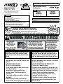 1
1
-
 2
2
-
 3
3
-
 4
4
-
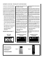 5
5
-
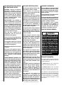 6
6
-
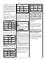 7
7
-
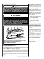 8
8
-
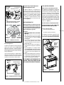 9
9
-
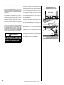 10
10
-
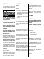 11
11
-
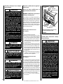 12
12
-
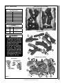 13
13
-
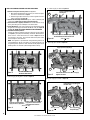 14
14
-
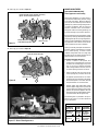 15
15
-
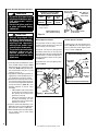 16
16
-
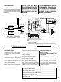 17
17
-
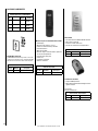 18
18
-
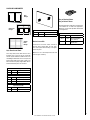 19
19
-
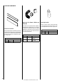 20
20
-
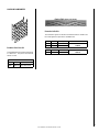 21
21
-
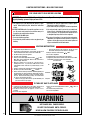 22
22
-
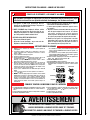 23
23
-
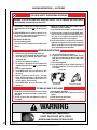 24
24
-
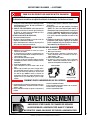 25
25
-
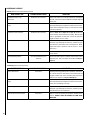 26
26
-
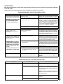 27
27
-
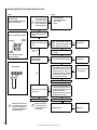 28
28
-
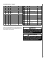 29
29
-
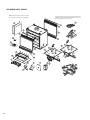 30
30
-
 31
31
-
 32
32


Astria Fireplaces MPBST Manuel utilisateur
- Catégorie
- Cheminées
- Taper
- Manuel utilisateur
dans d''autres langues
- English: Astria Fireplaces MPBST User manual
Documents connexes
Autres documents
-
 Lennox Hearth MLBV-35PM Manuel utilisateur
-
Superior SDV35 Manuel utilisateur
-
Superior Fireplaces BRT40ST Mode d'emploi
-
Lennox merit plus mpb3530cpm-b Manuel utilisateur
-
 Lennox Hearth ADAGIO-EN Manuel utilisateur
-
 Lennox Hearth Products MPB4540CNE Manuel utilisateur
-
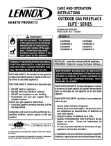 Lennox Hearth Products E42ODGPE-H Manuel utilisateur
-
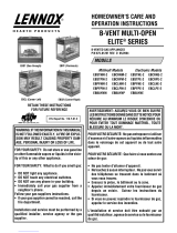 Lennox Hearth EBBAYNM Manuel utilisateur
-
-


